
© Danfoss | FHH | 2018.02 | 1
VIIKH12P
Installation Guide
FHM-CN5
Pre-assembled 3-Way Mixing Shunt
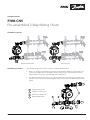
Installation overview
Bottom in bottom out Side in side out
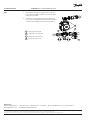
Installation procedure
A
C
B
D
1
The FHM-CN5 must be connected to a system according to the illustrations.
1. Bend 1 is in package. Install bend 1 to the primary side pipe rstly. And then connect bend 1 and
connector 2 together with enclosed O-ring. Finally, connector 2 to 3-way mixing valve must be
tightened with a torque of 30 to 40 Nm with enclosed at gasket.
2. Pre-mounted union nut 3 for connection to the secondary side pipe or directly on a Danfoss man-
ifold. The nut 3 to mixing shunt must be tightened with a torque of 30 to 40 Nm with enclosed at
gasket.
Supply of primary side
Supply of secondary side
Return of secondary side
Return of primary side
B
C
A
D
2
3

2 | © Danfoss | FHH | 2018.02
088U5014 | VIIKH12P
Danfoss A/S
Floor Heating Hydronics • Ulvehavevej 61 • DK-7100 Vejle • Denmark • Phone: +45 7488 8500 • Fax: +45 7488 8501
heating@danfoss.com • www.oorheating.danfoss.com
Danfoss can accept no responsibility for possible errors in catalogues, brochures and other printed material. Danfoss reserves the right to alter its products without notice. This also applies to products already
on order provided that such alterations can be made without subsequential changes being necessary in specications already agreed.
All trademarks in this material are property of the respective companies. Danfoss and the Danfoss logotype are trademarks of Danfoss A/S. All rights reserved.
Installation Guide FHM-CN5 Pre-assembled Mixing Shunt
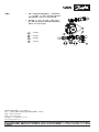
Tips
1. If the primary side pipe is coming from the side, the
bend 1 must be tightened with T-connection 4 with a
torque of 30 to 40 Nm.
2. Connection 5 are tightened from the factory. If leaks
occur due to loosening during transportation, moving
or similar, please tighten at a torque of 30 to 40Nm.
Supply of primary side
Supply of secondary side
Return of secondary side
Return of primary side
B
C
A
D
A
C
B
D
1
4
5
5

© Danfoss | FHH | 2018.02 | 3
VIIKH12P
A
C
B
D
1
2
3
安装指南
FHM-CN5
整体式三通混水中心
I安装概览
底进底出 侧进侧出
安装步骤
必须按图示要求将 FHM-CN5 连接至系统。
1. 活接弯头(1)在包装内。先将图中所示活接弯头(1)装到一次侧供水管上。再将活接弯头
(1)与活接(2)进行连接,密封材料为活接弯头自带的密封圈,并用30~40 Nm的力矩拧
紧。然后再将活接(2)与三通混水阀进行连接,密封材料为产品附带的密封平垫片,并用
30~40 Nm的力矩拧紧螺母。
2. 将图中所示活接(3)先装到二次侧供回水管上或丹佛斯分集水器上。 再将活接(3)与混水中
心连接,密封材料为产品附带的密封平垫片,并用 30-40 Nm 的力矩拧紧螺母。
一次侧供水
二次侧供水
二次侧回水
一次侧回水
B
C
A
D

4 | © Danfoss | FHH | 2018.02
088U5014 | VIIKH12P
丹佛斯自动控制管理(上海)有限公司
地址:上海市宜山路900号科技大楼C楼22层邮编:200233
电话:+86 21 61513000
传真:+86 21 61513100
电子邮件: [email protected]
http://heating.danfoss.cn
小贴士
1. 如果一次侧供回水管是侧进侧出,可将活接弯头
(1)与T型接头(4)连接,密封材料为活接弯头
自带的密封圈,并用30~40Nm的力矩拧紧。
2. 连接螺母(5)在出厂时已拧紧。如果由于在运
输、搬运或类似过程中出现松动而导致泄漏的话,
请用30~40Nm的力矩拧紧。
一次侧供水
二次侧供水
二次侧回水
一次侧回水
B
C
A
D
A
C
B
D
1
4
5
5
-
 1
1
-
 2
2
-
 3
3
-
 4
4


他の言語で
- English: Danfoss FHM-CN5 Installation guide
関連論文
-
Danfoss FHM-CN5 インストールガイド
-
Danfoss FHM-CN1 Pre-assembled Mixing Shunt インストールガイド
-
-
Danfoss FHM-CN2 インストールガイド
-
DEVI 83000300 ユーザーガイド
-
Danfoss 83000300 ユーザーガイド
-
-
-
-