
– 1 –
Quick Start Guide
E092019-CS-R01
150200002102A
www.edge-core.com
54-Port 10G/100G Ethernet Switch
AS5835-54X
1.
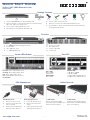
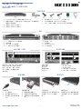
54-Port 10G/100G Ethernet Switch
AS5835-54X
2. Rack mounting kit—2 front-post brackets, 2 rear-post brackets,
20 screws, and 2 ear-locking screws
3. Power cord (included with AC PSUs only)
4. Grounding wire (included with DC PSUs only)
5. Console cable—RJ-45 to D-Sub
6. DC power connector (included with 48 VDC PSU only)
7. Documentation—Quick Start Guide (this document) and Safety
and Regulatory Information
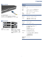
1. 2 x 1000BASE-T RJ-45 management ports
2. Product label
3. 48 x 10G SFP+ ports
4.
6 x 100G QSFP28 ports
5. Console port, USB
6. Grounding screw
7. 2 x AC or DC PSUs
8. 5 x fan trays
3 4 7 8
2
6
1 5
2. B2F Airflow
Install back-to-front (B2F) airflow
fan trays (blue handles) and PSUs
(blue release latches).
Fan Tray Replacement
1. Loosen the fan tray screw.
2. Remove fan tray from the
chassis.
3. Install replacement fan with
matching airflow direction.
PSU Replacement
1. Remove the power cord.
2. Press the release latch and
remove the PSU.
3. Install replacement PSU with
matching airflow direction.
1. F2B Airflow
Remove front-to-back (F2B)
airflow fan trays (red handles) and
PSUs (red release latches).
Package Contents
Overview
FRU Replacement Airflow Reversal
PS1/PS2: Green (OK), Amber (fault)
OS Diag: Green (OK), Amber (fault)
Fan: Green (OK), Amber (fault)
Loc: Flashing Amber (switch locator)
Reset Button
QSFP28 LEDs
1 LED Green (100G)
1 LED Blue (40G)
1-4 LEDs Amber (25G breakout)
1-4 LEDs Purple (10G breakout)
SFP+ LEDs
Green (10G)
Amber (1G)
MGMT LEDs
Green (1G)
System LEDs/Buttons Port LEDs
1 2 3 4 5 6 7

Quick Start Guide
– 2 –
Mount the Switch
Ground the Switch
Connect Power
Warning:
For a safe and reliable installation, use only
the accessories and screws provided with the AS5835-
54X. Use of other accessories and screws could result in
damage to the unit. Any damages incurred by using
unapproved accessories are not covered by the warranty.
Avertissement:
Pour une installation sûre et fiable,
utilisez uniquement les accessoires et les vis fournies avec
le AS5835-54X. L’utilisation d’autres accessoires et vis
pourrait endommager l’appareil. Les dommages causés
par l’utilisation d’accessoires non approuvés ne sont pas
couverts par la garantie.
Caution:
The switch includes plug-in power supply (PSU) and
fan tray modules that are installed into its chassis. Make sure all
installed modules have a matching airflow direction (front-to-
back or back-to-front).
Attention:
Le commutateur comprend des modules
d’alimentation et de modules de ventilation installés dans son
châssis. Assurez-vous que tous les modules installés ont une
direction d’air adaptée (avant-arrière ou arrière-arrière).
Note:
The switch has the Open Network Install Environment
(ONIE) software installer preloaded on the switch, but no switch
software image. Information about compatible switch software
can be found at
www.edge-core.com.
Note:
The switch drawings in this document are for illustration
only and may not match your particular switch model.
Caution:
Installing the switch in a rack requires two people.
One person should position the switch in the rack, while the
other person secures it using the rack screws.
Attention:
L’installation du commutateur dans un rack
nécessite deux personnes. Une personne doit positionner le
commutateur dans le rack, pendant que l’autre assure à l’aide
des vis de rack.
1
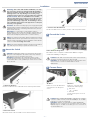
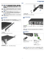
1. Attach the Brackets
Use the included screws to attach the front- and rear-post brackets.
2. Mount the Switch
Mount the switch in the rack and secure it with rack screws.
Caution:
The earth connection must not be removed unless
all supply connections have been disconnected.
Attention:
Le raccordement à la terre ne doit pas être retiré
sauf si toutes les connexions d’alimentation ont été
débranchées.
Caution:
Use a UL/IEC/EN 60950-1 certified power supply to
connect to a DC converter, and a #14 AWG (for 36–75 VDC
PSU) wire to connect to a DC PSU.
Attention:
Utilisez une alimentation certifiée UL/IEC/EN
60950-1 pour le connecter à un convertisseur CC et un câble
AWG #14 (pour -36 VDC à -75 VDC) pour vous connecter à
une alimentation CC.
3. Lock the Rear-Post Brackets
Use the included screws to lock the position of the rear-post brackets.
2
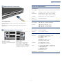
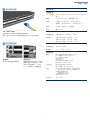
Attach the Grounding Wire
Ground the rack in compliance with ETSI ETS 300 253 using the
included #14 AWG grounding wire.
3
AC Power
Install one or two AC PSUs and
connect them to an AC power
source.
DC Power
Install one or two DC PSUs.
Wire the DC terminal plug:
■
DC return
■
-36 – -75 VDC
■
Ground
Connect a DC power source to
the PSUs.
Installation

Quick Start Guide
– 3 –
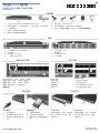
Make Network Connections
Make Management Connections
4
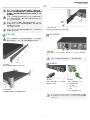
SFP+/QSFP28 Ports
Install transceivers and then connect fiber optic cabling to the
transceiver ports.
Alternatively, connect DAC or AOC cables directly to the SFP+/
QSFP28 slots.
5
Management Ports
Connect Cat. 5e or better twisted-
pair cable.
Console Port
Connect the included console
cable and then configure the
serial connection: 115200 bps, 8
characters, no parity, one stop bit,
8 data bits, and no flow control.
Hardware Specifications
Switch Chassis
Size (WxDxH) 442.5 x 473.3 x 43.95 mm (17.42 x 18.63 x 1.73 in)
Weight 8.815 kg (19.43 lb), with two installed PSUs
Temperature Operating: 0° C to 40° C (32° F to 104° F)
Storage: -40° C to 70° C (-40° F to 158° F)
Humidity Operating: 5% to 95% (non-condensing)
Power
Consumption
356 Watts maximum
AC PSU
Power Rating 100–240 VAC, 50–60 Hz, 400 Watts
AC Input 100-240 VAC, 50-60 Hz, 6–3 A
100–127 VAC, 47–63 Hz, 6.0 A
200–240 VAC, 47–63 Hz, 3.0 A
48 VDC PSU
Power Rating 48 VDC, 400 Watts
DC Input -36 – -75 VDC, 14–7 A
Regulatory Compliances
Emissions EN 55032:2015+AC:2016, Class A
EN 61000-3-2:2014, Class A
EN 61000-3-3:2013
FCC Class A
VCCI Class A
CCC GB 9254-2008, Class A
BSMI Class A, CNS 13438
Immunity EN 55024:2010+A1:2015
IEC 61000-4-2/3/4/5/6/8/11
Safety UL (CSA 22.2 No 60950-1 & UL60950-1)
(CSA 22.2 No 62368-1 & UL62368-1)
CB (IEC/EN60950-1)
(IEC/EN62368-1)
CCC GB4943.1-2011
BSMI, CNS 14336-1
Taiwan RoHS CNS 15663

– 1 –
快速入门指南
E092019-CS-R01
150200002102A
www.edge-core.com
1.
54-
端口
10G/100G
以太网交换机
AS5835-54X
2. 机架安装套件 — 2 个前柱支架, 2 个后柱支架, 20 个螺丝和
2 个吊耳螺丝。
3. 电源线 (仅随交流电源附带)
4. 接地线 (仅随直流电源附带)
5. 控制台线 —RJ-45 转 D-Sub
6. DC 电源转接头 (仅随 48 VDC 电源附带)
7. 文档 —
快速入门指南
(本文档)以及
安全和管制信息
54 端口 10G/100G 以太网交换机
AS5835-54X
1. 2 x 1000BASE-T RJ-45 管理端口
2. 产品标签
3. 48 x 10G SFP+ 端口
4.
6 x 100G QSFP28
端口
5. 控制台端口, USB
6. 接地螺丝
7. 2 x AC 或 DC PSU
8. 5 x 风扇架
347815
2
6
2.B2F 气流
安装从后到前 (B2F)气流风扇
架 (蓝色手柄)和 PSU (蓝色
释放闩锁)。
风扇架更换
1. 松开风扇架螺丝。
2. 从机箱中卸下风扇架。
3. 安装气流方向匹配的更换风
扇。
PSU 更换
1. 拔下电源线。
2. 按下释放闩锁并卸下 PSU。
3. 安装气流方向匹配的更换
PSU。
1.F2B 气流
安装从前到后 (F2B)气流风扇
架 (红色手柄)和 PSU (红色
释放闩锁)。
PS1/PS2: 绿色 (正常),琥珀色 (故障)
诊断 : 绿色 (正常),琥珀色 (故障)
风扇 : 绿色 (正常),琥珀色 (故障)
位置 : 闪烁琥珀色 (开关定位器)
重置按钮
QSFP28 LED
1 LED 绿色 (100G)
1 LED 蓝色 (40G)
1-4 LED 琥珀色 (25G 突破 )
1-4 LED 紫色 (10G 突破 )
SFP+ LED
绿色 (10G)
琥珀色 (1G)
管理 LED
绿色 (1G)
包装清单
1234567
概述
系统 LED/ 按钮 端口 LED
FRU 更换 气流反向

快速入门指南
– 2 –
安装交换机
将交换机接地
连接电源
警告:
为了可以更安全的使用与安装机台,请务必使用
AS5835-54X 随货附赠的配件,避免导致设备损坏或其他
风险产生。使用未经批准的配件造成的任何损坏,均不在
保修范围内。
小心:
本交换机的机箱中安装有插入式电源 (PSU) 和风扇
架模块。确保所有安装的模块气流方向匹配 (从前到后或
从后到前)。
注意:
本交换机上已预装了 Open Network Install
Environment (ONIE) 软件安装程序,但没有交换机软件映
像。在以下网站可以找到有关兼容交换机软件的信息:
www.edge-core.com。
注意:
本文档中的交换机图示仅供参考,可能与您的具体
交换机型号不符。
小心:
将此交换机安装在机架中时需要两个人。一个人应
在机架中托住交换机,另一个人使用机架螺丝固定它。
1
1. 安装支架
使用附带的螺丝安装前柱和后柱支架。
2. 安装交换机
将交换机安装在机架中,并用机架螺丝将其固定。
小心:
必须在所有电源连接都断开的情况下才能移除接地
连接。
小心:
使用 UL/IEC/EN 60950-1 认证电源连接到 DC 转换
器,使用 #14 AWG (对于 36–75 VDC PSU)线连接到 DC
PSU。
3. 锁定后柱支架
使用附带的螺丝锁定后柱支架的位置。
2
连接接地线
使用附带的 #14 AWG 接地线,按照 ETSI ETS 300 253 规范对机架
进行接地。
3
交流电源
安装一个或两个交流 PSU 并将
其连接到交流电源。
直流电源
安装一个或两个直流 PSU。
连线直流端子插头:
■
DC 回返
■
-36 – -75 VDC
■
接地
将直流电源连接到 PSU
安装

快速入门指南
– 3 –
建立网络连接
建立管理连接
4
SFP+/QSFP28 端口
安装收发器,然后将光缆连接到收发器端口。
或者,将 DAC 或 AOC 线缆直接连接到 SFP+/QSFP28 插槽。
5
管理端口
连接 5e 类或更好双绞线缆。
控制台端口
连接附带的控制台线缆,然后配
置串行连接:115200 bps,8 个
字符,无奇偶校验,一个停止
位, 8 个数据位,无流量控制。
硬件规格
交换机机箱
尺寸 (WxDxH) 442.5 x 473.3 x 43.95 mm (17.42 x 18.63 x 1.73
英寸)
重量 8.815 kg (19.43 lb),安装有两个 PSU
温度 工作时:0° C 到 40° C (32° F 到 104° F)
存放时:-40° C 到 70° C (-40° F 到 158° F)
湿度 工作时:5% 到 95% (无冷凝)
功耗 最大 356 W
AC PSU
电源额定值 100–240 VAC, 50-60 Hz, 400 W
交流输入 100-240 V 交流, 50-60 Hz, 6-3 A
100-127 V 交流, 47-63 Hz, 3.0 A
200-240 V 交流, 47–63 Hz, 3.0 A
48 VDC PSU
电源额定值 48 VDC, 400 W
直流输入 -36 – -75 VDC, 14–7 A
管制符合性
辐射
EN 55032:2015+AC:2016, Class A
EN 61000-3-2:2014, Class A
EN 61000-3-3:2013
FCC Class A
VCCI Class A
CCC GB 9254-2008, Class A
BSMI Class A, CNS 13438
抗干扰性
EN 55024:2010+A1:2015
IEC 61000-4-2/3/4/5/6/8/11
安全
UL (CSA 22.2 No 60950-1 & UL60950-1)
(CSA 22.2 No 62368-1 & UL62368-1)
CB (IEC/EN60950-1)
(IEC/EN62368-1)
CCC GB4943.1-2011
BSMI, CNS 14336-1
台湾 RoHS
CNS 15663

– 1 –
快速入門指南
E092019-CS-R01
150200002102A
www.edge-core.com
1.
54
埠
10G/100G
乙太網路交換器
AS5835-54X
2. 機櫃安裝套件 —2 個前柱托架、2 個後柱托架、20 個螺絲和 2
個固定片鎖定螺絲
3. 電源線 (僅 AC PSU 隨附)
4. 接地線 (僅 DC PSU 隨附)
5. 控制電纜 (Console Cable)- RJ45 轉 D-Sub
6. DC 電源轉接頭 (僅 48 VDC PSU 隨附)
7. 文件-
快速入門指南
(本文件)及
安全及法規資訊
54 埠 10G/100G 乙太網路交換器
AS5835-54X
1. 2 x 1000BASE-T RJ-45 管理埠
2. 產品標籤
3. 48 x 10G SFP+ 連接埠
4.
6 x 100G QSFP28
連接埠
5. 控制埠,USB
6. 接地螺絲
7. 2 x AC 或 DC PSUs
8. 5 x 風扇托盤
347815
2
6
2.B2F 氣流
安裝後至前 (B2F) 氣流風扇托盤
(藍色握把)及 PSU (藍色釋放
桿)。
更換風扇托盤
1. 鬆開風扇托盤螺絲。
2. 從機殼內取出風扇托盤。
3. 安裝氣流方向相符的替換風
扇。
更換 PSU
1. 取下電源線。
2. 按住釋放桿並取出 PSU。
3. 安裝氣流方向相符的替換
PSU。
1.F2B 氣流
移除前至後 (F2B) 氣流風扇 (紅
色握把)及 PSU (紅色釋放
桿)。
PS1/PS2: 綠燈 (OK),黃燈 (故障)
Diag: 綠燈 (OK),黃燈 (故障)
Fan: 綠燈 (OK),黃燈 (故障)
Loc: 閃黃燈 (交換器定位器)
重設按鈕
QSFP28 LEDs
1 LED 綠色 (100G)
1 LED 藍色 (40G)
1-4 LEDs 黃色 (25G 突圍)
1-4 LEDs 紫色 (10G 突圍)
SFP+ LEDs
綠色 (10G)
黃色 (1G)
MGMT LEDs
綠色 (1G)
包裝內容物
1234567
簡介
系統 LED /按鈕 連接埠 LED
更換 FRU 氣流反向

快速入門指南
– 2 –
安裝交換器
將交換器接地
連接電源
警告: 為了可以更安全的使用與安裝機台,請務必使用
AS5835-54X 隨貨附贈的配件,避免導致設備損壞或其他
風險產生。 使用未經批准的配件造成的任何損壞,均不在
保修範圍內。
注意:
交換器包含有安裝在底座上之插入式電源供應器 (
PSU)及風扇托盤模組。確認所有已安裝模組的氣流方向一
致 (前至後或後至前)。
說明:
交換器上有預載入的開放網路安裝環境 (ONIE)
軟體安裝程式,但沒有交換器軟體映像檔。關於相容交換
器軟體的資訊可參閱:
www.edge-core.com。
說明:
本文件中的交換器示意圖僅供參考,可能與特定交
換器型號有所差異。
注意:
需要兩個人,將交換器裝到機櫃上。一個人應將交
換器放到機櫃中,而另一個人使用機櫃螺絲將其固定。
1
1. 安裝托架
使用內附的螺絲安裝前柱及後柱托架。
2. 安裝交換器
將交換器裝到機櫃中並用機櫃螺絲固定。
注意:
在切斷所有電源接線前,不得移除接地連接。
注意:
使用 UL/IEC/EN 60950-1 認證電源連接至 DC 轉換
器,並使用 #14 AWG (用於 36–75 VDC PSU)接地線連接
至 DC PSU。
3. 鎖住後柱托架
使用內附的螺絲固定後柱托架的位置。
2
安裝接地線
使用內附的 #14 AWG 接地線,按照 ETSI ETS 300 253 將機櫃接
地。
3
AC 電源
安裝一個或兩個 AC PSU 並將其
連接至 AC 電源。
DC 電源
安裝一個或兩個 DC PSU。
DC 終端插頭接線:
■
DC 回路
■
-36 – -75 VDC
■
接地
將 DC 電源連接至 PSU。
安裝

快速入門指南
– 3 –
進行網路連線
進行管理連接
4
SFP+/QSFP28 連接埠
安裝收發器,然後將光纖電纜連接至收發器連接埠。
或可將 DAC 或 AOC 電纜直接連接至 SFP+/QSFP28 插槽。
5
管理埠
連接 5e 類或以上的雙絞線。
控制埠
連接隨附的控制線,接著配置串
列連接:115200 bps、8 個字
元、無奇偶 (檢驗碼)、1 個停
止位元、8 個資料位元,並且無
流量控制。
硬體規格
交換器機箱
尺寸(寬 x 深
x 高)
442.5 x 473.3 x 43.95 mm (17.42 x 18.63 x 1.73
吋)
重量 8.815 kg (19.43 lb),包含兩個安裝 PSU
溫度 操作:0° C 至 40° C (32° F 至 104° F)
儲存:-40° C 至 70° C (-40° F 至 158° F)
濕度 操作:5% 至 95% (無冷凝)
耗電量 最大 356 瓦
AC PSU
額定功率 100-240 VAC、50-60 Hz、400 瓦
AC 輸入 100-240 VAC、50-60 Hz、6-3 A
100-127 VAC、47-63 Hz、6.0 A
200-240 VAC、47-63 Hz、3.0 A
48 VDC PSU
額定功率 48 VDC、400 瓦
DC 輸入 -36 – -75 VDC、14–7 A
符合法規
排放
EN 55032:2015+AC:2016, Class A
EN 61000-3-2:2014, Class A
EN 61000-3-3:2013
FCC Class A
VCCI Class A
CCC GB 9254-2008, Class A
BSMI Class A, CNS 13438
電磁耐受性
EN 55024:2010+A1:2015
IEC 61000-4-2/3/4/5/6/8/11
安全性
UL (CSA 22.2 No 60950-1 & UL60950-1)
(CSA 22.2 No 62368-1 & UL62368-1)
CB (IEC/EN60950-1)
(IEC/EN62368-1)
CCC GB4943.1-2011
BSMI, CNS 14336-1
臺灣限用有害
物質指令
(RoHS)
CNS 15663
-
 1
1
-
 2
2
-
 3
3
-
 4
4
-
 5
5
-
 6
6
-
 7
7
-
 8
8
-
 9
9


他の言語で
- English: Edge-Core AS5835-54X User manual