Delta Electronics DeviceNet Slave Communication Module DVPDT02-H2 ユーザーマニュアル
- タイプ
- ユーザーマニュアル

Warning
Please read this instruction sheet carefully before use and follow this instruction to operate the device in order to
prevent damages on the device or injuries to staff.
Switch off the power before wiring.
This instruction sheet only provides introductory information on electrical specification, functions, wiring,
trouble-shooting and peripherals for DVPDT02-H2. Details of DeviceNet protocol are not included in this sheet. For
more information on DeviceNet protocol, please refer to relevant reference or literatures.
DVPDT02-H2 is an OPEN-TYPE device and therefore should be installed in an enclosure free of airborne dust,
humidity, electric shock and vibration. The enclosure should prevent non-maintenance staff from operating the device
(e.g. key or specific tools are required to open the enclosure) in case danger and damage on the device may occur.
DVPDT02-H2 is to be used for controlling the operating machine and equipment. In order not to damage it, only
qualified professional staff familiar with the structure and operation of it can install, operate, wire and maintain it.
DO NOT connect input AC power supply to any of the I/O terminals; otherwise serious damage may occur. Check all
the wiring again before switching on the power, and DO NOT touch any terminal when the power is switched on.
Make sure the ground terminal is correctly grounded in order to prevent electromagnetic interference.
Introduction
Thank you for choosing Delta DVPDT02-H2 DeviceNet communication module. DVPDT02-H2 can be applied
to the connection with DVP-EH2 series PLC MPU in a DeviceNet network.
Features
1. Supports Group 2 only servers.
2. Supports explicit connection in the pre-defined
master/slave connection group.
3. The length of I/O data can be freely configured
through DeviceNet network configuration tool.
4. Supports polling.
5. Supports EDS files in DeviceNet network
configuration tools.
6. I/O data is extendable to 200 bytes.
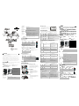
Product Profile & Outline
POWER
NS
MS
DR 1
DR 0
IN 0
IN 1
X
10
X
10
2
3
5
4
6
7
8
9
1
40 [1.575 ]
7
[
0
.
2
7
6
]
9
0
[
3
.
5
4
3
]
82 [3.228 ]
Unit: mm/[inch]
1
Extension port
2
Node address setup rotary switch
3
Function setup DIP switch
4
POWER indicator
5
MS (Module Status) indicator
6
NS (Network Status) indicator
7
DeviceNet connector
8
DIN rail
9
DIN rail clip
Specifications
DeviceNet Connector
Type Removable connector (5.08mm)
Transmission method CAN
Transmission cable 2 communication cables, 2 power cables, 1 shielded cable
Electrical isolation 500V DC
ENGLISH
Communication
Message type I/O polling; explicit
Series transmission
speed
125kbps; 250kbps; 500kbps (bits per second)
Equipment type 12
Company ID 799 (Delta Electronics, Inc.)
Electrical Specifications
Voltage:11 ~ 25V DC (supplied by the power cable in the network)
DeviceNet
Current: 28mA (typical), 125mA impulse current (24V DC)
Environment
Standards IEC 61131-2, UL508
Storage/operation
Storage: -25ºC ~ 70ºC (temperature), 5 ~ 95% (humidity)
Operation: 0ºC ~ 55 ºC (temperature), 50 ~ 95% (humidity), pollution degree 2
Shock/vibration
immunity
International standards: IEC 61131-2, IEC 68-2-6 (TEST Fc)/IEC 61131-2 & IEC
68-2-27 (TEST Ea)
Interference immunity
ESD (IEC 61131-2, IEC 61000-4-2): 8KV Air Discharge
EFT (IEC 61131-2, IEC 61000-4-4): Power Line: 2KV, Digital I/O: 1KV
Analog & Communication I/O: 1KV
Damped-Oscillatory Wave: Power Line: 1KV, Digital I/O: 1KV
RS (IEC 61131-2, IEC 61000-4-3): 26MHz ~ 1GHz, 10V/m
Certificates CE, UL
Components
DeviceNet Connector
To connect to DeviceNet network, use the connector enclosed with DVPDT02-H2 or any connectors you can
buy in the store for wiring.
PIN Signal Color Description
1 V- Black 0V DC
2 CAN_L Blue Signal-
3 SHIELD - Shielded cable
4 CAN_H White Signal+
5 V+ Red 24V DC
1
2
3
4
5
Node Address Setup Rotary Switch
The two rotary MAC ID setup switches set up the node addresses on DeviceNet
network in decimal form. Setup range: 00 ~ 63 (64 ~ 99 are forbidden)
Rotary switch x 10
1
x 10
0
Multiple × 10 × 1
X
1 0
X
1 0
Example: If you need to set the node address of DVPDT02-H2 as 26, simply switch the corresponding rotary
switch of x10
1
to “2” and the corresponding rotary switch of x10
0
to “6”.
Switch setting Description
0…63 Valid DeviceNet MAC ID
64…99 Invalid DeviceNet MAC ID
Note: The changed values on switches are only valid
when DVPDT02-H2 is re-powered. When
DVPDT02-H2 is operating, changing the set value of
MAC ID will be invalid.
Function Setup DIP Switch
The function setup switches are for:
1. Setting up I/O data holding function (IN0)
2. Setting up the baud rates of DeviceNet network (DR0 ~ DR1)
DR1 DR0 Baud rate
OFF OFF 125kbps
OFF ON 250kbps
ON OFF 500kbps
ON ON Incorrect setting
OFF
When the DeviceNet connection is interrupted, the content in
the buffer area will not be held.
IN0
ON
When the DeviceNet connection is interrupted, the content in
the buffer area will be held.
IN1 Reserved
DR 1
DR 0
IN 0
IN 1
Extension Port
The extension port on DVPDT02-H2 is used for the connection to the next DVPDT02-H2 or extension m odules
of DVP-EH2 series PLC MPU.
Basic Operation
Connecting DVPDT02-H2 to DVP-EH2 Series PLC MPU
STOP
RUN
0 1
IN
OUT
POW ER
RUN
ERR O R
BAT. LO W
DV P -20 EH
Switch off DVP-EH2. Open the connection port on the
right hand side of DVP-EH2 and connect DVPDT02-H2 to
DVP-EH2. Switch on DVP-EH2, and DVP-EH2 will supply
power to DVPDT02-H2. There is no need to connect
DVPDT02-H2 to an external power supply.
Install DVP-EH2 and DVPDT02-H2 on DIN Rail
STOP RUN
0 1
IN
OUT
POWE R
RUN
ERRO R
BAT.LO W
DV P- 20E H
1. Use 35mm DIN rail.
2. Open the DIN rail clips on DVP-EH2 and
DVPDT02-H2. Insert DVP-EH2 and DVPDT02-H2
onto the DIN rail.
3. Clip up the DIN rail clips on DVP-EH2 and
DVPDT02-H2 to fix DVP-EH2 and DVPDT02-H2 on
the DIN rail.
As shown in the figure.
Connecting to DeviceNet Connector
1. The colors of the PINs on the DeviceNet connector
match the colors of the connection cables. Make sure
you connect the cable to the right PIN.
2. We recommend you also apply Delta’s power module
in the connection.
As shown in the figure.
Installation & Wiring
1. Install DVPDT02-H2 in an enclosure with sufficient space
around it to allow heat dissipation (see the figure).
2. DO NOT place the I/O signal wires and power supply wire
in the same wiring circuit.
D> 5 0 mm
DT 02-H 2
DD
D
D
EH 2 PL C
D
D
Control Register
The control registers (CR) are the registers inside DVPDT02-H2. See the table below for the definitions of all
the CRs. DVP-EH2 series PLC MPU can read or write the CR allowed through DFROM/DTO instructions.
CR# Attribute
Content High byte Low byte
#0 Read Model name DVPDT02-H2 model code = H’0230
#1 Read Firmware version
Displaying the current firmware version in hex, e.g. V1.12 is
indicated as H’0112.
#2 Read Length of I/O data Length of output I/O data Length of input I/O data
#3 ~ #102 Read/write
Input data mapping Area for storing data from DVPDT02-H2 to DeviceNet master
#103 ~ #202
Read/write
Output data mapping Area for storing data from DeviceNet master to DVPD T02-H2
#203 ~ #215 Set up by the system. DO NOT use it.
#216 ~ #250 Reserved
#251 Read Error
Register for storing errors. See
for error codes.
#252 ~ #254 Reserved
#255 Read MPU status
CR#255 = K0: MPU in STOP status
CR#255 = K1: MPU in RUN status
LED Indicators & Trouble-Shooting
There are 3 LED indicators on DVPDT02-H2. POWER indicator displays the status of working power. NS
indicator and MS indicator display the connection status of the comm unication.
NS LED
LED status Indication How to deal with it?
Off
No power, or DVPDT02-H2 has not completed
the Dup_MAC_ID test yet.
1. Check the power of DVPDT02-H2 and see if the
connection is normal.
2. Check if the node communication on the network
is
normal.
3. Make sure at least one or more nodes on the
network are operational at the same time and the
baud rate is the same as that of DVPDT02-H2.
4. Check if the baud rate of DVPDT02-
H2 is the same
as that of other nodes.
Green light
flashes
DVPDT02-H2 is on-line and has passed
Dup_MAC_ID test but has not established
connections to other nodes.
1. Correctly configure the slave module.
2. Re-
download the configured data to the master and
set the master PLC to be in RUN status.
Green light on
DVPDT02-H2 is on-line and is normally
connected to the master.
--
Red light
flashes
DVPDT02-H2 is on-line, but I/O connections
are timed-out.
1. Check if the network connection is normal.
2. Check if the master operates normally.
Red light on
The communication is down; MAC ID is
repeated; no network power; bus-off
1. Make sure all the MAC IDs on the network are not
repeated.
2. Check if the network installation is normal.
3. Check if the baud rate of DVPDT02-
H2 is consistent
LED status Indication How to deal with it?
with that of the network.
4. Check if the node address of DVPDT02-H2 is a
valid one.
5. Check if the network power is normal.
MS LED
LED status Indication How to deal with it?
Off No power
Check the power of DVPDT02-H2 and see if the
connection is normal.
Green light
flashes
Waiting for I/O data; no I/O data; the program
of DVPDT02-H2 is being edited.
Switch DVPDT02-H2 to RUN status to start I/O data
exchange.
Green light on
I/O data are normal --
Red light
flashes
Recoverable fault Re-power DVPDT02-H2
Red light on Hardware error
1. Find out the cause of error in CR#251.
2. Send back to the factory for repair if necessary.
NS LED + MS LED
LED status
NS LED
MS LED
Indication How to deal with it?
Off Off No power
Check the power of DVPDT02-H2 and see if the
connection is normal.
Off
Green light
on
DVPDT02-H2 has not completed the
Dup_MAC_ID test yet.
Make sure at least one or more node
on the network is
operational at the same time and baud rate as the
DVPDT02-H2 module.
Red light
on
Red light
flashes
No network power
1. Check if the network cable is correctly connected to
DVPDT02-H2.
2. Check if the network power works normally.
Red light
on
Green light
on
Dup_MAC_ID test has failed; bus-off
1. Make sure DVPDT02-H2 has a unique address.
2. Re-power DVPDT02-H2.
Red light
on
Red light on
Hardware error Send your DVPDT02-H2 back to the factory for repair.
Error Codes
Code
Description How to deal with it?
00 DVPDT02-H2 operates normally. --
E2 I/O off-line
1. Check if the network connection is normal.
2. Check if the master operates normally.
F0 Dup_MAC_ID test has failed.
1. Make sure DVPDT02-H2 has a unique address.
2. Re-power DVPDT02-H2.
F2 Working power in low voltage
Check if the power of DVPDT02-H2 and MPU is
normal.
F3 Entering test mode Re-power DVPDT02-H2
F4 BUS-OFF Re-power DVPDT02-H2
F5 No network power detected
1. Check if the network cable works normally.
2. Check if the network power works normally.
F7 Internal error. GPIO detection error. Send your DVPDT02-H2 back to the factory for repair.
F8 Internal error. Manufacturing error. Send your DVPDT02-H2 back to the factory for repair.
F9 Internal error. Configured memory polling error. Send your DVPDT02-H2 back to the factory for repair.
DVPDT02-H2 DeviceNet
DeviceNet
DVPDT02-H2 DVPDT02-H2 DeviceNet DeviceNet
DVP-EH2 PLC
1. Group 2 only servers
2.
3. I/O DeviceNet
4.
5. DeviceNet EDS
6. I/O 200 bytes
POWER
NS
MS
DR 1
DR 0
IN 0
IN 1
X
10
X
10
2
3
5
4
6
7
8
9
1
40 [1.5 75]
7
[
0
.
2
7
6
]
9
0
[
3
.
5
4
3
]
82 [3.2 28]
mm/[inch]
1
2
3
4
POWER
5
MS (Module Status)
6
NS (Network Status)
7
DeviceNet
8
DIN
9
DIN
DeviceNet
5.08mm
CAN
2 2 1
500V DC
I/O
125kbps; 250kbps; 500kbps
12
ID 799
11 ~ 25V DC
DeviceNet
28mA 125mA 24V DC
IEC 61131-2 UL508
-25ºC ~ 70ºC 5 ~ 95%
0ºC ~ 55 ºC 50 ~ 95% 2
IEC 61131-2 IEC 68-2-6 (TEST Fc)/IEC 61131-2 & IEC 68-2-27 (TEST Ea)
ESD (IEC 61131-2, IEC 61000-4-2): 8KV Air Discharge
EFT (IEC 61131-2, IEC 61000-4-4): Power Line: 2KV, Digital I/O: 1KV
Analog & Communication I/O: 1KV
Damped-Oscillatory Wave: Power Line: 1KV, Digital I/O: 1KV
RS (IEC 61131-2, IEC 61000-4-3): 26MHz ~ 1GHz, 10V/m
CE UL
DeviceNet
DeviceNet DVPDT02-H2
1 V- 0V DC
2 CAN_L Signal-
3 SHIELD -
4 CAN_H Signal+
5 V+ 24V DC
1
2
3
4
5
DeviceNet
00 ~ 63 64 ~ 99
x 10
1
x 10
0
× 10 × 1
X
1 0
X
1 0
DVPDT02-H2 26 x10
1
2 x10
0
6
0 ~ 63
DeviceNet
64 ~ 99
DeviceNet
DVPDT02-H2
DVPDT02-H2

(DIP)
1. IN0
2. DeviceNet DR0 ~ DR1
DR1 DR0
OFF OFF 125kbps
OFF ON 250kbps
ON OFF 500kbps
ON ON
OFF
DeviceNet
IN0
ON
DeviceNet
IN1
DR 1
DR 0
IN 0
IN 1
DVPDT02-H2 DVPDT02-H2 DVP-EH2
DVP-EH2 PLC DVPDT02-H2
STOP
RUN
0 1
IN
OU T
PO W E R
RU N
ER R O R
BAT . L O W
DVP -20E H
DVP-EH2 PLC DVP-EH2 PLC
DVPDT02-H2
DVP-EH2
DVP-EH2 DVP-EH2 DVPDT02-H2
DVP-EH2 DVPDT02-H2
DVPDT02-H2
DVP-EH2 PLC DVPDT02-H2
STOP
RUN
0 1
IN
OUT
POWE R
RUN
ERRO R
BAT. LO W
DV P -20 EH
1. 35mm DIN
2. DVP-EH2 PLC DVPDT02-H2
DIN DVP-EH2 PLC
DVPDT02-H2 DIN
3. DVP-EH2 PLC DVPDT02-H2
DIN DVP-EH2 PLC
DVPDT02-H2 DIN
DeviceNet
1.
2.
1. DVPDT02-H2
DVPDT02-H2
2.
D> 50mm
DT 02 -H2
DD
D
D
EH 2
D
D
CR (Control Register) DVPDT02-H2 CR DVP-EH2 DFROM/DTO
CR
CR
#0
DVPDT02-H2 = H’0230
#1
16 H’0112 V1.12
#2
I/O I/O I/O
#3 ~ #102
DVPDT02-H2 DeviceNet
#103 ~ #202
DeviceNet DVPDT02-H2
#203 ~ #215
#216 ~ #250
#251
#252 ~ #254
#255
CR#255 = K0 PLC STOP
CR#255 = K1 PLC RUN
LED
DVPDT02-H2 LED POWER LED DVPDT02-H2 NS LED MS LED
DVPDT02-H2
NS LED
LED
ID
1. DVPDT02-H2
2.
3.
4. DVPDT02-H2
ID
1.
2. PLC
RUN
I/O
1.
2.
1.
LED
BUS-OFF 2.
3. DVPDT02-H2
4. DVPDT02-H2
5.
MS LED
LED
DVPDT02-H2
I/O I/O
PLC
PLC RUN IO
I/O
DVPDT02-H2
1. CR#251
2.
NS LED MS LED
LED
NS LED MS LED
DVPDT02-H2
MAC ID
DVPDT02-H2
1.
2.
BUS-OFF
1. DVPDT02-H2
2. DVPDT02-H2
00
E2
I/O 1. 2.
F0
1. DVPDT02-H2
2. DVPDT02-H2
F2
DVPDT02-H2 PLC
F3
DVPDT02-H2
F4 BUS-OFF
DVPDT02-H2
F5
1. 2.
F7
GPIO
F8
F9
DVPDT02-H2 DeviceNet DeviceNet
( )
DVPDT02-H2 DVPDT02-H2 DeviceNet DeviceNet
DVP-EH2 PLC
1. Group 2 only servers
2.
3. I/O DeviceNet
4.
5. DeviceNet EDS
6. I/O 200 bytes
POWER
NS
MS
DR 1
DR 0
IN 0
IN 1
X
10
X
10
2
3
5
4
6
7
8
9
1
40 [1.5 75]
7
[
0
.
2
7
6
]
9
0
[
3
.
5
4
3
]
82 [3.2 28]
mm/[inch]
1
2
3
4
POWER
5
MS Module Status
6
NS Network Status
7
DeviceNet
8
DIN
9
DIN
DeviceNet
5.08mm
CAN
2 2 1
500V DC
I/O
125k bps; 250kbps; 500kbps
12
ID 799
11 ~ 25V DC
DeviceNet
28mA 125mA 24V DC
IEC 61131-2 UL508
-25ºC ~ 70ºC 5 ~ 95%
0ºC ~ 55 ºC 50 ~ 95% 2
IEC 61131-2 IEC 68-2-6 (TEST Fc)/IEC 61131-2 & IEC 68-2-27 (TEST Ea)
ESD IEC 61131-2, IEC 61000-4-2 : 8KV Air Discharge
EFT IEC 61131-2, IEC 61000-4-4 : Power Line: 2KV, Digital I/O: 1KV
Analog & Communication I/O: 1KV
Damped-Oscillatory Wave: Power Line: 1KV, Digital I/O: 1KV
RS (IEC 61131-2, IEC 61000-4-3): 26MHz ~ 1GHz, 10V/m
CE UL
DeviceNet
DeviceNet DVPDT02-H2
1 V- 0V DC
2 CAN_L Signal-
3 SHIELD -
4 CAN_H Signal+
5 V+
24V DC
1
2
3
4
5
DeviceNet
00 ~ 63 64 ~ 99
x 10
1
x 10
0
× 10 × 1
X
1 0
X
1 0
DVPDT02-H2 26 x10
1
2 x10
0
6
0 ~ 63
DeviceNet
64 ~ 99 DeviceNet
DVPDT02-H2
DVPDT02-H2
(DIP)
1. IN0
2. DeviceNet DR0 ~ DR1
DR1 DR0
OFF OFF 125kbps
OFF ON 250kbps
ON OFF 500kbps
ON ON
OFF
DeviceNet
IN0
ON DeviceNet
IN1
DR 1
DR 0
IN 0
IN 1
DVPDT02-H2 DVPDT02-H2 DVP-EH2
DVP-EH2 PLC DVPDT02-H2
STOP
RUN
0 1
IN
OU T
PO W E R
RU N
ER R O R
BA T. LO W
DVP-2 0EH
DVP-EH2 PLC DVP-EH2 PLC
DVPDT02-H2
DVP-EH2
DVP-EH2 DVP-EH2 DVPDT02-H2
DVP-EH2 DVPDT02-H2
DVPDT02-H2
DVP-EH2 PLC DVPDT02-H2
STOP RUN
0 1
IN
OUT
POW ER
RUN
ERR O R
BAT. LO W
DV P -20 E H
1. 35mm DIN
2. DVP-EH2 PLC DVPDT02-H2
DIN DVP-EH2 PLC
DVPDT02-H2 DIN
3. DVP-EH2 PLC DVPDT02-H2
DIN DVP-EH2 PLC
DVPDT02-H2 DIN
DeviceNet
1.
2.
1. DVPDT02-H2
DVPDT02-H2
2.
D> 50m m
DT 02- H2
DD
D
D
EH 2
D
D
CR (Control Register) DVPDT02-H2 CR DVP-EH2 DFROM/DTO
CR
CR
#0 DVPDT02-H2 = H’0230
#1
16 H’0112 V1.12
#2 I/O I/O I/O
#3 ~ #102
DVPDT02-H2 DeviceNet
#103 ~ #202 DeviceNet DVPDT02-H2
#203 ~ #215
#216 ~ #250
#251
#252 ~ #254
#255
CR#255 = K0 PLC STOP
CR#255 = K1 PLC RUN
LED
DVPDT02-H2 LED POWER LED DVPDT02-H2 NS LED MS LED
DVPDT02-H2
NS LED
LED
ID
1. DVPDT02-H2
2.
3.
4. DVPDT02-H2
ID
1.
2. PLC
RUN
I/O
1.
2.
(BUS-OFF)
1.
2.
LED
3. DVPDT02-H2
4. DVPDT02-H2
5.
MS LED
LED
DVPDT02-H2
I/O I/O
PLC
PLC RUN I/O
I/O
DVPDT02-H2
1. CR#251
2.
NS LED MS LED
LED
NS LED MS LED
DVPDT02-H2
MAC ID
DVPDT02-H2
1.
2.
00
E2
I/O
1.
2.
F0
1. DVPDT02-H2
2. DVPDT02-H2
F2 DVPDT02-H2 PLC
F3 DVPDT02-H2
F4 BUS-OFF
DVPDT02-H2
F5
1.
2.
F7 GPIO
F8
F9
-
 1
1
-
 2
2


