Delta Electronics Distribution Box TAP-CN01/02/03 ユーザーマニュアル
- タイプ
- ユーザーマニュアル

Warning
Please read this instruction sheet ca refully before use and follow the sheet to operate TAP-CN01//02/03 in order to
prevent dama ges on the device or injuries to staff.
Switch off the power before wiring.
This instruction only provides introductory information on electrical specifications, functions, wiring,
trouble-shooting and peripherals for TAP-CN01/0 2/03.
TAP-CN01/02/03 is an OPEN-TYPE device and th erefore should be installed in an enclosure free of airborne dust,
humidity, electric sho ck and vibration. The enclosure should prevent non-maintenance staff from operating the
device (e.g. key or specific tools are required to open the enclosure) in case danger and damage on the device may
occur.
In order not to damage it, only qualified professional staff familiar with the structure a nd operation of
TAP-CN01/02/03 can install, operate, wire and repair it.
DO NOT connect input AC power supply to any of the I/O terminals; otherwise serious damage may occur. Check all
the wiring again before switching o n the power and DO NOT touch any terminal when the power is switched on.
Introduction
Thank you very much for choosing Delta TAP-CN01/02/03 distribution box. TAP-CN01/02/03 is the distribution
box for the connection of main cable and sub cable in DeviceNet or CANopen. TB1 and T B2 are for connecting
main cables, and TB3 ~ TB5 are for connecting sub cables. TAP-CN01/02/03 formulates a termination
resistance, which is switched by the setup switch.
Nameplate Explanation
VX.XXXX
MADE IN XXXXXX
RT U DE NT 00 T7 20 00 01
MADE IN XXXXXX
CN010 000W7 250001
Model name
Barcod e, Seria l No.
Version
Serial No. Explanation
CN0 X0 00
W
00 01
0
7
25
Pr odu ction No .
Pr odu ction week
Pr odu ction ye ar (20 07 )
Pr odu ction pla nt (W: W uj ia ng T: Taoyua n)
Ver si on No .
Mo del na me
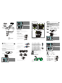
Product Profile & Outline
1
DeviceNet/CANopen main cable connector
2
DeviceNet/CANopen main cable connector
3
DeviceNet/CANopen sub cable connector
4
Termination resistance setup switch
5
121Ω termination resistance
1
2
3
4
5
6
66 .50[2 .62 ]
87. 00[3 .43 ]
Unit: mm
6
DIN rail
ENGLISH
1
DeviceNet/CANopen main cable connector
2
DeviceNet/CANopen main cable connector
3
DeviceNet/CANopen sub cable connector
4
DeviceNet/CANopen sub cable connector
5
DeviceNet/CANopen sub cable connector
6
Termination resistance setup switch
7
121Ω termination resistance
1
2
3
4
5
6
7
8
96.50[ 3.80]
97.00 [3.43]
Unit: mm
8
DIN rail
1
DeviceNet/CANopen main cable connector
2
DeviceNet/CANopen main cable connector
3
DeviceNet/CANopen sub cable connector
4
DeviceNet/CANopen sub cable connector
5
DeviceNet/CANopen sub cable connector
6
Termination resistance setup switch
7
121Ω termination resistance
5
6
7
8
1
2
3
4
66. 50[ 2.62 ]
66. 50[2. 62]
Unit: mm
8
DIN rail
Specifications
Electrical Specifications
DeviceNet Voltage: 11 ~ 25V DC (supplied by the power cable in the network)
Environment
Operation/Storage
Operation: 0ºC ~ 55ºC (temperature), 50 ~ 95% (humidity), pollution degree 2
Storage: -25ºC ~ 70ºC (temperature), 5 ~ 95% (humidity)
How to Install
Use efficient tool to peel the communication cable
for approx. 30mm. DO NOT damage the shielded
cable while peeling.
Ap pro x. 30m m
Peel off the metallic shielded net and foil and you
will see 2 power cables (in red and black), 2 signal
cables (in blue and white) and 1 shielded cable.
Sh ield ed c able
Peel off the exterior metallic shielded net, foil and
the plastic cover of the power cable and signal cable
in proper length.
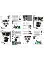
Insert the peeled comm unication cables into the
holes in the connector in correct order.
Blac k (V-)
Blue (C AN_L)
Shie lded cabl e (C AN_SHL D)
Red (V+ )
Whit e (CAN_H )
Tighten the screws on the connector by a slotted
screwdriver, and fix the comm unication cables in
the holes in the connector.
Sc rew by a s lot ted scr ewdri ver.
Use standard 35mm DIN rail.
Mount TAP-CN01/CN02/CN0 3 onto the DIN rail.
OFF
OFF
OFF
TAP-C N01
TAP-C N02
TAP- CN03
Insert the connectors into TAP-CN01/CN02/CN03.
Insert t he connector i nto
TAP-CN0 1 termina l.
Insert t he connector i nto
TAP-CN0 2 termina l.
Insert t he connector i nto
TAP-CN0 3 termina l.
Notes:
1. Use only wires specifically designed for DeviceNet/CANopen for wiring.
2. The terminal screws shall be tightened to 5 .18 kg-cm (4.5 in-lbs).
3. DO NOT place the signal cable and power cable in the same wiring circuit.
Electrical Circuit
TAP-CN01 TAP-CN02
T
B
1
T
B
2
T
h
i
c
k
C
a
b
l
e
T
h
i
c
k
C
a
b
l
e
V+
V+
H H
S S
L L
V-
V-
V+
HSL
V-
1
2
1
¿
TB 3
Th in Ca ble
TB1
TB2
TB5
TB3
TB4
Thic k Cable
Thic k Cable
Thin C able
Thin C able
V+ V+ V+
H H H
S S S
L L L
V- V- V-
V+V+
H HSS LL V-
V-
1
2
1
¿
TAP-CN03
T
B
1
T
B
2
T
h
i
c
k
C
a
b
l
e
T
h
i
c
k
C
a
b
l
e
V+
V+
H H
S S
L L
V-
V-
1
2
1
¿
TB3
TB4
TB5
8 87 76 65 5
4 4
3 3
2 21 1
8 76 5
4
3
2 1
Thin C able
Thin C able
Thin C able
Components
DeviceNet/CANopen Connector
To connect with the DeviceNet/CANopen network, use the connector enclosed with TAP-CN01/02/03 or any
connectors you can buy in the store for wiring.
PIN Signal Description
V- V- 0V DC
L CAN_L Signal-
S SHIELD Shielded cable
H CAN_H Signal+
V+ V+ 24V DC
V-
L
S
H
V+
PIN Signal Description
1 CAN_H Signal+
2 CAN_L Signal-
3 CAN_GND 0V DC
4 RESE_1 Reserved
5 RESE_2 Reserved
6 CAN_SHLD Shielded cable
7 CAN_GND 0V DC
8 CAN_V+ 24V DC
1
2
34
5
678
Termination Resistance Setup Switch
ON
OF F
The termination resistance switch is used for determining whether the resistance is valid.
ON = valid; OFF = invalid.
Termination Resistance
TAP-CN01/CN02/CN03 formulates a 121Ω termination resistance.
Connection Example
Establishing a network through TAP-CN01/CN02/CN03:
TAP-CN02
TAP-CN01
TAP-CN03
Main cable
Main cable Main cable
Sub cable
Sub cable
Sub cable
S
u
b
c
a
b
l
e
S
u
b
c
a
b
l
e
S
u
b
c
a
b
l
e
To install TAP-CN01/CN02/CN03 in the starting point or end of the network, you have to switch ON the
termination resistance. To install TAP-CN01/CN0 2/CN03 in the middle of the network, you have to switch
OFF the termination resistance.
When using TAP-CN01/CN02/CN03 to establish a DeviceNet/CANopen network, the sub cable cannot be
longer than 6m.
(OPEN TYPE) /
( )
/
TAP-CN01/CN02/CN03 TAP-CN01/CN02/CN03 DeviceNet CANope n
DeviceNet CANopen TB1 TB2 TB3 ~ T B5
TAP-CN01/CN02/CN03 121 SW
VX.X XXX
MADE IN X XXXXX
RTU DEN T00T 720 000 1
MADE IN X XXXXX
CN0 1000 0W7 25000 1
CN0X0 00
W
0001
0
7
25
1
DeviceNet/CANopen
2
DeviceNet/CANopen
3
DeviceNet/CANopen
4
5
121
1
2
3
4
5
6
66.50[2 .62]
87.00[3 .43]
mm
6
DIN
1
DeviceNet/CANopen
2
DeviceNet/CANopen
3
DeviceNet/CANopen
4
DeviceNet/CANopen
5
DeviceNet/CANopen
6
7
121
1
2
3
4
5
6
7
8
96.50[ 3.80]
97.00[3.43 ]
mm
8
DIN
DeviceNet
11 ~ 25V DC
/
0ºC ~ 55ºC 50 ~ 95% 2
-25ºC ~ 70ºC 5 ~ 95%
30mm
2
2 1
1
DeviceNet/CANopen
2
DeviceNet/CANopen
3
DeviceNet/CANopen
4
DeviceNet/CANopen
5
DeviceNet/CANopen
6
7
121
5
6
7
8
1
2
3
4
66. 50[ 2.62 ]
66. 50[2. 62]
mm
8
DIN

35mm DIN
TAP-CN01/CN02/CN03 DIN
OFF
OFF
OFF
TAP-CN01
TAP-CN02
TAP-CN03
TAP-CN01/CN02/CN03
1. DeviceNet/C ANopen
2. 5.18 kg-cm (4.5 Ib-in)
3.
TAP-CN01 TAP-CN02
T
B
1
T
B
2
T
h
i
c
k
C
a
b
l
e
T
h
i
c
k
C
a
b
l
e
V+ V+
H H
S S
L L
V- V-
V+
H
S
L
V-
1
2
1
¿
TB3
Thi n Ca ble
TB 1 T B2
TB 5TB 3 T B4
Th ick Ca ble
Th ick Ca ble
Th in C ab le
Th in C ab le
V+ V+ V +
H H H
S S S
L L L
V- V- V-
V+V+H HSS L
L
V-V-
1
2
1
¿
TAP-CN03
T
B
1
T
B
2
T
h
i
c
k
C
a
b
l
e
T
h
i
c
k
C
a
b
l
e
V+ V+
H H
S S
L L
V- V-
1
2
1
¿
TB3
TB4
TB5
8 87 76 65 54 43 32 21 1 876 5 4 3 2 1
Thin Cabl e
Thin Cabl e
Thin Cabl e
DeviceNet/CANopen
DeviceNet/CANopen TAP-CN01/CN02/CN03
V- V- 0V DC
L CAN_L Signal-
S SHIELD
H CAN_H Signal+
V+ V+ 24V DC
V-
L
S
H
V+
1 CAN_H S ignal+
2 CAN_L Signal-
3 CAN_GND 0V DC
4 RESE_1
5 RESE_2
6 CAN_SHLD
7 CAN_GND 0V DC
8 CAN_V+ 24V DC
1
2
34
5
678
ON
OF F
SW SW ”ON”
SW ”OFF”
TAP-CN01/CN02/CN03 121
TAP-CN01/CN02/CN03
TAP-CN01/CN02/CN03 ”ON”
TAP-CN01/CN02/CN03 ”OFF”
TAP-CN01/CN02/CN03 DeviceNet/C ANopen 6m
(OPEN TYPE) /
( )
/
TAP-CN01/CN02/CN03 TAP-CN01/CN02/CN03 De viceNet C ANopen
DeviceNet CANopen TB1 TB2 TB3 ~ TB5
TAP-CN01/CN02/CN03 121 SW
VX.X XXX
MADE IN X XXXXX
RT UDEN T00T 720 000 1
MADE IN X XXXXX
CN0 1000 0W7 25000 1
CN 0X0 00
W
00 01
0
7
25
( 2007
)
( W: T: )
1
DeviceNet/CANopen
2
DeviceNet/CANopen
3
DeviceNet/CANopen
4
5
121
1
2
3 4
5
6
66 .50 [2.6 2]
87. 00[ 3.4 3]
mm
6
DIN
1
DeviceNet/CANopen
2
DeviceNet/CANopen
3
DeviceNet/CANopen
4
DeviceNet/CANopen
5
DeviceNet/CANopen
6
7
121
1
2
3
4
5
6
7
8
96.50 [3.80]
97.00[ 3.43]
mm
8
DIN
1
DeviceNet/CANopen
2
DeviceNet/CANopen
3
DeviceNet/CANopen
4
DeviceNet/CANopen
5
DeviceNet/CANopen
6
7
121
5
6
7
8
1
2
3
4
66. 50[ 2.6 2]
66. 50[2 .62 ]
mm
8
DIN
DeviceNet
11 ~ 25V DC
/
0ºC ~ 55ºC 50 ~ 95% 2
-25ºC ~ 70ºC 5 ~ 95%
30mm
30mm
2
2 1
( CAN_L)
( CAN_SHLD)
(
V
- )
(V+)
(CAN_H)
35mm DIN
TAP-CN01/CN02/CN03 DIN
OFF
OFF
OFF
TAP -CN01
TAP -CN02
TAP- CN03
TAP-CN01/CN02/CN03
1. DeviceNet/CANopen
2. 5.18 kg-cm (4.5 Ib-in)
3.
TAP-CN01 TAP-CN02
T
B
1
T
B
2
T
h
i
c
k
C
a
b
l
e
T
h
i
c
k
C
a
b
l
e
V+ V+
H H
S S
L L
V- V-
V+
HSL
V-
1
2
1
¿
TB3
Thi n Ca ble
TB 1
TB 2
TB 5
TB 3
TB 4
Th ick Ca ble
Th ick Ca ble
Th in C ab le
Th in C ab le
V+ V + V +
H H H
S S S
L L L
V- V- V-
V+V+
H HSS LL V-
V-
1
2
1
¿
TAP-CN03
T
B
1
T
B
2
T
h
i
c
k
C
a
b
l
e
T
h
i
c
k
C
a
b
l
e
V+
V+
H H
S S
L L
V-
V-
1
2
1
¿
TB3
TB4
TB5
8 87 76 65 5
4 4
3 3
2 21 1
8 76 5
4
3
2 1
Thin Cabl e
Thin Cabl e
Thin Cabl e
DeviceNet/CANopen
DeviceNet/CANopen TAP-CN01/CN02/CN03
V- V- 0V DC
L CAN_L Signal-
S SHIELD
H CAN_H Signal+
V+ V+ 24V DC
V-
L
S
H
V+
ON
OF F
SW SW ”ON”
SW ”OFF”
TAP-CN01/CN02/CN03 121
TAP-CN01/CN02/CN03
TAP-C N02
TAP-C N0
TAP-C N0
TAP-CN01/CN02/CN03 ”ON”
TAP-CN01/CN02/CN03 ”OFF”
TAP-CN01/CN02/CN03 DeviceNet/CANopen 6m
1 CAN_H Signal+
2 CAN_L Si gnal-
3 CAN_GND 0V DC
4 RESE_1
5 RESE_2
6 CAN_S HLD
7 CAN_GND 0V DC
8 CAN_ V+ 24V DC
1
2
34
5
678
-
 1
1
-
 2
2

