
267
操作说明书
Operating Instructions


1
Class 267 Operating Instructions
267 操作说明书
Table of Contents/
目录
1
General ....................................................................................................................................... 6
Class 267- with subclasses.......................................................................................................................... 6 1.1
References and illustration .......................................................................................................................... 6 1.2
Instaling the belt guard (see fig. 1 and 2) .................................................................................................... 6 1.3
Taking into service ....................................................................................................................................... 6 1.4
2
Control elements and functional elements on the sewing machine ................................................. 7
Basic equipment of the subclass 267 .......................................................................................................... 7 2.1
Basic equipment of further subclasses ........................................................................................................ 7 2.2
3
Instructions for sewing .................................................................................................................. 7
Needle .......................................................................................................................................................... 7 3.1
3.1.1
Needle change ......................................................................................................................................... 7
Threads ........................................................................................................................................................ 7 3.2
3.2.1
Threading of needle thread ...................................................................................................................... 8
Thread tension ............................................................................................................................................. 8 3.3
3.3.1
Adjusting the thread tensions................................................................................................................... 8
3.3.2 Lifting the thread tension .......................................................................................................................... 9
Bobbin thread ............................................................................................................................................... 9 3.4
3.4.1
Winding the bobbin thread (fig. 3) ............................................................................................................ 9
3.4.2 Bobbin change ......................................................................................................................................... 9
3.4.3 Adjusting the bobin thread tension .......................................................................................................... 9
Presser foot ................................................................................................................................................ 10 3.5
3.5.1
Lifting the presser foot ........................................................................................................................... 10
3.5.2 Regulating the presser foot .................................................................................................................... 10
3.5.3 Changing the presser foot ...................................................................................................................... 10
Feed ........................................................................................................................................................... 10 3.6
3.6.1
Feed dog ................................................................................................................................................ 10
3.6.1.1 Stitch length ................................................................................................................................... 10
3.6.1.2 Stitch regulator ............................................................................................................................... 10
3.6.1.3 Bartacking ...................................................................................................................................... 10
4
Functions-description of further subclasses ................................................................................. 11
Needle feed and alternating top feed ......................................................................................................... 11 4.1
4.1.1
Adjusting the stitch length ...................................................................................................................... 11
4.1.2 Adjusting the alternating top feed .......................................................................................................... 11
5
Maintenance .............................................................................................................................. 11
Cleaning ..................................................................................................................................................... 11 5.1
Oil lubrication (fig. 8) .................................................................................................................................. 11 5.2
5.2.1
Oil qualities............................................................................................................................................. 11

2
1
概述 ........................................................................................................................................... 15
267 机型-分机型 ......................................................................................................................................... 15 1.1
参考件号和图解 .......................................................................................................................................... 15 1.2
安装皮带防护罩(见图 1 及图 2) ............................................................................................................. 15 1.3
投入使用 ..................................................................................................................................................... 15 1.4
2
缝纫机上的控制配件和功能配件 .................................................................................................. 15
267 分机型的基本配件 ............................................................................................................................... 15 2.1
细分机型的基本配件 ................................................................................................................................... 16 2.2
3
缝纫指导 .................................................................................................................................... 16
机针 ............................................................................................................................................................ 16 3.1
3.1.1
机针更换 ............................................................................................................................................. 16
缝纫线 ........................................................................................................................................................ 16 3.2
3.2.1
穿机针线 ............................................................................................................................................. 16
夹线器 ........................................................................................................................................................ 17 3.3
3.3.1
调节夹线器 (图 5).......................................................................................................................... 17
3.3.2 挺线 .................................................................................................................................................... 17
梭芯线 ........................................................................................................................................................ 17 3.4
3.4.1
绕梭芯线 (图 3) ............................................................................................................................. 17
3.4.2 梭芯更换 ............................................................................................................................................. 17
3.4.3 调节梭芯线张力 .................................................................................................................................. 18
压脚 ............................................................................................................................................................ 18 3.5
3.5.1
抬压脚 ................................................................................................................................................ 18
3.5.2 压脚调节 ............................................................................................................................................. 18
3.5.3 压脚更换 ............................................................................................................................................. 18
送料 ............................................................................................................................................................ 18 3.6
3.6.1
送料牙 ................................................................................................................................................ 18
3.6.1.1 针距 ................................................................................................................................................ 18
3.6.1.2 针距扳手 ......................................................................................................................................... 19
3.6.1.3 加固缝 ............................................................................................................................................ 19
4
细分机型的功能描述 ................................................................................................................... 19
针送料及交替上送料 ................................................................................................................................... 19 4.1
4.1.1
针距调节 ............................................................................................................................................. 19
4.1.2 调节交替上送料 .................................................................................................................................. 19
5
维护 ........................................................................................................................................... 19
清洁 ............................................................................................................................................................ 19 5.1
加油润滑 (图 8) ..................................................................................................................................... 19 5.2
5.2.1
润滑油质量 ......................................................................................................................................... 20

3

4

5
Description of proper use or proper application:
The CL267 is a sewing head which can be used for sewing light to medium heavy sewing material. In
general, such sewing material is made up of textile fibres but also leather. Such sewing materials are
used by the clothing and upholstery industry. It would also be possible to make so called technical seams
with these sewing machines. However, for this application the operator of the machine(s) must have the
possible dangers assessed (cooperation with Dürkopp Adler would be welcomed), as such applications
are, on the one hand, relatively rare and, on the other hand, have an immensely wide range of possibilities.
Depending on the results of this assessment suitable safety measures might have to be implemented.
In general, only dry sewing material may be used on this machine. The material must not exceed 10 mm
in thickness when compressed by the lowered needle butt. The material must not contain any hard
objects as eye shields would otherwise have to be worn when operating the machine. However, such eye
shields are currently not available.
In general, the seam will be sewn with sewing threads made of textile fibres in sizes of up to 10/3 NeB
(cotton threads), 10/3 Nm (synthetic thread), or 11/3 Nm (covering twists). Using other threads would also
require an assessment of the related possible dangers and risks in advance, and the implementation,
where necessary, of suitable safety measures.
This sewing machine may only be put up and used in dry and clean rooms. Should the machine be used
in other rooms which are not dry and clean, further measures may have to be taken which have to be
agreed (see EN 60204-31: 1999).
As a manufacturer of industrial sewing machines we assume that operators who are at least semi-skilled
will work at our products, so that it can be assumed that all standard operations and, where applicable,
the dangers are known.
Noise level Lc
Workstation related emission according to DIN 45635-48-A-I-KL2
Subclass: CL267-373
Number of stitches: 1700min
-l
Stitch length: 4,8 mm
Sewing material: 2-play Skai 1,6 mm 900 g/m
2
DIN 53352
Lc = 82 dB (A)

6
1
General
Class 267- with subclasses
1.1
Subclass : 373
Needle system : 134-35
Needle No. : 130
Braided thread Nm : 20/3
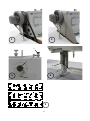
References and illustration
1.2
A functional element mentioned in the text gets a reference (e.g. "A") if it is illustrated in the
appendix.
An electrical or pneumatic functional element bears in all technical documentation (e.g. plan of
electrical or pneumatic system) the same reference (e.g. "s1" or "24.2") as that in the text,
preceding the fraction stroke.
In the attached illustration this reference stands in a circle.
Installing the belt guard (see fig. 1 and 2)
1.3
Taking into service
1.4
- Turn on the main switch,
- Lower the presser foot by the lever B,
- For pulling up the bobbin thread, hold the needle thread behind the
presser foot and rotate the machine,
- Lift the presser foot,
- Place both threads backwards and position the material,
- Lower the presser foot,
- Lower the pedal forwards. The machine will operate faster if the
pedal is lowered more (do not push or pull the material),
- Operate machine without material only with lifted presser foot.
After sewing, turn off the main switch.

7
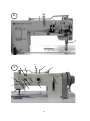
2
Control elements and functional elements on the sewing machine
Basic equipment of the subclass 267
2.1
H Rotary button for regulating main tension of the needle
thread
O Thread guide
L Thread guide
P Adjustable bobbin winder pre-tension
M Bobbin winder with stop lever
I Thread guide
Q Knurled button for regulating the stitch length
B Lever for arresting the sewing foot in its upper position
and for lifting the main tension of the needle thread
E Thread guide
D Thread pulling spring
C Thread guide
Basic equipment of further subclasses
2.2
N Knurled screw with counter-nut for regulating the cloth
presser foot
K Rotary button for adjusting the needle thread pre-tension
G Adjustable thread guide
F Non-adjustable thread guide
3
Instructions for sewing
Needle
3.1
According to the sub-class, see the suitable needle in the table 1.1.
3.1.1
Needle change
- Lift the needle to the upper dead point,
- Loosen screw S and pull out the needle,
- Place the new needle with the short groove towards the hook, introduce it up to the stop and tighten the screw.
Threads
3.2
According to the sub-class, see the maximum limits of the suitable needle and bobbin threads in the table 1.1.

8
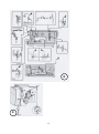
3.2.1
Threading of needle thread
Pass the needle thread according to fig. 9.
- through the reel stand,
- from right through the thread guide O,
- from right through the upper hole in the thread guide L,
- from left through the middle hole of the thread guide L,
- from right through the lower hole of the thread guide L,
- counter-clockwise around the adjustable needle thread pre-tension K
- back through the lower hole of the thread guide I,
- clockwise over the thread guide I,
- counter-clockwise in the adjustable needle thread main tension H, clockwise in the thread guide F,
up to the hook,
- from outside below the pulling spring D,
- from below behind the thread guide E,
- from below behind the adjustable thread guide G,
- from right through the lower hole in the thread take-up lever,
- from above through the thread guide E (if available),
- behind the thread guide C,
- through the thread guide R,
- to the hook through the needle and advance some 8,0 cm
Thread tension
3.3
3.3.1
Adjusting the thread tensions
Rule 1:
A good seam pattern with regularly tightened stitches is often obtained only by regulating the needle
thread tensioning elements, principally by the needle thread main tension H.
Indication 1:
When adapting the needle thread tension, loosen first the needle thread pre-tension K and regulate only
the needle thread main tension H, until the bobbin thread and the needle thread are locked in the material,
fig. 5.
The needle thread pre-tension should be regulated finally, because it is always lower than the main
tension of the needle thread.
Rule 2:
In case of a general adjustment of the thread tensioning elements, adjust first the bobbin thread tension P
for a low value and adapt it then to the needle thread tension.
Indication 2:
For a lockstitch seam, the low bobbin thread tension can already be influenced during the winding
process by the adjustable bobbin winder pre-tension P. The bobbin thread pre-tension P should be
adjusted so that the bobbin thread is wound regularly with the lowest possible tension.

9
3.3.2
Lifting the thread tension
- automatically with the "presser foot lift"
Bobbin thread
3.4
According to the sub-class, see the maximum limits of the suitable
bobbin thread in the table 1.1.
3.4.1
Winding the bobbin thread (fig. 3)
Pass the bobbin thread
- through the reel stand,
- from left through the rear hole in the thread guide U,
- clockwise between the disks around the adjustable bobbin winder
pre-tension U,
- from right back through the rear hole in the thread guide U,
- from left through the middle hole in the thread guide U,
- from right through the front hole in the thread guide U,
- counter-clock wise several times around the bobbin T,
- pass the excessive thread end in the knife for cutting it off,
- press the bobbin winder lever M. The winder will stop automatically.
- Pull the bobbin thread in the knife for cutting it off.
The bobbin winder pre-tension U should be set so Low that the thread is wound regularly at low tension.
When winding at an excessive pre-tension, the aluminium bobbins T may be separated and
considerable thread cutting disturbances may occur.
3.4.2
Bobbin change
For changing the bobbin,
- Move the thread take-up lever to its topmost point,
- Swing the lever B upwards (for arresting the presser foot in its upper position),
- Lift the flap and remove the bobbin case top from the hook,
- Place the other bobbin so that the bobbin rotates contrary to the thread pulling direction,
- Pull the bobbin thread under the spring d in the slit and advance
it from below through the hole for about 8,0 cm,
- Hold the bobbin case top with bobbin at the free thread end and place it into the hook,
close the fIap.
3.4.3
Adjusting the bobbin thread tension
Rule 1:
Work with the lowest possible bobbin thread tension.
Indication 1:
For correcting, turn the screw.
Rule 2:
For a lockstitch seam, the low bobbin thread tension can already be influenced during the winding

10
process by the adjustable bobbin winder pre-tension U.
Indication 2:
The bobbin thread pre-tension U should be adjusted so that the bobbin thread is wound regularly with the
lowest possible tension.
Presser foot
3.5
3.5.1
Lifting the presser foot
-by knee lever in basic equipment
The lifted presser foot can be arrested in its upper position by
turning the lever B.
3.5.2
Regulating the presser foot
- by the knurled screw N, according to the equipment
Turn clockwise for higher pressure
Turn counter-clockwise for lower pressure
3.5.3
Changing the presser foot
- Arrest the presser foot in its upper position by turning the lever B,
- Move the needle to its upper dead point
- Loosen the screw and pull off the presser foot,
Fit the other presser foot in inverted sequence.
Feed
3.6
3.6.1
Feed dog
3.6.1.1
Stitch length
- For adjusting the stitch length, turn the knurled handle Q.
Turn clockwise = for reducing the stitch length
Turn counter-clockwise = for increasing the stitch length
3.6.1.2
Stitch regulator
- Lift the stitch regulator Q for sewing backwards or for bartacking,
3.6.1.3
Bartacking
- by lifting the stitch regulator lever Q in case of basic equipment,

11
4
Functions-description of further subclasses
Needle feed and alternating top feed
4.1
4.1.1
Adjusting the stitch length
- by the knurled handle Q
4.1.2
Adjusting the alternating top feed
by displacing the traction rod in the coulisse A according to the fabric thickness.
Traction rod downwards = minimum stroke
Traction rod upwards = maximum stroke
For obtaining the maximum stroke, operate the knee switch or the pedal while sewing.
5
Maintenance
Cleaning
5.1
Rule:
In case of full-shift service clean at short intervals, possibly daily, by using a brush.
Indication:
Some materials are inclined to an increased separation of fluff,finishing agents, etc., the sediments of
which are quickly solidified particularly by the pushing and lifting movement of the feed dog, impeding
thus the machine function.
For thorough cleaning remove also the throat plate.
At longer intervals unscrew the head cover and clean the arm head.
Oil lubrication (fig. 8)
5.2
The oil points marked by an arrow as well the outside and inside joints should be lubricated additionally,
preferably when starting the work. In case of a full-shift serviceapply about daily 1 or 2 drops of oil. (At
longer intervals remove also the upper arm cover and head cover) .
Attention:
Prior to the first operation resp. after a longer standstill of the machine all marked positions of machine
must be oiled.
5.2.1
Oil qualities
Recommended is MILLCOT K 68 of ESSO or other brands with following features :
Viscosity at 40°: 65 mm
2
/s
Flash point: 212 °C
This oil can be obtained from the manufacturer:
1 litre - ref. no. 990 47 012 8 or 5 litres - ref. no. 990 47 012 9

12
前 言
本操作说明书用于帮助用户熟悉机器并根据推荐意见使用机器。
操作说明书中包含如何安全、正确及经济地操作机器的重要信息。按照说明书要求
操作,能消除危险、降低修理成本和减少停机时间,增加机器可靠性和使用寿命。
本操作说明书是对现有的事故预防措施和环境保护国家标准的补充。
操作说明书必须始终放在机器/缝纫单元旁,便于查阅。
授权要操作本机器/缝纫单元的工作人员必须阅读和应用本操作手册。
即:
— 操作,包括装配、工作中的故障排除和清除织物垃圾
— 服务(维护、检验、修理)和/或
— 运输
用户还必须保证只有授权人员才可操作本机器。
用户必须至少每班检查一次机器有无明显损坏,对任何影响安全的变化(包括工作
性能)立即报告。
用户必须确保机器操作完全正确。
切勿卸下或弃用安全装置。
如果装配、修理或维护时须卸下安全装置,则修理和维护工作完成后必须立即将安
全装置重新装上。
未经授权擅自改动机器,由此造成机器损坏,制造商不承担责任。
须遵守在机器/缝纫单元上有关安全和危险的所有警示。黄黑色条框表示永久危险
区域,如有遭受压伤、割伤、剪伤或碰伤的危险。
除本操作说明书的要求外,还须遵守一般安全和事故预防规则!

13
一般安全说明
不遵守以下安全说明会导致人身伤害或机器损坏。
1. 机器只能由充分了解操作说明书的人员调试并由受过专业培训人员操作。
2. 投入使用之前须阅读安全规则以及马达供应商的使用手册。
3. 只能按规定的用途使用机器。没有安全装置的机器不得使用。遵守所有相关的安全
规定。
4. 更换标准零件(如针、压脚、针板、送料牙和梭芯)时;穿线时;离开工作场所时
以及维护保养时必须关闭主开关,断开电源或拔下电源插头。
5. 日常保养只能由经过相应培训的人员进行。
6. 修理、调换零件和特殊维修只能由技术人员或经过专业培训的人员进行。
7. 气动系统保养和修理时,应把机器同压缩空气供应系统(最高压力 7-10 bar)断开。
断开前, 降低维修装置的气压。经过专业培训的技术人员仅对机器进行调整和功
能检查的情况例外。
8. 对电气设备的有关工作必须由电气技术人员或经过专业培训的人员进行。
9. 不允许在通电情况下对零件和系统进行工作。DIN VDE 0105 中有具体规定的情况除
外。
10. 机器的转换和变更必须经过我们的授权且只有遵守所有的安 全准则情况下
进行。
11. 修理时只能使用经我们批准的替换零件。
12. 在证实整个缝纫单元符合 EC 条例之前,严禁使用缝纫机。
13. 电源线必须配有与具体所在国规定相应的电源主插头。
这项工作必须由经过专业培训的技术人员进行(见第 8 段 )。
绝对有必要遵守标有这些标志的安全说明
防止人身伤害!
还请注意一般安全说明

14
正确使用或正确应用说明
267 型机头可用于缝纫轻薄至中厚缝料。一般而言,这类缝料是纺织纤维也可以是皮革材料,这类缝料应用
于服装和室内装潢工业。使用这种缝纫机还能缝出所谓的技术线缝,然而对于这类应用,机器操作工必须评估
可能产生的风险(DÜRKOPP ADLER 非常愿意与之合作), 因为这类应用一方面相对而言非常少见,另一方面
又具有巨大的使用可能性。根据对这一风险评估的结果,必须采取相应的安全措施。
一般而言,该缝纫机只能缝纫干燥面料。当放下机针,压紧状态的缝料厚度绝不能超过 10mm(单针)或 7 mm
(双针)。操作机器时,缝料中决不能含有任何硬物,否则缝纫机头必须另外配备眼睛保护装置,而目前没有这
类装置。
通常,线迹由纺织纤维规格高达 10/3NeB(棉线)、10/3Nm(合成纤维线)或 11/3 Nm (绷线)形成。如果
使用其他线,则事先必须对由此可能产生的危险和风险进行评估, 必要时,必须采取适当的安全措施。
这类缝纫机只能在干燥和干净的室内放置和使用。如果缝纫机在不具备干燥和干净的其他场所使用,则有必
要进一步采取符合要求(见 EN 60204-31;1999)的预防措施。
作为工业缝纫机的制造商,我们认为操作我们产品的人员至少是半熟练操作工,所以可以认为其了解所有的
标准操作和由此所产生的危险。
噪音等级
Lc
有关工作场所的排放参见 DIN 45635-48-A-I KL2
副型号: -373
针数: 1700min﹣
1
针距: 4.8mm
缝纫面料: 2 层人造革 1.6mm 900 g/m
2
DIN 53352
Lc= 82dB(A)

15
1
概述
267 机型-分机型
1.1
分机型
: 373
机针系统 : 134-35
机针号 : 130
辫线 Nm : 20/3
参考件号和图解
1.2
如果功能配件在附录中用图解说明,则其在文本中提到时就有一个参考件号(如“A”)。
在所有技术文件(如电气或气动系统原理图)中出现的电或气动配件, 其参考件号(如“s1”或“24.2”)
和文本中分数斜杠前的参考号相同。
在所附图中该类参考件号位于圈内。
安装皮带防护罩(见图 1 及图 2)
1.3
投入使用
1.4
-打开主开关,
-通过 B 扳手放下压脚,
-为了引上梭芯线, 拉住压脚下面的针线并转动机器,
-抬起压脚,
-将 2 根线都放在压脚后面并定位好缝料,
-放下压脚,
-向前踩下踏板, 踏板越向下, 机器运转速度越快 (切勿推拉缝料),
-没有缝料时,仅在压脚抬起时运转机器。
缝纫结束后,关掉主开关。
2
缝纫机上的控制配件和功能配件
267 分机型的基本配件
2.1
H 针线主夹线器的调节旋钮
O 过线
L 过线
P 调节梭芯绕线的预张紧夹线器
M 梭芯绕线器满线跳板
I 过线
Q 调节针距的滚花旋钮
B 使缝纫压脚在上位且松开针线的主夹线器的扳手
E 过线
D 挑线簧
C 过线

16
细分机型的基本配件
2.2
N 带锁紧螺母的送布压脚滚花调节螺钉
K 针线预张紧夹线器滚花调节旋钮
G 可调节过线
F 不可调节过线
3
缝纫指导
机针
3.1
适合各机型的机针参见表 1.1。
3.1.1
机针更换
-机针向上至最高点,
-松开螺钉 S 并取出机针,
-安装新机针, 机针短槽指向旋梭,
机针向上插到底, 并拧紧螺钉 。
缝纫线
3.2
根据各种机型,表 1.1 中列出适合针线和梭芯线的最大限定值。
3.2.1
穿机针线
根据图 9 穿机针线
-线通过线盘架,
-从右侧穿过过线 O
-从右侧穿过过线 L 的上孔,
-从左侧穿过过线 L 的中孔,
-从右侧穿过过线 L 的下孔,
-按逆时针方向环绕可调针线预张紧夹线器 K,
-从背面穿过过线 K 的下孔,
-按顺时针方向越过过线 I,
-按逆时针方向夹入可调节针线主夹线器 H,按顺时针方向绕过过线 F,向上过勾子,
-从下面外面穿过挑线簧 D,
-从后面下面穿过过线 E
-从后面下面,穿过可调节过线 G,
-从右侧通过挑线杆下孔,
-从上方通过过线 E (如果有过线 E 的 话 ),
-经过过线 C 后面,
-经过过线 R,
-过线勾穿过机针并拉出线头约 8.0 cm

17
夹线器
3.3
3.3.1
调节夹线器 (图 5)
规则
1
:
通常只有通过调节针线夹紧件才能获得正常张紧针迹的好线迹, 主要通过调节针线主夹线器 H。
说明
1
:
调节针线夹线器时,首先松开针线预紧夹线器 K,仅调节针线主夹线器 H, 直至梭线和针线交织在缝料中,
图 5.
应最后调节针线预张紧夹线器, 因为针线预张紧力始终小于针线的主张紧力.
规则
2
:
在对夹线构件进行一般调节的情况下,首先调节梭线夹线器 P 至低值,然后调节针线张紧力使之适配。
说明
2
:
对于梭式针迹,在绕线过程中,梭芯线的低张紧力会受到绕线器可调预紧张力夹线器 P 的影响。所以调节
绕线器预紧张力夹线器 P 时,应使梭芯线以可能最低的张力匀称地绕线。
3.3.2
挺线
-由“抬压脚”自动形成
梭芯线
3.4
根据各机型,适用于各梭芯线的最大限定值见表 1.1。
3.4.1
绕梭芯线 (图 3)
抽出梭芯线
-穿过线盘架
-从左侧通过过线 U 的后孔,
-按顺时针方向夹入可调节梭芯绕线器预张紧夹线器 U 之间,
-从右后侧通过过线 U 的后孔,
-从左侧通过过线 U 的中孔,
-从右侧通过过线 U 的前孔,
-逆时针在梭芯 T 上绕若干圈,
-露出多余线头并由割线刀割去。
-推开绕线器满线板 M, 绕线器自动停止。
-拉出梭芯线放入割刀切线。
绕线器预张紧夹线器 U 应设定得较低使线在低张力下有规律地绕线。
在过大的预张紧力下绕线时,铝梭芯 T 可能会分离并可能发生相当多剪线紊乱。
3.4.2
梭芯更换
更换梭芯时,
-把挑线杆提升到最高位置,
-向上扳动扳手 B,(使压脚停在上面位置),
-打开锁扣并从旋梭中取出梭壳,

18
-放入另一梭芯,使梭芯的旋转方向和拉线方向相反,
-从弹簧 d 下的缝隙中拉出梭芯线并从下方穿过孔,抽出约 8.0cm 线头,
-抓住装有梭芯的梭壳,线头不受约束,将其装入旋梭中,
关闭锁扣。
3.4.3
调节梭芯线张力
规则 1:
在最低的梭芯线张力下工作。
说明 1:
调节时, 转动螺钉。
规则 2:
对于梭式针迹,在绕线过程中,梭芯线的低张紧力会受到绕线器可调预紧张力夹线器 U 的影响。
说明 2:
调节绕线器预紧张力夹线器 U 时,应使梭芯线以可能最低的张力匀称地绕线。
压脚
3.5
3.5.1
抬压脚
-通过基本配件中的膝提杆,
通过扳动扳手 B,压脚就能抬起停在上面位置。
3.5.2
压脚调节
-根据配件,通过滚花螺钉 N 调节压脚
顺时针转动加大压力
逆时针转动减小压力
3.5.3
压脚更换
-通过扳动扳手 B,压脚就能抬起停在上面位置,
-使机针移动到上死点
-松开螺钉取下压脚,
-按相反顺序装上其它压脚。
送料
3.6
3.6.1
送料牙
3.6.1.1
针距
-调整针距时, 转动滚花手柄 Q
顺时针转动 = 缩短针距
逆时针转动 = 加长针距
ページが読み込まれています...
ページが読み込まれています...
ページが読み込まれています...
ページが読み込まれています...
ページが読み込まれています...
ページが読み込まれています...
ページが読み込まれています...
ページが読み込まれています...
-
 1
1
-
 2
2
-
 3
3
-
 4
4
-
 5
5
-
 6
6
-
 7
7
-
 8
8
-
 9
9
-
 10
10
-
 11
11
-
 12
12
-
 13
13
-
 14
14
-
 15
15
-
 16
16
-
 17
17
-
 18
18
-
 19
19
-
 20
20
-
 21
21
-
 22
22
-
 23
23
-
 24
24
-
 25
25
-
 26
26
-
 27
27
-
 28
28


DURKOPP ADLER 267 - 2016 取扱説明書
- タイプ
- 取扱説明書
- このマニュアルも適しています
他の言語で
関連論文
その他のドキュメント
-
 ZOJE ZJ0303L-3-D3 Parts Manual
-
Siruba 700Q+ Instruction book
-
-
Philips SA2625/97 取扱説明書
-
-
 Duerkopp Adler 261_vaild_from_december_2019 取扱説明書
-
-
-
-

