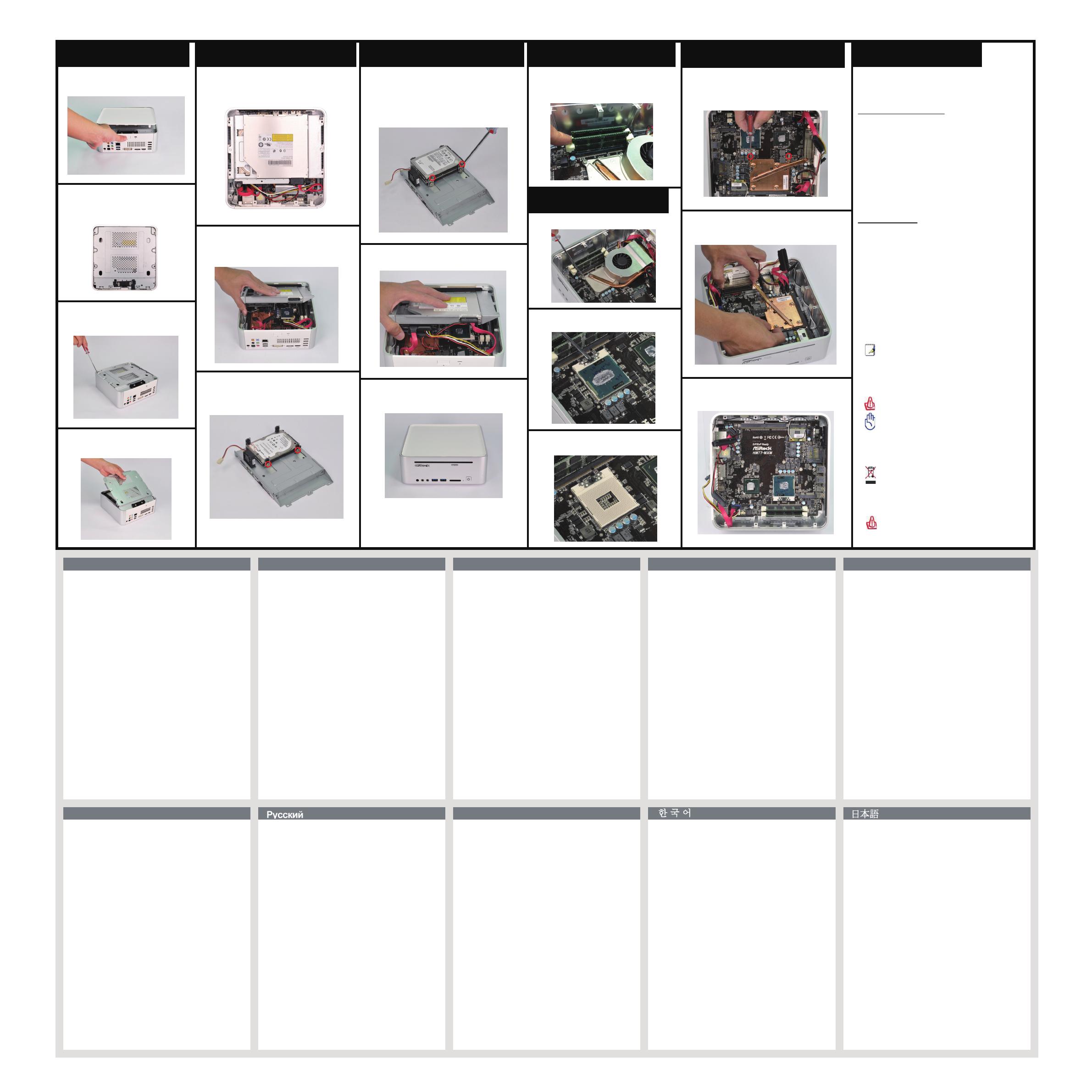
Opening the chassis
English
Español
onailatI siaçnarF hcstueD
sêugutroP
1. Press the button on the rear I/O
to open the top of the chassis.
2. Afte r the c hass i s is o p ened ,
you will see the top shield
inside the chassis.
3. Unsc r e w th e scr e w s on t he
c o rner s of t h e top shield.
4. Care f u lly r emov e the top
shield.
Reinstalling the ODD/HDD
1. After you remove the top shield, you
will see the ODD/HDD bracket.
2. Disc o n nect the O D D/HD D SATA
p o w er c a ble, a nd t a k e ou t the
O D D /HDD brac k e t.
3. Unscrew the screws from the side of
the ODD / HDD rack, and change your
required ODD / HDD.
Installing the second HDD
2. Connect the SATA and power cables.
3. Replace the side cover and fasten
the screws.
1. Please follow step 1 above to remove
the CPU fan. Then unscrew the two
screws on top of the MXM card.
Reinstalling the DIMMs
1. Unlo c k the DIMM s lots b y
p r essi n g th e reta i n ing c lips
o u twar d to c h ange t he D I MMs.
2. Rotate the screw on the top of the
CPU socket.
Opening the chassis
1. Press the button on the rear I/O to open the top of the chassis.
2. After the chassis is opened, you will see the top shield inside the chassis.
3. Unscrew the screws on the corner of the top shield.
4. Carefully remove the top shield.
Reinstalling the ODD/HDD
1. After you remove the top shield, you will see the ODD/HDD bracket.
2. Disconnect the ODD/HDD SATA power cable, and take out the
ODD/HDD bracket.
3. Unscrew the screws from the side of the ODD / HDD rack, and
change your required ODD / HDD.
Installing the second HDD
1. Please follow steps 1 and 2 above to take out the ODD/HDD
bracket. Install the second HDD and fasten the screws to the
rack, then replace the bracket into the chassis.
2. Connect the SATA and power cables.
3. Replace the side cover and fasten the screws.
Reinstalling the DIMMs
1. Unlock the DIMM slots by pressing the retaining clips outward to change
the DIMMs.
Reinstalling the CPU
1. Unscrew the screws of the CPU fan.
2. Rotate the screw on the top of the CPU socket.
3. Now you can reinstall a new CPU to the system.
Reinstalling the MXM card
1. Please follow step 1 above to remove the CPU fan. Then unscrew
the two screws on top of the MXM card.
2. Lift the MXM card slightly upwards, then gently pull it out of the
MXM slot.
3. Now you can reinstall a new MXM card to the system.
打開機箱
1. 按後面I/O面板上的按鈕以利打開塑膠上蓋的頂部。
2. 上蓋打開後, 您會在機箱內看到鐵上蓋。
3. 擰開鐵上蓋各個螺絲。
4. 小心的取下鐵上蓋。
重新安裝光碟機/硬碟
1. 取下鐵上蓋後, 您會看到光碟機/硬碟托盤架子。
2. 拔掉光碟機/硬碟的SATA電源線後, 即可順利取出光碟機/硬碟托架。
3. 擰開光碟機/硬碟的螺絲後,即可更換新的光碟機/硬碟。
安裝第二顆硬碟
1. 請先按照上述步驟一至二移除光碟機/硬碟托盤架子。安裝第二顆硬
碟並且以螺絲固定兩側,再將托架放回機箱內。
2. 連接SATA和電源線。
3. 裝回上蓋並且以螺絲固定。
重新安裝DIMM
1. 扳開兩側記憶體固定夾後,即可更換記憶體。
重新安裝CPU
1. 擰開CPU散熱模組的螺絲。
2. 旋轉CPU固定螺絲。
3. 現在您就可以更換安裝你所需的CPU到系統。
重新安裝MXM顯示卡
1. 按照上述步驟一移除CPU散熱模組。擰開MXM顯示卡上方兩顆螺絲。
2. 將MXM顯示卡微拉向上,再小心地拔出MXM插槽。
3. 現在您就可以更換安裝你所需的MXM顯示卡到系統。
Gehäuse öffnen
1. Drücken Sie zum Öffnen der oberen Gehäuseblende die Taste am
hinteren E/A.
2. Nachdem das Gehäuse geöffnet ist, sehen Sie die obere Abdeckung
im Inneren des Gehäuses.
3. Lösen Sie die Schrauben in den Ecken der oberen Abdeckung.
4. Nehmen Sie die obere Abdeckung vorsichtig heraus.
Neue ODD/HDD installieren
1. Nachdem Sie die obere Abdeckung entfernt haben, sehen Sie die
ODD-/HDD-Halterung.
2. Ziehen Sie das ODD-/HDD-SATA-Netzkabel; nehmen Sie die
ODD-/HDD-Halterung heraus.
3. Lösen Sie die Schrauben von der Seite des ODD/HDD-Rack, wechseln
Sie das/die erforderliche ODD/HDD.
Installation der zweiten HDD
1. Bitte nehmen Sie die ODD/HDD-Halterung anhand der Schritte 1 und 2
oben heraus. Installieren Sie die zwei HDD, ziehen Sie die Schrauben
am Rack fest, bringen Sie die Halterung dann wieder im Gehäuse an.
2. Schließen Sie die SATA- und Netzkabel an.
3. Bringen Sie die seitliche Abdeckung wieder an, befestigen Sie die
Schrauben.
Neue DIMMs installieren
1. Lösen Sie den DIMM-Steckplatz, indem Sie die Halteklammern zum
Auswechseln des DIMM nach außen drücken.
Neue CPU installieren
1. Lösen Sie die Schrauben des CPU-Kühlers.
2. Drehen Sie die Schrauben oberhalb des Prozessorsockels (CPU,
central processing unit).
3. Nun können Sie eine neue CPU im System installieren.
Neue MXM-Karte installieren
1. Bitte entfernen Sie den CPU-Lüfter anhand von Schritt 1 oben. Lösen Sie
dann die bedien Schrauben an der Oberseite der MXM-Karte.
2. Heben Sie die MXM-Karte leicht nach oben an, ziehen Sie sie
anschließend vorsichtig aus dem MXM-Steckplatz.
3. Installieren Sie nun die neue MXM-Karte im System.
Ouverture du châssis
1. Appuyez sur le bouton sur la panneau E/S arrière pour ouvrir la face
supérieure du châssis.
2. Une fois que le châssis est ouvert, vous pouvez voir la plaque de
protection supérieure dans le châssis.
3. Dévissez les vis sur le coin de la plaque de protection supérieure.
4. Sortez soigneusement la plaque de protection supérieure.
Réinstallation de l’unité optique/du disque dur
1. Après avoir retiré la plaque de protection supérieure, vous pouvez voir le
suppport pour unité optique/disque dur.
2. Débranchez le câble d’alimentation SATA pour unité optique/disque dur,
et sortez le support pour unité optique/disque dur.
3. Dévissez les vis situées sur le côté du rack pour ODD / HDD, puis
remplacez l’ODD / HDD tel que requis.
Installation du second disque dur
1. Veuillez suivre les étapes 1 et 2 ci-dessus pour retirer le support du
disque optique/disque dur (ODD/HDD). Installez le second HDD et vissez
les vis au rack, puis replacez le support dans le châssis.
2. Branchez le câble SATA et le câble d’alimentation.
3. Replacez le panneau latéral et revissez les vis.
Réinstallation des modules DIMM
1. Déverrouillez l’emplacement pour module DIMM en appuyant sur les
clips de fixation de façon à les écarter vers l’extérieur pour changer le
module DIMM.
Réinstallation du processeur
1. Dévissez les vis du ventilateur du processeur.
2. Faites tourner la vis située en haut du socket du processeur.
3. Vous pouvez maintenant installer le nouveau processeur dans le système.
Réinstallation de la carte MXM
1. Veuillez suivre l’étape 1 ci-dessus pour retirer le ventilateur du CPU.
Dévissez ensuite les deux vis sur le dessus de la carte MXM.
2. Soulevez légèrement la carte MXM, puis retirez-la délicatement de la
fente MXM.
3. Vous pouvez maintenant insérer une nouvelle carte MXM dans le système.
Apertura del telaio
1. Premere il tasto sul pannello I/O posteriore per aprire la parte superiore
del telaio.
2. Dopo avere aperto il telaio, si vedrà la protezione superiore all’interno.
3. Togliere le viti sugli angoli della protezione superiore.
4. Estrarre delicatamente la protezione superiore.
Installazione dell’unità ODD/HDD
1. Dopo avere rimosso la protezione superiore si vedrà il supporto
ODD/HDD.
2. Scollegare il cavo d’alimentazione ODD/HDD SATA ed estrarre il
supporto ODD/HDD.
3. Svitare le viti dal lato del rack ODD / HDD e cambiare l'ODD / HDD
richiesto.
Installazione della seconda unità HDD
1. Attenersi alle istruzioni dei precedenti punti 1 e 2 per estrarre la staffa
ODD/HDD. Installare il secondo HDD e fissare le viti al rack, quindi
rimettere la staffa nel telaio.
2. Collegare il cavo SATA ed i cavi di alimentazione.
3. Riposizionare la copertura laterale e fissare le viti.
Installazione dei moduli DIMM
1. Sbloccare l’alloggio DIMM premendo verso l’esterno i fermagli ed
installare il modulo DIMM.
Installazione della CPU
1. Togliere le viti della ventola CPU.
2. Ruotare la vite sulla parte superiore del socket CPU.
3. Adesso si può installare la nuova CPU sul sistema.
Installazione della scheda MXM
1. Attenersi alle istruzioni del precedente punto 1 per rimuovere la ventola
CPU. Togliere le due viti sulla parte superiore della scheda MXM.
2. Sollevare leggermente verso l'alto la scheda MXM, poi estrarla
delicatamente dall’alloggio MXM.
3. Adesso si può installare la nuova scheda MXM sul sistema.
Apertura del chasis
1. Pulse el botón situado en el panel posterior de E/S para abrir la parte
superior del chasis.
2. Una vez abierto el chasis, podrá ver la cubierta protectora superior en
su interior.
3. Desenrosque los tornillos situados en las esquinas de la cubierta
protectora superior.
4. Extraiga la cubierta protectora superior con cuidado.
Sustitución de la unidad ODD/HDD
1. Una vez extraída la cubierta protectora superior, podrá ver la
abrazadera de la unidad ODD/HDD.
2. Desconecte el cable de alimentación SATA de la unidad ODD/HDD
instalada y extraiga la abrazadera de la unidad ODD/HDD.
3. Quite los tornillos del lateral del bastidor de la unidad de disco óptico
(ODD, Optical Disk Drive) y la unidad de disco duro (HDD, Hard Disk
Drive) y cambie la ODD / HDD que requiera.
Instalación de la segunda unidad HDD
1. Siga los pasos anteriores 1 y 2 para extraer el soporte de Unidad de A
Disco óptico/Unidad de Disco Duro (ODD/HDD). Instale la segunda
unidad de disco duro y apriete los tornillos en el bastidor y a
continuación, vuelva a colocar el soporte en la caja.
2. Conecte los cables de alimentación y SATA.
3. Vuelva a colocar la tapa lateral y apriete los tornillos.
Sustitución de los módulos DIMM
1. Desbloquee una ranura DIMM presionando las pinzas de retención
hacia fuera y sustituya el módulo DIMM correspondiente.
Sustitución de la CPU
1. Desenrosque los tornillos del ventilador de la CPU.
2. Gire el tornillo situado en la parte superior del zócalo de la CPU.
3. Ahora podrá instalar una nueva CPU en el sistema.
Sustitución de la tarjeta MXM
1. Siga el paso anterior 1 para extraer el ventilador de la CPU. Luego,
extraiga los dos tornillos de la parte superior de la tarjeta MXM.
2. Levante la tarjeta MXM ligeramente hacia arriba y luego tire de ella
suavemente, extrayéndola de la ranura MXM.
3. Ahora puede volver a instalar una nueva tarjeta MXM en el sistema.
Процедура открытия корпуса
1. Нажмите кнопку на задней панели ввода-вывода, чтобы открыть
верхнюю часть корпуса.
2. После открытия корпуса будет виден верхний экран, расположенный
внутри корпуса.
3. Отвинтите винты в углах верхнего экрана.
4. Осторожно извлеките верхний экран.
Процедура замены привода оптических дисков и жестких дисков
1. После удаления верхнего экрана будет виден кронштейн для
привода оптических дисков и жестких дисков.
2. Отсоедините кабель питания SATA привода оптических дисков и
жестких дисков и извлеките кронштейн для привода оптических
дисков и жестких дисков.
3. Выньте винты из боковой панели кармана для оптического/ жесткого
(ODD/HDD) диска и смените обязательный оптический/ жесткий
(ODD/HDD) диск.
Установка второго жесткого диска
1. Выполните вышеуказанные действия 1 и 2 для извлечения скобы
для ODD/HDD. Установите второй жесткий диск и прикрепите винты
к планке, затем установите скобу в системный блок.
2. Подключите кабель SATA и сетевой шнур.
3. Установите на место боковую крышку и затяните винты.
Процедура замены модулей памяти DIMM
1. Откройте гнездо DIMM, нажатием раскрыв фиксаторы наружу,
чтобы заменить модуль памяти DIMM.
Процедура замены центрального процессора
1. Отвинтите винты вентилятора центрального процессора.
2. Поверните винт на верхней панели центрального процессора.
3. Теперь можно установить в систему новый центральный
процессор.
Замена MXM-карты
1. Выполните вышеуказанное действие 1 для извлечения вентилятора
процессора. Открутите два винта, расположенные сверху карты МХМ.
2. Приподнимите карту MXM слегка вперед, затем осторожно извлеките
ее из разъема МХМ.
3. Теперь можно установить новую карту МХМ в систему.
Abrir o chassis
1. Prima o botão E/S na traseira para abrir a parte superior do chassis.
2. Depois de abrir o chassis, irá ver a protecção superior no interior do
chassis.
3. Desaperte os parafusos no canto da protecção superior.
4. Remova a protecção superior com cuidado.
Reinstalar a Unidade de Disco Óptico/Disco Rígido
1. Depois de remover a protecção superior, irá ver o suporte da Unidade
de Disco Óptico/Disco Rígido.
2. Desligue o cabo de alimentação SATA da Unidade de Disco
Óptico/Disco Rígido e retire o suporte da Unidade de Disco
Óptico/Disco Rígido.
3. Desaperte os parafusos da parte lateral do suporte da unidade ODD /
HDD e retire a unidade ODD / HDD.
Instalação da Segunda HDD
1. Siga os passos 1 e 2 indicados acima para retirar o suporte de
ODD/HDD. Instale o Segundo HDD e aperte os parafusos na estrutura
e depois volte a colocar o suporte no chassis.
2. Ligue os cabos SATA e de alimentação.
3. Volte a colocar a cobertura lateral e aperte os parafusos.
Reinstalar os módulos DIMM
1. Abra a ranhura DIMM pressionando para fora os clipes de retenção
para trocar o módulo DIMM.
Reinstalar a CPU
1. Desaperte os parafusos da ventoinha da CPU.
2. Rode o parafuso no cimo do socket da CPU.
3. Pode agora instalar uma nova CPU no seu sistema.
Reinstalar a placa MXM
1. Siga o passo 1 indicado acima para remover a ventoinha da CPU. Em
seguida, desaperte os dois parafusos da parte superior da placa MXM.
2. Levante ligeiramente a placa MXM e retire-a cuidadosamente da
ranhura MXM.
3. Pode agora instalar uma nova placa MXM no sistema.
섀시 열기
1. 뒷면 I/O의 버튼을 눌러 섀시의 위쪽을 고정합니다.
2. 섀시가 열리면 섀시 내부의 상부 쉴드가 보입니다.
3. 상부 쉴드 귀퉁이의 나사를 풀어 줍니다.
4. 상부 쉴드를 조심스럽게 꺼냅니다.
ODD/HDD 재설치하기
1. 상부 쉴드를 제거하면 ODD/HDD 브래킷이 보입니다.
2. ODD/HDD SATA 전원 케이블을 분리하고 ODD/HDD 브래킷을
꺼냅니다.
3. ODD/HDD 랙의 측면에서 나사를 풀고, 필요한 ODD/HDD를 교체합니
다.
보조 HDD 설치하기
1. 위의 단계 1과 2에 따라 ODD/HDD 브래킷을 제거합니다. 두 번째 HDD
를 설치하고 나사로 랙에 고정한 다음, 브래킷을 섀시에 원래대로 고정
합니다.
2. SATA와 전원 어댑터를 연결합니다.
3. 측면 커버를 원위치에 설치하고 나사를 조입니다.
DIMM 재설치하기
1. 고정 클립을 바깥쪽으로 눌러 DIMM 슬롯의 잠금을 해제해 DIMM을
교환합니다.
CPU 재설치하기
1. CPU 팬의 나사를 풀어 줍니다.
2. CPU 소켓 상단의 나사를 돌립니다.
3. 이제 새 CPU를 시스템에 재설치할 수 있습니다.
MXM 카드 재설치하기
1. 위의 단계 1에 따라 CPU 팬을 제거합니다. 그러고서 MXM 카드 상단의
나사 두 개를 풉니다.
2. MXM 카드를 위로 살짝 들어올린 다음, 천천히 당겨 MXM 슬롯에서 빼
냅니다.
3. 이제 새 MXM 카드를 시스템에 다시 설치할 수 있습니다.
シャーシを開ける
1. 背面I/Oのボタンを押してシャーシの上部を開けます。
2. シャーシを開けると、シャーシの内側のトップシールドが見えます。
3. トップシールドの角にあるねじを外します。
4. トップシールドをゆっくりと取り外します。
ODD/HDDの交換
1. トップシールドを取り外すと、ODD/HDDブラケットが見えます。
2. ODD/HDD SATA電源ケーブルを取り外し、ODD/HDDブラケットを外し
ます。
3. HDD/ODD ラックの側面からネジを緩め、必要な ODD/HDD を交換しま
す。
2番目のHDDを取り付ける
1. 上の手順 1 と手順 2 に従って ODD/HDD ブラケットを取り出してくだ
さい。2 番目の HDD を取り付けて、ねじを締めてラックに固定します
。次に、ブラケットをシャーシに取り付け直します。
2. SATA ケーブルと電源ケーブルを接続します。
3. サイドカバーを取り付け、ネジを締めます。
DIMMの交換
1. DIMMスロットの保持クリップを外側に押してロックを解除し、DIMM
を交換できるようにします。
CPUの交換
1. CPUファンのねじを外します。
2. CPU ソケット上部のネジを回転します。
3. これで新しいCPUをシステムに設置することができます。
MXMカードの交換
1. 上の手順 1 に従って CPU ファンを取り外してください。次に、MXM
カードの上部にある 2 本のねじを取り外します。
2. MXM カードをわずかに持ち上げて、MXM スロットから丁寧に取り出し
ます。
3. これで、新しい MXM カードをシステムに取り付け直すことができます。
Safety instructions
Yo ur sys te m i s d e si g ne d a n d te st e d t o me et th e
la tes t s ta n da r ds of sa f et y f or i n fo r ma ti on te c hn o lo gy
eq uip men t. Ho w ev e r, to en s ur e yo u r s af et y, it is
im por tan t t ha t y o u r ea d t h e fo ll o wi n g sa fe t y i ns t ru ct io n s.
Set t ing up you r sy ste m
• Rea d a nd fo l lo w a l l i ns t ru ct io n s i n th e d oc u me n ta ti on
bef ore y o u o pe r at e y o ur sy st em .
• Do not u s e t hi s p r od u ct ne ar w a te r o r a h ea t ed so ur ce
suc h a s a r a di a to r .
• Set up t h e s ys t em on a s ta bl e s ur f ac e.
• Ope nin gs on th e c h as s is ar e fo r v e nt il at i on . D o n ot
blo ck or co v er th e se op e ni ng s. Ma k e su re yo u l e av e
ple nty o f s p ac e a r ou n d t he s ys t em fo r ve n ti l at i on . Ne v er
ins ert o b je c ts of an y k i nd i nt o t h e ve nt i la t io n o pe ni n gs .
• Use th is pr o du c t i n e nv i ro nm en t s w it h am b ie n t
tem per at u re s b e tw e en 0˚ C a nd 4 0 ˚C .
• If you u s e a n e xt e ns i on co rd , m ak e s ur e t ha t t h e to ta l
amp ere r a ti n g o f t he de v ic es p l ug g ed i nt o t h e e xt en si o n
cor d d oe s n o t e xc e ed it s a mp er e r a ti ng .
Car e du rin g us e
• Do not w a lk on th e p o we r c or d o r a ll ow a n yt h in g t o re s t
on it.
• Do not s p il l w a te r o r a n y ot he r l i qu id s o n y ou r s ys te m .
• Whe n t he sy s te m i s t u rn e d OF F, a s ma ll a m ou n t o f
ele ctr ic a l c ur r en t s t il l
flo ws. A l wa y s u np l ug al l p ow er , m o de m, a n d n et w or k
cab les f r om th e p o we r o u tl et s b ef o re c le a ni n g t he
sys tem .
• If you e n co u nt e r t he fo l lo wi ng te c hn ic al pr o bl e ms w it h
the pr od u ct , u n pl u g t he po we r c or d a nd c o nt a ct a
qua lif ie d s e rv i ce te c hn i ci an o r y o ur r et a il e r.
• The po we r c o rd or pl u g i s da ma g ed .
• Liq uid h a s b ee n s p il l ed in to t h e s ys te m.
• The sy st e m d oe s n o t f un c ti on p r op e rl y ev e n i f y ou
fol low t h e o pe r at i ng in s tr uc ti o ns .
• The sy st e m w as dr o pp e d o r th e c ab i ne t is da m ag e d.
• The sy st e m p er f or m an c e c ha ng es .
NO T E : T he wa r ra nt y d o es no t a pp l y t o p ro d uc t s th a t h av e
be e n d i sa s se m bl ed by us e rs .
Sa fet y ca ut io ns a nd wa rn in gs
Op tic al Dr i ve Sa f et y I n fo r ma ti on
Op tic al dr i ve s s o ld wi t h t hi s sy s te m c on ta i ns a C LA SS 1
LA SER PR OD U CT .
CA U T IO N : I nv i si bl e l a se r r a di at i on wh e n o pe n . Do no t
st a r e i nt o b e am o r v i ew di r ec tl y w i th op t ic a l in s tr u me n ts .
WA R N IN G : M ak i ng a d ju s tm e nt s o r p er f or m in g p r oc ed u re s
ot h e r t ha n t h os e s pe c if i ed in t h e u se r ’s ma n ua l m ay
re s u lt in ha z ar do u s l as e r e xp os u re . D o n o t a tt em p t t o
di s a ss e mb l e t he o p ti c al dr i ve . F or yo u r s af e ty , h av e t h e
op t i ca l d r iv e s er v ic e d o nl y b y a n a ut h or i ze d s er v ic e
pr o v id e r.
Pr odu ct d is po sa l not ic e
IM P O RT A NT : T h is s y mb o l o f t he c r os s ed ou t w h ee le d b i n
in d i ca t es th a t th e p r od u ct (e le c tr i ca l a n d e le ct r on i c
eq u i pm e nt ) s h ou ld no t b e p l ac ed in mu n ic i pa l w as t e.
Ch e c k l oc a l r eg ul a ti o ns fo r d is p os a l o f e le c tr on i c
pr o d uc t s.
No rdi c Li th iu m Ca uti on s (f or l it hiu m- io n ba tt er ie s )
CA U T IO N ! Da n ge r o f e xp l os i on i f b a tt e ry is in co r re c tl y
re p l ac e d. Re p la ce on l y w it h t he sa m e o r e qu i va le n t t yp e
re c o mm e nd e d b y th e m a nu f ac t ur er . D i sp o se of us ed
ba t t er i es ac c or di n g t o t he ma nu f ac t ur e r’ s i n st ru c ti o ns .
繁體中文
Reinstalling the CPU
1. Unscrew the screws of the CPU fan.
3. Now you can reinstall a new CPU to
the system.
1. Please follow steps 1 and 2 above to
t a ke o u t the O DD/H D D br a c ket.
Install the second HDD and fasten the
screws
to the rack, then
replace the
bracket into the chassis.
2. Lift the MXM card slightly upwards, then
gently pull it out of the MXM slot.
Reinstalling the MXM card
3. Now you can reinstall a new MXM card to
the system.

