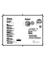
Delta Electronics AC Servo Drive ASDA-B クイックスタートガイド
- タイプ
- クイックスタートガイド

5011650207
2008-11-14
07BQ

English-1
Preface
This quick start will be helpful in the installation, wiring, inspection, and operation of Delta ASDA-B series AC
servo drive and ECMA series servo motor. Before using the product, please read this quick start to ensure
correct use. You should thoroughly understand all safety precautions before proceeding with the installation,
wiring and operation. If you do not understand please contact your local Delta sales representative. Place this
quick start in a safe location for future reference. Please observe the following precautions:
Do not use the product in a potentially explosive environment.
Install the product in a clean and dry location free from corrosive and inflammable gases or liquids.
Do not connect a commercial power supply to the U, V, W terminals of motor. Failure to observe this
precaution will damage either the Servo motor or drive.
Ensure that the motor and drive are correctly connected to a ground. The grounding method must
comply with the electrical standard of the country (Please refer to NFPA 70: National Electrical Code,
2005 Ed.).
Do not disconnect the AC servo drive and motor while the power is ON.
Do not attach, modify or remove wiring when power is applied to the AC servo drive and motor.
Before starting the operation with a mechanical system connected, make sure the emergency stop
equipment can be energized and work at any time.
Do not touch the drive heat sink or the servo motor during operation. Otherwise, it may result in
serious personnel injury.
Further information on the AC servo drive and motor can be obtained from the user manual. You can download
the user manual via the link http://www.delta.com.tw/industrialautomation/
above in PDF format.
The content of this quick start may be revised without prior notice. Please consult our distributors or download
the most updated version at http://www.delta.com.tw/industrialautomation/
.
Safety Precautions
Carefully note and observe the following safety precautions when receiving, inspecting, installing, operating,
maintaining and troubleshooting. The following words, DANGER, WARNING and STOP are used to mark
safety precautions when using the Delta’s servo product. Failure to observe these precautions may void the
warranty!
ASDA-B series drives are open type servo drives and must be installed in an NEMA enclosure such as a
protection control panel during operation to comply with the requirements of the international safety standards.
They are provided with precise feedback control and high-speed calculation function incorporating DSP (Digital
Signal Processor) technology, and intended to drive three-phase permanent magnet synchronous motors
(PMSM) to achieve precise positioning by means of accurate current output generated by IGBT (Insulated Gate
Bipolar Transistor).
ASDA-B series drives can be used in industrial applications and for installation in an end-use enclosure that do
not exceed the specifications defined in the ASDA-B series user manual (Drives, cables and motors are for use
in a suitable enclosure with a minimum of a UL50 type 1 or NEMA 250 Type 1 rating).
Unpacking Check
¾ Please ensure that both the servo drive and motor are correctly matched for size (power rating).
Failure to observe this precaution may cause fire, seriously damage the drive / motor or cause
personal injury.
Installation
¾ Do not install the product in a location that is outside the stated specification for the drive and motor.
Failure to observe this caution may result in electric shock, fire, or personal injury.

English-2
Wiring
¾ Connect the ground terminals to a class-3 ground (Ground resistance should not exceed 100Ω).
Improper grounding may result in electric shock or fire.
¾ Do not connect any power supplies to the U, V, W terminals. Failure to observe this precaution may
result in serious injury, damage to the drive or fire.
¾ Ensure that all screws, connectors and wire terminations are secure on the power supply, servo drive
and motor. Failure to observe this caution may result in damage, fire or personal injury.
Operation
¾ Before starting the operation with a mechanical system connected, change the drive parameters to
match the user-defined parameters of the mechanical system. Starting the operation without matching
the correct parameters may result in servo drive or motor damage, or damage to the mechanical
system.
¾ Ensure that the emergency stop equipment or device is connected and working correctly before
operating the motor that is connected to a mechanical system.
¾ Do not approach or touch any rotating parts (e.g. shaft) while the motor is running. Failure to
observe this precaution may cause serious personal injury.
¾ In order to prevent accidents, the initial trial run for servo motor should be conducted under no load
conditions (separate the motor from its couplings and belts).
¾ For the initial trial run, do not operate the servo motor while it is connected to its mechanical
system. Connecting the motor to its mechanical system may cause damage or result in personal
injury during the trail run. Connect the servo motor once it has successfully completed a trail run.
¾ Caution: Please perform trial run without load first and then perform trial run with load connected.
After the servo motor is running normally and regularly without load, then run servo motor with load
connected. Ensure to perform trial run in this order to prevent unnecessary danger.
¾ Do not touch either the drive heat sink or the motor during operation as they may become hot and
personal injury may result.
Maintenance and Inspection
¾ Do not touch any internal or exposed parts of servo drive and servo motor as electrical shock may
result.
¾ Do not remove the operation panel while the drive is connected to an electrical power source
otherwise electrical shock may result.
¾ Wait at least 10 minutes after power has been removed before touching any drive or motor terminals
or performing any wiring and/or inspection as an electrical charge may still remain in the servo
drive and servo motor with hazardous voltages even after power has been removed.
¾ Do not disassemble the servo drive or motor as electric shock may result.
¾ Do not connect or disconnect wires or connectors while power is applied to the drive and motor.
¾ Only qualified personnel who have electrical knowledge should conduct maintenance and inspection.
Main Circuit Wiring
¾ Install the encoder cables in a separate conduit from the motor power cables to avoid signal noise.
Separate the conduits by 30cm (11.8inches) above.
¾ Use multi-stranded twisted-pair wires or multi-core shielded-pair wires for signal, encoder (PG)
feedback cables. The maximum length of command input cable is 3m (9.84ft.) and the maximum
length of encoder (PG) feedback cables is 20m (65.62ft.).
¾ As a charge may still remain in the drive with hazardous voltages even after power has been
removed, be sure to wait at least 10 minutes after power has been removed before performing any
wiring and/or inspection.
¾ It is not recommended to frequently power the drive on and off. Do not turn the drive off and on more
than once per minute as high charging currents within the internal capacitors may cause damage.

English-3
Main Circuit Terminal Wiring
¾ Insert only one wire into one terminal on the terminal block.
¾ When inserting wires, please ensure that the conductors are not shorted to adjacent terminals or
wires.
¾ Please use Y-type terminals to tighten the ends of wires.
¾ Ensure to double check the wiring before applying power to the drive.
Installation and Storage Conditions
The product should be kept in the shipping carton before installation. In order to retain the warranty coverage,
the AC drive should be stored properly when it is not to be used for an extended period of time. Some storage
suggestions are:
Store in a clean and dry location free from direct sunlight.
Store within an ambient temperature range of -20°C to +65°C (-4°F to 149°F).
Store within a relative humidity range of 0% to 90% and non-condensing.
Do not store in a place subjected to corrosive gases and liquids.
Correctly packaged and placed on a solid and durable surface.
Do not mount the servo drive or motor adjacent to heat-radiating elements or in direct sunlight.
Do not mount the servo drive or motor in a location subjected to corrosive gases, liquids, or airborne
dust or metallic particles.
Do not mount the servo drive or motor in a location where temperatures and humidity will exceed
specification.
Do not mount the servo drive or motor in a location where vibration and shock will exceed
specification.
Do not mount the servo drive or motor in a location where it will be subjected to high levels of
electromagnetic radiation.
Installation Note and Minimum Clearances
Installation Note:
Incorrect installation may result in a drive malfunction or premature failure of the drive and or motor.
Please follow the guidelines in this instruction when installing the servo drive and motor.
The AC servo drive should be mounted perpendicular to the wall or in the control panel.
In order to ensure the drive is well ventilated, ensure that the all ventilation holes are not obstructed and
sufficient free space is given to the servo drive.
Do not install the drive in a horizontal position or malfunction and damage will occur.

English-4
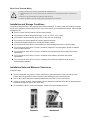
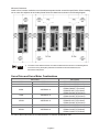
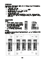
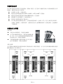
Minimum Clearances:
Install a fan to increase ventilation to avoid ambient temperatures that exceed the specification. When installing
two or more drive adjacent to each other please follow the clearances as shown in the following diagram.
NOTE
1) The scale of the clearances does not match the dimensions as shown in the drawing above.
In the event of any discrepancy between the clearances and the dimensions, the
dimensions shall prevail.
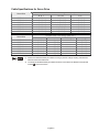
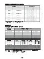
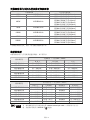
Servo Drive and Servo Motor Combinations
Servo Drive Servo Motor
100W ASD-B0121-A ECMA-C30401S (S=8mm)
200W ASD-B0221-A ECMA-C30602S (S=14mm)
400W ASD-B0421-A
ECMA-C30604S (S=14mm)
ECMA-C308047 (S=14mm)
ECMA-E31305S (S=22mm)
ECMA-G31303S (S=22mm)
750W ASD-B0721-A
ECMA-C30807S (S=19mm)
ECMA-G31306S (S=22mm)
1000W ASD-B1021-A
ECMA-C31010S (S=22mm)
ECMA-E31310S (S=22mm)
ECMA-G31309S (S=22mm)
1500W ASD-B1521-A ECMA-E31315S (S=22mm)
2000W ASD-B2023-A
ECMA-C31020S (S=22mm)
ECMA-C31320S (S=22mm)
ECMA-C31820S (S=35mm)
The boxes () in the model names are for optional configurations (shaft type and oil seal), and the last code at
the ends of the model names are for shaft dimension or customer identification code.

English-5
Cable Specifications for Servo Drive
Power Cable - Wire Gauge AWG (mm
2
)
Servo Drive
R, S, T U, V, W P, C
ASD-B0121-A 2.1 (AWG14) 0.82 (AWG18) 2.1 (AWG14)
ASD-B0221-A 2.1 (AWG14) 0.82 (AWG18) 2.1 (AWG14)
ASD-B0421-A 2.1 (AWG14) 0.82 (AWG18) 2.1 (AWG14)
ASD-B0721-A 2.1 (AWG14) 0.82 (AWG18) 2.1 (AWG14)
ASD-B1021-A 2.1 (AWG14) 3.3 (AWG12) 2.1 (AWG14)
ASD-B1521-A 2.1 (AWG14) 3.3 (AWG12) 2.1 (AWG14)
ASD-B2023-A 2.1 (AWG14) 3.3 (AWG12) 2.1 (AWG14)
Encoder Cable - Wire Gauge AWG (mm
2
)
Servo Drive
Wire Size Core Number UL Rating Wire Length
ASD-B0121-A 0.13 (AWG26) 10 core (4 pair) UL2464 3m (9.84ft.)
ASD-B0221-A 0.13 (AWG26) 10 core (4 pair) UL2464 3m (9.84ft.)
ASD-B0421-A 0.13 (AWG26) 10 core (4 pair) UL2464 3m (9.84ft.)
ASD-B0721-A 0.13 (AWG26) 10 core (4 pair) UL2464 3m (9.84ft.)
ASD-B1021-A 0.13 (AWG26) 10 core (4 pair) UL2464 3m (9.84ft.)
ASD-B1521-A 0.13 (AWG26) 10 core (4 pair) UL2464 3m (9.84ft.)
ASD-B2023-A 0.13 (AWG26) 10 core (4 pair) UL2464 3m (9.84ft.)
NOTE
1) Please use shielded twisted-pair cables for wiring to prevent voltage coupling and eliminate
electrical noise and interference.
2) The shield of shielded twisted-pair cables should be connected to the SHIELD end (terminal
marked ) of the servo drive.

English-6
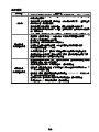
Basic Inspection
After power in connected to the AC servo drive, the charge LED will be lit which indicates that the AC servo
drive is ready.
Item Content
General Inspection
Periodically inspect the screws of the servo drive, motor shaft, terminal block and
the connection to mechanical system. Tighten screws as necessary as they may
loosen due to vibration and varying temperatures.
Ensure that oil, water, metallic particles or any foreign objects do not fall inside the
servo drive, motor, control panel or ventilation slots and holes. As these will cause
damage.
Ensure the correct installation and the control panel. It should be free from airborne
dust, harmful gases or liquids.
Ensure that all wiring instructions and recommendations are followed; otherwise
damage to the drive and or motor may result.
Inspection before
operation
(Control power is not
applied)
To avoid an electric shock, be sure to connect the ground terminal of servo drive to
the ground terminal of control panel.
Before making any connection, wait 10 minutes for capacitors to discharge after
the power is disconnected, alternatively, use an appropriate discharge device to
discharge.
Ensure that all wiring terminals are correctly insulated.
Ensure that all wiring is correct or damage and or malfunction may result.
Visually check to ensure that there are not any unused screws, metal strips, or any
conductive or inflammable materials inside the drive.
Never put inflammable objects on servo drive or close to the external regenerative
resistor.
Make sure control switch is OFF.
If the electromagnetic brake is being used, ensure that it is correctly wired.
If required, use an appropriate electrical filter to eliminate noise to the servo drive.
Ensure that the external applied voltage to the drive is correct and matched to the
controller.
Inspection during
operation
(Control power is
applied))
Ensure that the cables are not damaged, stressed excessively or loaded heavily.
When the motor is running, pay close attention on the connection of the cables and
notice that if they are damaged, frayed or over extended.
Check for abnormal vibrations and sounds during operation. If the servo motor is
vibrating or there are unusual noises while the motor is running, please contact the
dealer or manufacturer for assistance.
Ensure that all user-defined parameters are set correctly.
Reset parameters when the servo drive is off. Otherwise, it may result in
malfunction.
Ensure correct operation when using a relay and request assistance should there
be any unusual noises.
Check for abnormal conditions of the power indicators and LED display.

English-7
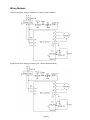
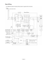
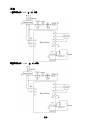
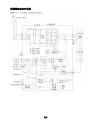
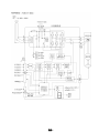
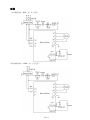
Wiring Methods
Three-Phase Power Supply Connection (For 2kW and above models)
Single-Phase Power Supply Connection (For 1.5kW and below models)

English-8
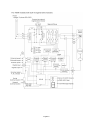
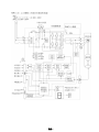
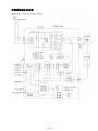
Basic Wiring

English-9

English-10

English-11
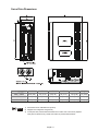
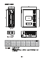
Servo Drive Dimensions
A B C D E Weight
100W ~ 400W 6.38 (162) 147 (5.79) 59 (2.32) 54 (2.13) 152 (5.98) 1.2 (2.64)
750W 6.38 (162) 147 (5.79) 79 (3.11) 62 (2.44) 152 (5.98) 1.5 (3.3)
1kW ~ 2kW 6.38 (162) 194 (7.64) 93 (3.66) 83 (3.27) 149 (5.87) 2.0 (4.4)
NOTE
1) Dimensions are in millimeters and (inches).
2) Weights are in kilograms and (pounds).
3) In this quick start, actual measured values are in metric units. The units in (imperial
units) are for reference only. Please use metric for precise measurements.

English-12
This page intentionally left blank.

繁中-1
序言
感謝您使用本產品,此份安裝手冊提供 ASDA-B 系列伺服驅動器及 ECMA 系列伺服馬達的相關資訊。在
使用之前,請您仔細詳讀本安裝手冊以確保使用上的正確。此外,請妥善將其放置在明顯的地點以便隨時
查閱。下列事項在您尚未讀完本安裝手冊前,請務必遵守:
安裝的環境必須沒有水氣,腐蝕性氣體及可燃性氣體。
接線時禁止將三相電源接至馬達 U、V、W 的接頭,一旦接錯時將損壞伺服驅動器。
接地工程必須確實實施,接地時須遵照國家現行相關電工法規之規定施行(請參考 NFPA 70:
National Electrical Code, 2005 Ed.)。
在通電時,請勿拆解驅動器、馬達或更改配線。
在通電運作前,請確定緊急停機裝置是否隨時啟動。
在通電運作時,請勿接觸散熱片,以免燙傷。
更多 ASDA-B 系列伺服驅動器及 ECMA 系列伺服馬達的相關資訊詳述於使用操作手冊內,您可至台達網
站(http://www.delta.com.tw/industrialautomation/
)下載使用操作手冊(pdf 檔)。
如果您在使用上仍有問題,請洽詢經銷商或者本公司客服中心。由於產品精益求精,當內容規格有所修正
時,請洽詢代理商或至台達網站(http://www.delta.com.tw/industrialautomation/
)下載最新版本。
安全注意事項
ASDA-B 系列為一開放型(Open Type)伺服驅動器,操作時須安裝於遮敝式的控制箱內。本驅動器利用
精密的回授控制及結合高速運算能力的數位信號處理器(Digital Signal Processor, DSP),控制 IGBT 產
生精確之電流輸出,用來驅動三相永磁式同步交流伺服馬達(PMSM)達到精準定位。
ASDA-B 系列可使用於工業應用場合上,且建議安裝於使用手冊中之配線(電)箱環境(驅動器、線材及馬
達都必須安裝於符合 UL50 Type 1 或者是 NEMA 250 Type 1 的安裝環境最低要求規格)。
接收檢驗、安裝、配線、操作、維護及檢查時,應隨時注意以下安全注意事項。
接收檢驗
¾ 請依照指定的方式搭配使用伺服馬達及伺服驅動器,否則可能會導致火災或設備故障。
安裝注意
¾ 禁止將本產品暴露在有水氣、腐蝕性氣體、可燃性氣體等物質的場所下使用,否則可
能會造成觸電或火災。
配線注意
¾ 請將接地端子連接到 class-3(100 Ω 以下)之接地,接地不良可能會造成觸電或火災。
¾ 請勿連接三相電源至 U、V、W 馬達輸出端子,否則可能會造成人員受傷或導致火災。
¾ 請鎖緊電源及馬達輸出端子的固定螺絲,否則可能造成火災。

繁中-2
操作注意
¾ 當機械設備開始運轉前,須配合其使用者參數調整設定值。若未調整到相符的正確設
定值,可能會導致機械設備運轉失去控制或發生故障。
¾ 機器開始運轉前,請確認是否可以隨時啟動緊急開關停機。
¾ 當馬達運轉時,禁止接觸任何旋轉中的馬達零件,否則可能會造成人員受傷。
¾ 為了避免意外事故,請先分開機械設備的連軸器及皮帶等,使其處於單獨的狀態,再
進行第一次試運轉。
¾ 在伺服馬達和機械設備連接運轉後,如果發生操作錯誤,則不僅會造成機械設備的損
壞,有時還可能導致人身傷害。
¾ 強烈建議:請先在無負載情況下,測試伺服馬達是否正常運作,之後再將負載接上,
以避免不必要的危險。
¾ 在運轉中請不要觸摸伺服驅動器之散熱器,否則可能會因高溫而發生燙傷。
保養及檢查
¾ 禁止接觸伺服驅動器及伺服馬達內部,否則可能會造成觸電。
¾ 電源啟動時,禁止拆下驅動器面板,否則可能會造成觸電。
¾ 電源關閉 10 分鐘內,不得接觸接線端子,殘餘電壓可能造成觸電。
¾ 不得拆開伺服馬達,否則可能會造成觸電或人員受傷。
¾ 不得在開啟電源情況下改變配線,否則可能造成觸電或人員受傷。
¾ 只有合格的電機專業人員才可以安裝、配線及修理保養伺服驅動器以及伺服馬達。
主電路配線
¾ 請不要將動力和小信號線從同一管道內穿過,也不要將其綁扎在一起。配線時,請使
動力線和信號相隔 30 公分(11.8 英吋)以上。
¾ 對於信號線、編碼器(PG)反饋線,請使用多股絞合線以及多蕊絞合整體屏蔽線。對
於配線長度,信號輸入線最長為 3 公尺(9.84 英呎),PG 反饋線最長為 20 公尺(65.62
英呎)。
¾ 即使關閉電源,伺服驅動器內部仍可能會滯留高電源,請暫時(10 分鐘)不要觸摸電
源端子。並請確認「CHARGE」指示燈熄滅後,再進行檢查作業。
¾ 請不要頻繁地開關電源。如果需要連續開關電源時,請控制在一分鐘一次以下。
主電路端子座配線
¾ 端子座的一個電線插入口,請僅插入一根電線。
¾ 在插入電線時,請不要使芯線與鄰近的電線短路。
¾ 芯線之線頭請使用 Y 接端子固定。
¾ 在上電之前,請確實檢查配線是否正確。

繁中-3
安裝環境條件
本產品在安裝之前必須置於其包裝箱內,若暫時不使用,為了使該產品能夠符合本公司的保固範圍及日後
的維護,儲存時務必注意下列事項:
必須置於無塵垢、乾燥之位置。
儲存位置的環境溫度必須在-20°C to +65°C(-4°F to 149°F)範圍內。
儲存位置的相對溼度必須在 0%到 90%範圍內,且無結露。
避免儲存於含有腐蝕性氣、液體之環境中。
最好適當包裝存放在架子或台面。
本產品適合的安裝環境包括有:無發高熱裝置之場所﹔無水滴、蒸氣、灰塵及油性灰塵之場所﹔
無腐蝕、易燃性之氣、液體之場所﹔無漂浮性的塵埃及金屬微粒之場所﹔堅固無振動、無電磁雜
訊干擾之場所。
安裝方向與空間
注意事項:
安裝方向必須依規定,否則會造成 故障原因。
為了使冷卻循環效果良好,安裝交流伺服驅動器
時,其上下左右與相鄰的物品和擋板(牆)必須保
持足夠的空間,否則會造成故障原因。
交流伺服驅動器在安裝時其吸排氣孔不可封
住,也不可傾倒放置,否則會造成故障原因。
安裝示意圖:
為了使散熱風扇能夠有比較低的風阻以有效排出熱量,請使用者遵守一台與多台交流伺服驅動器的安裝間
隔距離建議值(如下圖所示)。

繁中-4
伺服驅動器與馬達機種名稱對應參照表
伺服驅動器 對應的伺服馬達
100W ASD-B0121-A ECMA-C30401S (S=8mm)
200W ASD-B0221-A ECMA-C30602S (S=14mm)
400W ASD-B0421-A
ECMA-C30604S (S=14mm)
ECMA-C308047 (S=14mm)
ECMA-E31305S (S=22mm)
ECMA-G31303S (S=22mm)
750W ASD-B0721-A
ECMA-C30807S (S=19mm)
ECMA-G31306S (S=22mm)
1000W ASD-B1021-A
ECMA-C31010S (S=22mm)
ECMA-E31310S (S=22mm)
ECMA-G31309S (S=22mm)
1500W ASD-B1521-A ECMA-E31315S (S=22mm)
2000W ASD-B2023-A
ECMA-C31020S (S=22mm)
ECMA-C31320S (S=22mm)
ECMA-C31820S (S=35mm)
為軸徑和油封型式;最後一碼為軸徑規格或客戶碼
線材的選擇
本驅動器各端子與信號配線的建議線材,如下表所示:
電源配線 — 線徑mm²(AWG)
驅動器型號
R, S, T U, V, W P, C
ASD-B0121-A
2.1(AWG14) 0.82(AWG18) 2.1(AWG14)
ASD-B0221-A
2.1(AWG14) 0.82(AWG18) 2.1(AWG14)
ASD-B0421-A
2.1(AWG14) 0.82(AWG18) 2.1(AWG14)
ASD-B0721-A
2.1(AWG14) 0.82(AWG18) 2.1(AWG14)
ASD-B1021-A
2.1(AWG14) 3.3(AWG12) 2.1(AWG14)
ASD-B1521-A
2.1(AWG14) 3.3(AWG12) 2.1(AWG14)
ASD-B2023-A
2.1(AWG14) 3.3(AWG12) 2.1(AWG14)
編碼器配線 — 線徑mm²(AWG)
驅動器型號
芯線尺寸 芯線條數 線種規範 標準線長
ASD-B0121-A
0.13(AWG26) 10 條(4 對)
UL2464
3 公尺(9.84 英呎)
ASD-B0221-A
0.13(AWG26) 10 條(4 對)
UL2464
3 公尺(9.84 英呎)
ASD-B0421-A
0.13(AWG26) 10 條(4 對)
UL2464
3 公尺(9.84 英呎)
ASD-B0721-A
0.13(AWG26) 10 條(4 對)
UL2464
3 公尺(9.84 英呎)
ASD-B1021-A
0.13(AWG26) 10 條(4 對)
UL2464
3 公尺(9.84 英呎)
ASD-B1521-A
0.13(AWG26) 10 條(4 對)
UL2464
3 公尺(9.84 英呎)
ASD-B2023-A
0.13(AWG26) 10 條(4 對)
UL2464
3 公尺(9.84 英呎)
NOTE
1) 編碼器配線請使用雙絞隔離線((shielded twisted-pair cable),以減低雜訊的干擾。
2) 隔離網必須確實與 SHIELD 端
相連接。

繁中-5
基本檢測
檢測項目 檢測內容
一般檢測
定期檢查伺服驅動器安裝部、馬達軸心與機械連接處的螺絲、端子台與機械部
的螺絲是否有鬆動。
控制箱的間隙或通風扇設置,應避免油、水或金屬粉等異物侵入,且應防止電
鑽的切削粉落入伺服驅動器內。
控制箱設置於有害氣體或多粉塵的場所,應防止有害氣體與粉塵的侵入。
製作檢出器接線或其他接線時,必須謹慎注意接線順序,否則可能發生設備暴
衝、燒毀等狀況。
操作前檢測
(未供應控制電源)
為防止觸電,伺服驅動器的接地保護端子必須連接控制箱的接地保護端子。如
需配線時,請在電源切斷 10 分鐘後進行,或直接以放電裝置進行放電。
配線端子的接續部請實施絕緣處理。
配線應正確,避免造成損壞或發生異常動作。
檢查螺絲或金屬片等導電性物體、可燃性物體是否存在伺服驅動器內。
緊急停止開關是否置於 OFF 狀態。
為避免電磁制動器失效,請檢查立即停止運轉及切斷電源的迴路是否正常。
伺服驅動器附近使用的電子儀器受到電磁干擾時,請使用儀器降低電磁干擾。
請確定伺服驅動器的外加電壓準位是否正確。
運轉前檢測
(已供應控制電源)
檢出器電纜應避免承受過大應力。當馬達在運轉時,注意接續電纜是否與機件
接觸而產生磨耗,或發生拉扯現象。
伺服馬達若有振動現象,或運轉聲音過大,請與廠商聯絡。
確認各項參數設定是否正確,依機械特性的不同可能會有無法預期的動作。勿
將參數作過度極端之調整。
重新設定參數時,請確定驅動器是否在伺服停止(SERVO OFF)的狀態下進
行,否則會成為故障發生的原因。
繼電器動作時,若無接觸的聲音或其他異常聲音產生,請與廠商聯絡。
電源指示燈與 LED 顯示有異常現象,請與廠商聯絡。

繁中-6
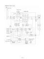
配線
三相電源接線法(2kW(含)以上適用)
單相電源接線法(1.5kW(含)以下適用)

繁中-7
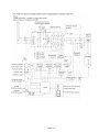
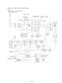
伺服系統基本方塊圖
ページが読み込まれています...
ページが読み込まれています...
ページが読み込まれています...
ページが読み込まれています...
ページが読み込まれています...
ページが読み込まれています...
ページが読み込まれています...
ページが読み込まれています...
ページが読み込まれています...
ページが読み込まれています...
ページが読み込まれています...
ページが読み込まれています...
ページが読み込まれています...
-
 1
1
-
 2
2
-
 3
3
-
 4
4
-
 5
5
-
 6
6
-
 7
7
-
 8
8
-
 9
9
-
 10
10
-
 11
11
-
 12
12
-
 13
13
-
 14
14
-
 15
15
-
 16
16
-
 17
17
-
 18
18
-
 19
19
-
 20
20
-
 21
21
-
 22
22
-
 23
23
-
 24
24
-
 25
25
-
 26
26
-
 27
27
-
 28
28
-
 29
29
-
 30
30
-
 31
31
-
 32
32
-
 33
33


Delta Electronics AC Servo Drive ASDA-B クイックスタートガイド
- タイプ
- クイックスタートガイド
他の言語で
その他のドキュメント
-
Mitsubishi Electric AC Servos 取扱説明書
-
-
Mitsubishi Electric MR-D01 EXTENSION IO UNIT インストールガイド
-
-
Yamaha S12 取扱説明書
-
-
-
-
-
CTEK SMARTPASS 120 取扱説明書