
© 2004 Sony Corporation
SU-PW2 4-099-792-42(1)
4-099-792-42 (1)
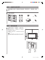
Wall-Mount Bracket
Instructions
SU-PW2
GB
CS
CT
KR
AR

SU-PW2 4-099-792-42(1)
2 (GB)
Plasma TV KE-MX37A1 KE-MX37S1 KE-MX37N1 KE-MX37K1
(Display Model)
KE-MX42A1 KE-MX42S1 KE-MX42N1 KE-MX42K1 KE-MX42M1
KE-42MR1 KE-42MR1E KE-50MR1 KE-P50MR1E KE-61MR1
(PDM-4200) (PDM-4200) (PDM-5000) (PDM-5000) (PDM-6100)
Thank you for purchasing this product.
To Customers
Sufficient expertise is required for installing this product. Be sure to subcontract the installation to Sony dealers
or contractors and pay special attention to safety during the installation. Sony is not liable for any damages or
injury caused by mishandling or improper installation.
WARNING
If the safety precautions are not observed or the product is used incorrectly, it may result in serious injury or fire.
This instruction manual shows the correct handling of the product and important precautions necessary to prevent
accidents. Be sure to read this manual thoroughly and use the product correctly. Keep this manual available for
future reference.
For Sony dealers
Sufficient expertise is required for installing this product. Be sure to read this instruction manual thoroughly to do
the installation work safely. Sony is not liable for any damages or injury caused by mishandling or improper
installation. Please give this manual to the customer after installation.
On Safety
Products by Sony are designed with safety in mind.
If the products are used incorrectly, however, it may result in a serious injury through fire, electric shock, the
product toppling over, or the product dropping. Be sure to observe the precautions for safety to prevent such
accidents.
CAUTION
This Wall-Mount Bracket is intended for use only with the following products. Use with other apparatus is capable
of resulting in instability causing possible injury.
Specified product (As of June 2004)

SU-PW2 4-099-792-42(1)
English
GB
3 (GB)
For Customers
WARNING
If the following precautions are not observed, serious injury or death through fire, electric shock, the
product toppling over, or the product dropping can result.
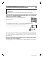
Be sure to subcontract the installation to qualified contractors and keep small
children away during the installation.
If the Wall-Mount Bracket or the Display Unit is not installed correctly, the
following accidents may occur. Be sure qualified contractors carry out
installation.
• The Display Unit may fall and cause a serious injury such as a bruise or a
fracture.
• If the wall on which the Wall-Mount Bracket is installed is unstable,
uneven, or not perpendicular to the floor, the unit may fall and cause
injury or property damage. The wall should be capable of supporting a
weight of at least four times the Display Unit weight. (See the Display
installing dimensions table on page 9 for the weight of each Display Unit.)
• If the installation of the Wall-Mount Bracket on the wall is not sufficiently
sturdy, the unit may fall and cause injury or property damage.
Be sure to subcontract moving or dismounting of the Display Unit to qualified
contractors.
If persons other than qualified contractors transport or dismount the Display Unit, it may fall and cause injury or
property damage. Be sure that two or more persons carry or dismount the Display Unit.
Do not spill liquid of any kind on the Display Unit.
If you allow the Display Unit to get wet, this may result in a fire or an electric shock.
Do not remove screws, etc., after mounting the Display Unit.
If you do so, the Display Unit may fall and cause injury or property damage.
Do not disassemble or make alterations to the parts of the Wall-Mount
Bracket.
If you do so, the Wall-Mount Bracket may fall and cause injury or property
damage.
Do not mount any equipment other than the specified product.
This Wall-Mount Bracket is designed for use with the specified product only. If you mount equipment other than
specified, it may fall or break, and cause injury or property damage.

SU-PW2 4-099-792-42(1)
4 (GB)
Do not cover the ventilation hole of the Display Unit.
If you cover the ventilation hole (with a cloth, etc.), heat may build up inside
and cause fire.
Do not apply any load other than the Display Unit on the Wall-Mount
Bracket.
If you do so, the Display Unit may fall and cause injury or property damage.
Do not lean on or hang from the Display Unit.
Do not lean on or hang from the Display Unit as it may fall on you
and cause serious injury.
Do not expose the Display Unit to rain or moisture.
It may cause a fire or an electric shock.
Never place the Display Unit in hot, humid or excessively dusty places, or in
the place where the unit is subjected to mechanical vibrations.
If you do so, it may cause a fire or an electric shock.
Keep flammable objects or open flames (e.g. candles) away from the Display
Unit.
To prevent a fire, keep flammable objects or open flames (e.g. candles) away from the Display Unit.

SU-PW2 4-099-792-42(1)
GB
5 (GB)
CAUTION
If the following precautions are not observed, injury or property damage may occur.
Do not install the Wall-Mount Bracket on wall surfaces where the corners or
the sides of the Display Unit protrude away from the wall surface.
Do not install the Wall-Mount Bracket on wall surfaces such as a pillar,
where the corners or the sides of the Display Unit protrude away from the
wall surface. If a person or object happens to hit the protruded corner or side
of the Display Unit, it may cause injury or property damage.
Do not handle the product with excessive force during cleaning or
maintenance.
Do not apply excessive force on the topside of the Display Unit. If you do so, the Display Unit may fall and cause
injury or property damage.
Do not install the Display Unit over or under an air-conditioner.
If the Display Unit is exposed to water leaks or air current from an air-conditioner for a long time, it may cause a
fire, an electric shock or a malfunction of the Display Unit.
Precautions
• If you use the Display Unit installed on the Wall-Mount Bracket for a long time, the wall behind or above the
Display Unit may become discoloured or the wallpaper may come unstuck, depending on the material of the
wall.
• If the Wall-Mount Bracket is removed after installing it on the wall, the screw holes are left.
• If you have routed 300-ohm feeder cables behind the wall, we recommend that you change them to 75-ohm
coaxial cables.
If it is necessary to continue to use 300-ohm feeder cables, be sure there is sufficient space available between the
Display Unit and the feeder cables behind the wall before installing. Consult your contractor regarding an
appropriate location (free from radio noise, etc.) before installing.

SU-PW2 4-099-792-42(1)
6 (GB)
Install the Wall-Mount Bracket
WARNING
To Sony Dealers
The following instructions are for Sony Dealers only. Be sure to read safety precautions described above and
pay special attention to safety during the installation, maintenance and checking of this product.
Be sure to install the Wall-Mount Bracket securely to the wall following the
instructions in this instruction manual.
If any of the screws are loose or fall out, the Wall-Mount Bracket may fall
and cause injury or property damage. Be sure to use the appropriate screws
for the material of the wall and install the unit securely, using four or more
M8 (or equivalent) screws.
Do not allow the mains lead or the connecting cable to be pinched.
If the mains lead or the connecting cable is pinched between the unit and the
wall or is bent or twisted by force, the internal conductors may become
exposed and cause a short circuit or an electrical break. This may cause a fire
or an electric shock.
Be sure to use the supplied screws and attachment parts properly following
the instructions given in this instruction manual. If you use substitute items,
the Display Unit may fall, and cause bodily injury to someone or damage to
the Display Unit.
Be sure to assemble the bracket properly following the instructed procedure
explained in this instruction manual.
If any of the screws are loose or fall out, the Display Unit may fall, and cause bodily injury to someone or damage
to the Display Unit.
For Sony Dealers

SU-PW2 4-099-792-42(1)
GB
7 (GB)
Be sure to tighten the screws securely in the designated position.
If you fail to do so, the Display Unit may fall, and cause bodily injury to someone or damage to the Display Unit.
Be careful not to subject the Display Unit to shock during installation.
If the Display Unit is exposed to shock, it may fall or break apart. This may cause injury.
Be sure to install the Display Unit on a wall that is both perpendicular and
flat.
If you fail to do so, the Display Unit may fall and cause injury.
After proper installation of the Display Unit, secure the cables properly.
If people or objects get tangled in the cables, this may result in injury or damage to the Display Unit.
Be careful not to hurt your hands or fingers during the installation.
Be careful not to hurt your hands or fingers when installing the Wall-Mount Bracket or the Display Unit.
The screws needed to secure the Wall-Mount Bracket to the wall are not
supplied.
Use the appropriate screws for the wall material and structure when mounting the Wall-Mount Bracket.

SU-PW2 4-099-792-42(1)
8 (GB)
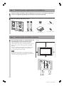
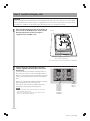
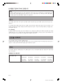
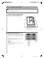
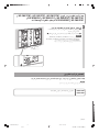
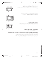
Step 2: Decide on the installation location
1
Unit: mm
300
100
100
100
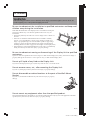
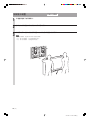
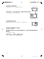
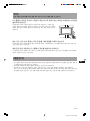
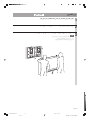
Place the paper template on a perpendicular, flat
wall and decide on the installation location.
Tape the supplied 3 sheets of the paper template
together with commercially available adhesive tape. For
details, refer to the instructions printed on the paper
template.
Allow for suitable clearance between the Display Unit
and the ceiling and protruding parts of the wall as
shown in the diagram on the right.
Note
If you intend to route the cables in a wall, make a hole in the wall
beforehand to make sure that the cables can be drawn into the wall.
The positions for the cable holes are printed on the paper template and
on page 10 according to the Display Unit model.
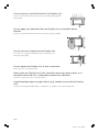
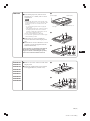
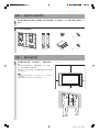
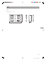
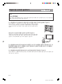
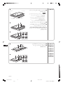
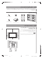
1
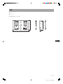
2
Plate Unit (1) Mounting Hook Unit (2)
Hook (4)
Paper Template
(1 set of 3 sheets)
Screw (+PSW5 × L16) (6)
Screw (+B6 × L20) (2)
Step 1: Check the parts required for the installation
Prepare a Phillips screwdriver and the appropriate screws (four or more M8 (or equivalent)
screws, not supplied), depending on the material of the wall, beforehand.
Open the package and check the parts.

SU-PW2 4-099-792-42(1)
GB
9 (GB)
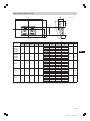
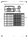
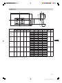
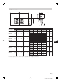
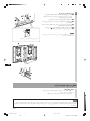
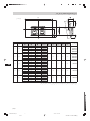
Display Dimensions Unit: mm Length for each mounting angle Unit: mm Weight
Display Model
ABCDE
Mounting
FGHWeight (× 4)*
angle (αº)
KE-MX37A1
0º 165 149 75
KE-MX37S1
5º 209 138 84
1135 617 110 246 75 10º 251 123 94 33 kg 132 kg
KE-MX37N1
15º 292 104 103
KE-MX37K1
20º 330 82 111
KE-MX42A1 0º 165 210 75
KE-MX42S1 5º 214 199 84
KE-MX42N1 1229 678 110 277 75 10º 262 183 94 38 kg 154 kg
KE-MX42K1 15º 307 163 103
KE-MX42M1 20º 351 139 111
0º 157 198 138
5º 204 179 147
PDM-4200 1352 720 102 224 138 10º 250 164 155 39 kg 156 kg
15º 294 146 162
20º 336 124 168
0º 163 324 139
1573 856 108 292 139
5º 222 312 149
PDM-5000 10º 279 296 157 53 kg 212 kg
15º 334 274 165
20º 387 249 171
0º 165 407 137
5º 230 395 147
PDM-6100 1797 937 110 335 137 10º 295 378 156 71 kg 284 kg
15º 358 355 164
20º 418 327 171
A
B
D
E
B
C
F
G
H
393 ± 0.5
* The wall that the Display Unit will be installed on should be capable of supporting a weight of at least four times that of the Display Unit.
Display installing dimensions table
Unit: mm

SU-PW2 4-099-792-42(1)
10 (GB)
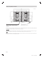
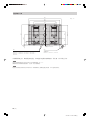
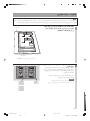
Referring to the paper template and the diagram above, determine the positions of the screws and the cable hole (if
you intend to route the cables in the wall), and work on the wall.
WARNING
The wall that the Display Unit will be installed on should be capable of supporting a weight of at least four times that of the Display Unit (page 9).
Make sure of the strength of the wall the Display Unit will be installed on. Reinforce the wall sufficiently, if necessary.
Note
The position of the cable hole varies depending on the Display Unit model. Determine the position of the cable hole using the paper template or
the diagram above and bore a hole in an appropriate position.
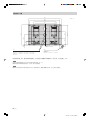
Wall processing dimensions diagram
Hole for cable routing:
PDM-4200 / PDM-5000 / PDM-6100
670
610
455
406
ø60
ø50
20 – 9 × 20
60
40 131
65.5
196.5
13.5
420
131
393 ± 0.5
Slot hole
Unit: mm
Hole for cable routing (One of two):
KE-MX37A1 / KE-MX37S1 / KE-MX37N1 / KE-MX37K1 /
KE-MX42A1 / KE-MX42S1 / KE-MX42N1 / KE-MX42K1 /
KE-MX42M1

SU-PW2 4-099-792-42(1)
GB
11 (GB)
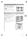
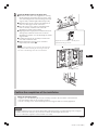
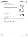
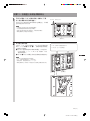
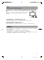
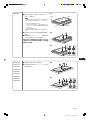
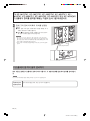
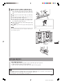
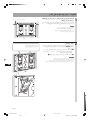
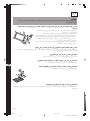
Adjust the angle of the arms.
When installing the Display Unit perpendicularly (0
degrees), adjustment of the arms angle (Procedure 1
and 2 below) is not necessary. Make sure that each arm
base is screwed in securely.
1 Remove the screws that are at the top and bottom
centre of the both arm bases. Then choose the notch
corresponding to the desired angle (5, 10, 15 or 20
degrees) and fit the arm base to it.
2 Firmly secure each arm base using the screws
removed in Procedure 1.
Notes
• Be sure to adjust the angles of the right and left arms to the same
angle.
• Be careful not to pinch your fingers when adjusting the angle of
arms.
• When using an electric screwdriver, set the torque setting to
approximately 2 N·m.
• Make sure that two Mounting Hook Unit support shaft on the lower
part of the Plate Unit are screwed in securely.
2
2
1
•0 degrees: Leave the white screws tightened as
they are.
• Other than 0 degrees: Remove the white screws.
Arm Base
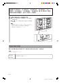
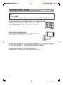
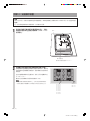
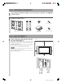
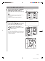
Step 3: Install the Plate Unit on the wall
1
Fix the Plate Unit to the wall using four or more
M8 (or equivalent) screws (not supplied).
Select at least four screw holes with the same mark
shown in the diagram on the right, and tighten the
screws securely so that they will not come loose.
WARNING
• The screws securing the Wall-Mount Bracket to the wall are not
supplied.
• Be sure to use the appropriate screws, depending on the material and
structure of the wall.
• If the Plate Unit cannot be attached securely enough, use additional
screws.
• Be sure to confirm that the Plate Unit is securely fixed to the wall.
Align the unit so that it is exactly level.
Plate Unit

SU-PW2 4-099-792-42(1)
12 (GB)
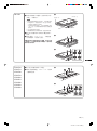
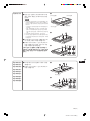
PDM-4200
PDM-5000
No preparations. Go to the next step.
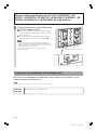
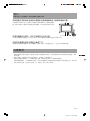
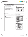
Prepare for the installation of the Display Unit
Preparation varies depending on the Display Unit to be installed. See the procedure for each
model and prepare for the installation.
Note
When using an electric screwdriver, set the torque setting to approximately 2 N·m.
Change the positions of the Mounting
Hook Unit support shafts.
1 Remove the screws from the left and right Mounting
Hook Unit support shafts and fit the support shafts in
the outer notches.
2 Firmly secure each Mounting Hook Unit support
shaft using the screws removed in Procedure 1.
Notes
• If you are installing a Display Unit other than KE-MX37A1, KE-
MX37S1, KE-MX37N1, KE-MX37K1, KE-MX42A1, KE-MX42S1, KE-
MX42N1, KE-MX42K1 or KE-MX42M1, do not change the position of
the Mounting Hook Unit support shafts.
• When using an electric screwdriver, set the torque setting to
approximately 2 N·m.
2
1
Mounting Hook Unit support shaft
When installing the Display Unit of the TV KE-MX37A1, KE-
MX37S1, KE-MX37N1, KE-MX37K1, KE-MX42A1, KE-MX42S1, KE-
MX42N1, KE-MX42K1 or KE-MX42M1, do step 3 below.
3

SU-PW2 4-099-792-42(1)
GB
13 (GB)
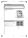
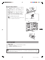
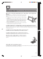
PDM-6100
1 Place the Display Unit, with its screen
facing down, on a stable, cloth-covered
work surface.
Notes
• If the weight of the Display Unit is placed on the
speakers, deformation or a loose connection of the
speakers may result. To avoid this, observe the
following.
– Do not hold the speakers when carrying the
Display Unit.
– Place packing material, etc. on the floor and lay
the Display Unit face down on it so that the
speakers on either side of the Display Unit are
clear of the packing material, etc.
• Be sure to place the Display Unit stably.
• Use soft cloth to protect the screen of the Display
Unit from damage or dirt.
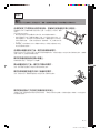
2 Remove the two screws and the two
hooks at the bottom of the Display Unit
rear.
3 Attach the two hooks with the two screws
(+PSW5 × L16) (both supplied with the
Wall Mount Bracket).
If you intend to use the Display Unit without
the speakers, detach the speakers at this
stage. For details on detaching the speakers,
refer to the instruction manual of the TV.
3
2
1
Packing material, etc.
Speaker (left)
Speaker (right)
Soft rag
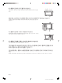
KE-MX37A1
KE-MX37S1
KE-MX37N1
KE-MX37K1
KE-MX42A1
KE-MX42S1
KE-MX42N1
KE-MX42K1
KE-MX42M1
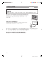
1 Remove six screws on the rear side of the
Display Unit.
2 Attach the supplied four hooks with the
four supplied screws (+PSW5 × L16).
1
Soft rag
2

SU-PW2 4-099-792-42(1)
14 (GB)
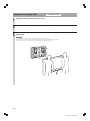
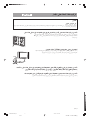
Connect the mains lead and the connecting
cable(s) supplied with the Display Unit to the
Display Unit.
Connect the mains lead and the connecting cable(s) to
the connectors on the rear side of the Display Unit. For
details on connecting the mains lead and the connecting
cable(s), refer to the instruction manual of the Display
Unit.
When you route the cable and the lead in the wall, feed
them through the hole you bored (page 10).
The position of the hole that should be bored varies
depending on the model of the Display Unit.
Notes
• Once you install the Display Unit to the Plate Unit, you cannot
connect the lead and the cables.
• Be sure to subcontract the routing of the cable in the wall and
electrical work to qualified contractors.
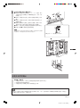
Step 4: Install the Display Unit
WARNING
Be sure to complete the installation before connecting the mains lead to the wall socket. If you allow the mains
lead to be pinched under or between pieces of equipment, this may result in a short circuit or an electric shock.
Be careful not to stumble over the mains lead or the Display Unit, as you may hurt yourself.
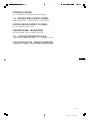
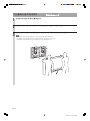
Hitch the Mounting Hook Unit on the hooks on
the rear side of the Display Unit. Then slide the
Mounting Hook Unit and fix it using the
supplied screws (+PSW5 × L16).
1
Rear side of the Display Unit
(The model of the Display Unit in the illustration is PDM-4200.)
Soft rag
2
PDM-4200
PDM-5000
PDM-6100
KE-MX37A1
KE-MX37S1
KE-MX37N1
KE-MX37K1
KE-MX42A1
KE-MX42S1
KE-MX42N1
KE-MX42K1
KE-MX42M1

SU-PW2 4-099-792-42(1)
GB
15 (GB)
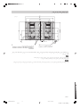
Install the Display Unit on the Plate Unit.
1 Insert the screws (+B6 × L20, supplied) for securing
the Mounting Hook Unit into the screw holes on the
outer left and right sides of the Mounting Hook Unit
support shafts, and then tighten them temporarily.
2 Hitch the upper hooks of the two Mounting Hook
Units on to the support shafts of the arms.
3 Place the lower hooks of the two Mounting Hook
Units so that they touch the front side of the
Mounting Hook Unit support shafts.
4 Slightly push the Display Unit toward the Plate Unit
and upward, to hitch the lower hooks of the two
Mounting Hook Units on to the Mounting Hook Unit
support shafts.
5 Confirm the eight hooks are firmly hooked on the
four shafts on the Plate Unit.
6 Firmly tighten the securing screws screwed in
temporarily in Procedure 1.
Note
If the temporarily attached screws for securing the Mounting Hook
Unit protrude inside the Mounting Hook Unit support shafts, the
lower hooks of the Mounting Hook Units cannot be fitted in.
3
1
2
3
4
6
Tighten the screws to halfway so that they do not
protrude from the opposite side.
Mounting Hook Unit
Confirm the completion of the installation
Check the following points.
• Eight hooks of the Mounting Hook Units are firmly hooked on the four shafts on the Plate Unit.
• The lead and the cable are not twisted or pinched.
• The two securing screws on the Mounting Hook Unit support shafts are securely tightened.
WARNING
Incomplete installation may cause the product falling and result in injury or product damage. Also, improper
placement of the mains lead, etc., may cause fire or electric shock through a short circuit.
Be sure to confirm the completion of the installation for safety.

SU-PW2 4-099-792-42(1)
16 (GB)
Remove the Display Unit
1
2
3
For Sony Dealers
Unplug the mains lead from the wall socket.
Remove the two securing screws on the right and left Mounting Hook Unit support shafts.
Be sure that two or more persons hold the Display Unit and slide it upward to remove the
Display Unit.
WARNING
• Be sure that two or more persons hold the Display Unit when carrying it.
• Be careful not to allow the leads and cables to get hung up when removing the Display Unit.
• Be careful not to hurt your hands or fingers when removing the Display Unit.

SU-PW2 4-099-792-42(1)
GB
17 (GB)
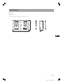
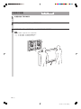
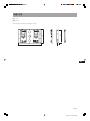
670
420
51
385
Specifications
Unit: mm
Weight: 9.0 kg
Design and specifications are subject to change without notice.

SU-PW2 4-099-792-42(1)
18 (GB)

SU-PW2 4-099-792-42(1)
Instructions
SU-PW2
GB
CS
CT
KR
AR

SU-PW2 4-099-792-42(1)
2 (CS)
ページが読み込まれています...
ページが読み込まれています...
ページが読み込まれています...
ページが読み込まれています...
ページが読み込まれています...
ページが読み込まれています...
ページが読み込まれています...
ページが読み込まれています...
ページが読み込まれています...
ページが読み込まれています...
ページが読み込まれています...
ページが読み込まれています...
ページが読み込まれています...
ページが読み込まれています...
ページが読み込まれています...
ページが読み込まれています...
ページが読み込まれています...
ページが読み込まれています...
ページが読み込まれています...
ページが読み込まれています...
ページが読み込まれています...
ページが読み込まれています...
ページが読み込まれています...
ページが読み込まれています...
ページが読み込まれています...
ページが読み込まれています...
ページが読み込まれています...
ページが読み込まれています...
ページが読み込まれています...
ページが読み込まれています...
ページが読み込まれています...
ページが読み込まれています...
ページが読み込まれています...
ページが読み込まれています...
ページが読み込まれています...
ページが読み込まれています...
ページが読み込まれています...
ページが読み込まれています...
ページが読み込まれています...
ページが読み込まれています...
ページが読み込まれています...
ページが読み込まれています...
ページが読み込まれています...
ページが読み込まれています...
ページが読み込まれています...
ページが読み込まれています...
ページが読み込まれています...
ページが読み込まれています...
ページが読み込まれています...
ページが読み込まれています...
ページが読み込まれています...
ページが読み込まれています...
ページが読み込まれています...
ページが読み込まれています...
ページが読み込まれています...
ページが読み込まれています...
ページが読み込まれています...
ページが読み込まれています...
ページが読み込まれています...
ページが読み込まれています...
ページが読み込まれています...
ページが読み込まれています...
ページが読み込まれています...
ページが読み込まれています...
-
 1
1
-
 2
2
-
 3
3
-
 4
4
-
 5
5
-
 6
6
-
 7
7
-
 8
8
-
 9
9
-
 10
10
-
 11
11
-
 12
12
-
 13
13
-
 14
14
-
 15
15
-
 16
16
-
 17
17
-
 18
18
-
 19
19
-
 20
20
-
 21
21
-
 22
22
-
 23
23
-
 24
24
-
 25
25
-
 26
26
-
 27
27
-
 28
28
-
 29
29
-
 30
30
-
 31
31
-
 32
32
-
 33
33
-
 34
34
-
 35
35
-
 36
36
-
 37
37
-
 38
38
-
 39
39
-
 40
40
-
 41
41
-
 42
42
-
 43
43
-
 44
44
-
 45
45
-
 46
46
-
 47
47
-
 48
48
-
 49
49
-
 50
50
-
 51
51
-
 52
52
-
 53
53
-
 54
54
-
 55
55
-
 56
56
-
 57
57
-
 58
58
-
 59
59
-
 60
60
-
 61
61
-
 62
62
-
 63
63
-
 64
64
-
 65
65
-
 66
66
-
 67
67
-
 68
68
-
 69
69
-
 70
70
-
 71
71
-
 72
72
-
 73
73
-
 74
74
-
 75
75
-
 76
76
-
 77
77
-
 78
78
-
 79
79
-
 80
80
-
 81
81
-
 82
82
-
 83
83
-
 84
84


