
Installation Instruction WT-T
Danfoss Heating Solutions VICUL12P 1
Installation Steps
1. Installation must be done by an authorized electrician!
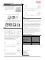
2. The room thermostat should be installed
at approx. 1.5m above floor and where
the effects of sunlight, draught or other
heat sources (eg. TV’s) are avoided
(Fig.1).
Fig.1
3. First of all, carefully remove the cover and dial knob (Fig.2).
Fig.2
4. Connect the wire before mounting the back plate to the wall box using
the enclosed screws. Then mount the cover to the back plate
(Fig.3).
Fig.3
Wiring
1. Dimension (Fig.4) and wiring diagram (Fig.5):
Fig.4 Fig.5
2. WT-T is often used with Danfoss TWA actuator. Depending on the
conditions of power location and actuator type (NC or NO), the wiring
between room thermostat and actuator is different. Follow the
illustrations below to complete the wiring:
1)When power supply location is close to room thermostat
i. Connect to actuator TWA 230V NC type (Fig.6)
Fig.6
ii. Connect to actuator TWA 230V NO type (Fig.7)
Fig.7
2) When power supply location is close to actuator
i. Connect to actuator TWA 230V NC type (Fig.8)
Fig.8
ii. Connect to actuator TWA 230V NO type (Fig.9)
Fig.9
Notes
1. Correct wiring is essential; using instrument to confirm L and N before
wiring is recommended.
2. Don’t remove too much of the insulation cover from the wire to avoid short
circuit caused by the naked wire touching the metal 86 size mounting wall
box.
3. Don’t let the screw press or touch the wire when using screw to fix room
thermostat in wall box. A short circuit risk exists if the wire insulation cover
is damaged by the screw, and if the naked wire connects with the screw.
4. If walls must be painted, mount the room thermostat after painting, to
avoid dust or paint material penetrating the room thermostat and thus
damaging the PCB.
5. The max load of relay is 3A (resistive) or 1A (inductive, such as pump,
motor). The relay will be damaged if the load exceeds the limit.
6. Don’t cover the thermostat, for instance by hanging towels directly in front
of it.
7. The room thermostat should be connected to the corresponding loop
actuator in individual room temperature control.
Technical Specification
Feature
Description
Approval
CE Marking
,
EN60730
Ambient temperature
-10℃-60℃
IP class
30
Max load,inductive
<1A
Max load
,
resistive
<3A
Power consumption
7W
Power supply
230Vac±10%
,
50/60Hz
Room temperature set range
5℃-30℃
Shell material
ABS+PC
Danfoss A/S Heating Solutions
Ulvehavevej 61
DK-7100 Vejle
Tel: +45 7488 8500
Fax: +45 7488 8501
www.heating.danfoss.com

安装指南
WT-T
Danfoss Heating Solutions VICUL12P 2
安装步骤
1.
安装必须由专业的电工进行操作!
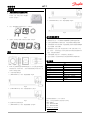
2. 温控器安装高度应距地面约 1.5m,避 免
如日照,气流,或其它热源(如电视机)
的影响(见 Fig.1)。
Fig.1
3. 首先,将控制器的前盖如图所示打开(见 Fig.2)。
Fig.2
4. 先接线,然后固定后背板,最后按上前盖板(见 Fig.3)。
Fig.3
接线
1. 外形尺寸(见 Fig.4)及接线端子(Fig.5):
Fig.4 Fig.5
2. WT-T常与丹佛斯热电驱动器 TWA 配套使用,由于电源位置及热电驱动
器的类型不同(常开和常闭),因此不同情况的接线方式略有不同,请
按照以下说明进行接线:
1)当电源在温控器旁边时
i. 与 TWA 230V NC 型(常闭)相连的接线图(Fig.6)
Fig.6
ii. 与 TWA 230V NO 型(常开)相连的接线图(见 Fig.7)
Fig.7
2) 当电源在热电驱动器旁边时
i. 与 TWA 230V NC 型(常闭)相连的接线图(见 Fig.8)
Fig.8
ii. 与 TWA 230V NO 型(常开)相连的接线图(Fig.9)
Fig.9
其它安装注意事项
1. 必须保证接线正确,接线前应用万用表和电笔检查明确 L 和 N线。
2. 接线剥皮不易过长,以免裸露部分相接触或触及金属 86 盒造成短路。
3. 注意固定温控器的螺栓不要挤压电线,以免电线破裂与螺栓造成短路。
4. 宜在墙面装修后再安装温控器,以避免装修粉尘或涂料从温控器顶部缝隙
中进入温控器,损坏电路板。
5. 温控器控制开关电流为 3A(纯电阻负载时)和 1A(感性负载时,如电
机,水泵等),禁止将超过开关允许电流的大功率负载直接与温控器开关
相接,否则会烧毁电路板。
6. 不要在温控器上覆盖东西,比如直接在它上面悬挂毛巾。
7. 进行分室温控时,温控器所在房间与热电驱动器所在的回路要相对应。
技术参数
特点 描述
认证
CE
认证,
EN60730
环境温度
-10
℃
-60
℃
IP
等级
30
最大电流,感性负载
<1A
最大电流,阻性负载
<3A
功耗
7W
电源
230Vac±10%
,
50/60Hz
温度设定范围
5
℃
-30
℃
外壳材料
ABS+PC
丹佛斯自动控制管理(上海)有限公司
地址:上海市宜山路 900号科技大厦 C 座 20 层
邮编:200233
电话:+86 21 61513000
传真:+86 21 61513100
www.danfoss.com/china
cn.heating.danfoss
-
 1
1
-
 2
2


他の言語で
- English: Danfoss WT-T Installation guide
関連論文
-
Danfoss WT-D_P インストールガイド
-
-
-
-
Danfoss GreenCon RC-C2/C4 room thermostat インストールガイド
-
-
Danfoss TWA-Q 取扱説明書
-
-
Danfoss Oil Burner Controls BHO 70 series インストールガイド