Johnson Controls T7000 Series Installation Instructions Manual
- タイプ
- Installation Instructions Manual

T7000 LCD Digital Thermostat
Installation Instructions
T7600-TF21-...JS0, T7601-TF20-...JS0, T7600-TF20-...JS0, T7603-T000-...JF0,
T7600-TB21-...JA0
Refer to the QuickLIT website for the most up-to-date version of this document
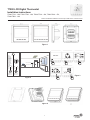
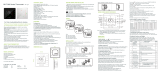
Figure 1
Figure 4
1
Figure 2
Figure 3
℃
/
o
F
AUTO
> 50 cm (19.68 inch)
> 150 cm (59.05 inch)
°C
•
•
Ambient
• Ambiante
• Umgebung
• Ambiente
• Ambiente
• Atmosfeer
• Omgivnin
• Prostředí
• Otoczenia
• Среда
• Omgivelse
MAX MIN MAX MIN
45 °C
113 °F
-0 °C
-32 °F
60 °C
140 °F
-10 °C
-14 °F
MAX 90% RH
MIN 10% RH
MAX 90% RH
MIN 10% RH
室温
ON / OFF
M
TiO2/ESP
Timer
Symbol
ON
ON
OFF
OFF

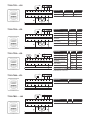
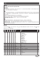
T7603-T000-...JF0
T7600-TB21-…JA0
Application VAL
Floor heater Floor heater water valve
Application AO AI
2-pipe FCU, AO valve Valve Actuator feedback
GND B AGND NTC OCC COM
LVAL N
T7601-TF20-...JS0
Application AO1 VAL2 VAL1
2-pipe relay valve
N/A
N/A Valve
4-pipe relay valve Heating Cooling
2-pipe 3-wire relay valve Valve off Valve on
2-pipe relay valve with
TiO2/ESP
TiO2/ESP Valve
2-pipe relay valve with
oor heating
Floor
heating
Valve
Water source heat pump Reversing Compressor
2-pipe AO valve Valve N/A N/A
Notes: F-ON is line voltage relay output, used for enable/
disable ECM fan in some case
FAN AO1
F-ON VAL2 VAL1
GND B AGND NTC OCC COM
L N
T7600-TF21-...JS0
Application AO2 AO1
2-pipe FCU N/A Valve
4-pipe FCU Heating Cooling
AO2GND B AAO1 GND NTC OCC COM
L HI MED LOW N
AIGND B AAO GND NTC OCC COM
L HI MED LOW N
T7600-TF20-...JS0
Application VAL2 VAL1
2-pipe relay valve N/A Valve
4-pipe relay valve Heating Cooling
2-pipe 3-wire relay valve Valve off Valve on
2-pipe relay valve with
TiO2/ESP
TiO2/ESP Valve
2-pipe relay valve with
oor heating
Floor heating Valve
Water source heat pump Reversing Compressor
GND B AGND NTC OCC COM
L HI MEDVAL2VAL1 LOW N

3
T7000
INSTALLATION INSTRUCTIONS FOR THE TECHNICIAN/FITTER
READ THIS INSTRUCTION SHEET AND THE SAFETY WARNING CAREFULLY BEFORE INSTALLING AND
SAVE IT FOR FUTURE USE
REPAIR AND REPLACEMENT
Do not attempt to repair the T7000 thermostat. In case of improperly functioning control, contact the nearest Johnson Controls®
representative, and specify the desired product code number. When con-tacting the supplier for a replacement please state the
type/model number of the control located on the data plate or cover label.
IMPORTANT:
• Use this T7000 thermostat only as an operating control. Where failure of malfunction of the T7000 thermostat could lead to
personal injury or property damage to the controlled equipment or other property, additional precautions must be designed into the
system. Incorporate and maintain other devices such as supervisory or alarm systems or safety or limit controls intended to warn
of, or protect against, failure or malfunction of the T7000 thermostat.
• Do not install this thermostat in condensing, wet, or damp environment. Moisture may cause damage to the thermostat.
• Do not remove PCB from the enclosure cover. Removing the PCB from the enclosure cover voids the product warranty.
• Make all wiring connection in accordance with local, nation, and regional regulations. Do not exceed the T7000 thermostat
electrical ratings.
• Remove LCD plastic cover before use
WARNING:
Disconnect power supply before making electrical connections. Contact with components carrying hazardous voltages can cause
electrical shock and may result in severe personal injury or death.
• Risk of Electrical Shock: Ground the thermostat according to local, national, and regional regulations. Failure to ground the
thermostat may result in electrical shock and severe personal injury and death.
• Risk of Electrical Shock and Property Damage: Insulate and secure each unused wire lead before applying power to the
thermostat. Failure to insulate and secure each unused wire lead may result property damage, electrical shock, and severe
personal injury or death.
Setup and adjustment:
Press and button for 5 seconds at power off mode (only press button for T7603-T000-...JF0), to get in parameter list, press
M button (press
button for T7603-T000-...JF0 ) to switch over setting items and use and button to change parameter
value.
Item
T7600-
TF21-
...JS0
T7601-
TF20-
...JS0
T7600-
TF20-
...JS0
T7603-
T000-
...JF0
T7600-
TB21-
...JA0
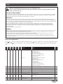
Parameter Function Default
01 ■ ■ ■ Application
T7601-TF20-...JS0 with EC Motor control
00: 2-pipe relay valve;
01: 4-pipe relay valve;
02: 2-pipe 3-wire relay valve;
03: 2-pipe relay valve with TiO2/ESP;
04: 2-pipe relay valve with oor heating;
05: water source heat pump;
06: 2-pipe AO valve
T7600-TF21-...JS0 Proportional Control
00: 2-pipe AO valve;
01: 4-pipe AO valve
T7600-TF20-...JS0 ON/OFF control
00: 2-pipe relay valve;
01: 4-pipe relay valve;
02: 2-pipe 3-wire relay valve;
03: 2-pipe relay valve with TiO2/ESP;
04: 2-pipe relay valve with oor heating;
05: water source heat pump
00
02 ■ ■ ■ ■ ■ Upper set point limit Setting range 2~40
℃
(36~99
o
F) 35
℃
03 ■ ■ ■ ■ ■ Lower set point limit Setting range 0~38
℃
(32~95
o
F) 5
℃
04 ■ ■ ■ ■ Cooling set point unoccupied Setting range 22~32
℃
(72~90
o
F) 26
℃
05 ■ ■ ■ ■ ■
Heating set point unoccupied Setting range 10~21℃ (50~70
o
F
) 18℃
06 ■ ■ ■ ■ ■
Frost protection 00: on; 01: off 00
07 ■ ■ ■ ■ ■
Frost protection set point Setting range 0~20℃ 5℃
08 ■ ■ ■ ■
Fan mode when set point
reach
00: off 01: low 00
09 ■ ■ ■ ■
Fan mode when unoccupied 00: low speed; 01: set speed 00
10 ■
ECM Min voltage Min voltage below which the fan output is 0%, range 0-10V. (0.5V) 3V

04: lock the keys except on/off
4
T7000
Item
T7600-
TF21-
...JS0
T7601-
TF20-
...JS0
T7600-
TF20-
...JS0
T7603-
T000-
...JF0
T7600-
TB21-
...JA0
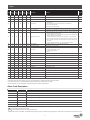
Parameter Function Default
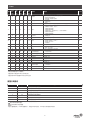
11 ■
ECM Max voltage Max voltage above which the fan output is 100%, range 0-10V. 10V
12 ■
ECM cut off relay 00: Disabled; 01: Enabled 00
13 ■ ■ ■ ■ ■
Restart after power failure 00: keep last status; 01: on; 02: off 00
14 ■ ■ ■ ■ ■
Keypad lock
00: no lock;
01: lock all keys;
02: lock the keys except fan speed and temp. adjustment;
03: lock on/off and general;
00
15 ■ ■ ■ ■ ■
Default display 00: display room temp.; 01: display set point only 00
16 ■ ■ ■ ■
Auto changeover 00: disable; 01: enable (When 2 pipe requires 10K NTC on water tube) 00
17 ■ ■ ■ ■ ■
Digital input function
00: open indicates key card is inserted (occupied), closed indicates key
card is pulled out (unoccupied);
01: closed indicates key card is inserted (occupied), open indicates key
card is pulled out (unoccupied);
02: closed indicates dew point risk, open indicates no dew point risk;
03: open indicates dew point risk, closed indi-cates no dew point risk;
04: open indicates occupied, closed indicates unoccupied, shut off fan
and valve;
05: closed indicates filter alarm; 06: open indicates filter alarm
00
18 ■ ■ ■ ■ ■
Unit selection 00: Celsius degree (℃); 01: Fahrenheit degree (
o
F
) 00
19 ■ ■ ■ ■ ■
Temperature offset Setting range –5~5℃(-9~9
o
F
) 0
20 ■ ■ ■ ■
Fan speed
00: 3 speed;
01: 2 speed (wiring MED, LOW);
02: 1 speed (wiring LOW);
03: no fan
00
21 ■ ■ ■ ■ ■
Language 00: Chinese; 01: English 00
22 ■ ■ ■ ■
Mode selection 00: cooling/heating/ventilation; 01: cooling only; 02: heating 00
23 ■ ■ ■ ■ ■
Back light The back light will be OFF in 05 ... 60 Sec 30
25 ■ ■ ■ ■ ■
Remote sensor type 00: China market 10KNTC; 01: JCI type II 10kNTC 00
26 ■ ■ ■ ■ ■
MODBUS address 1-64 1
27 ■ ■ ■ ■ ■
Baud rate 00: 9600; 01: 4800 00
28 ■ ■ ■
Sample time Setting range 1~99s 10
29 ■ ■ ■ ■ ■
Deadband Setting range 0~10℃ 1
30 ■ ■ ■
KP Setting range 1~99 10
31 ■ ■ ■
KI Setting range 0~99 01
32 ■ ■
TiO2/ESP operation 00: operate separately (corresponding button); 01: work with FCU fan 00
33 ■ ■
Inter stage difference Setting range 0~10℃ 3
34 ■ ■
Heating stage 00: 2 stage; 01: 1 stage 00
• Terminal blocks represent the most common application. Please check the application table first
•
The r
elay output are line voltage, they are connected with line voltage internally inside thermostat
•
The OC
C terminal can assume different meaning depending on parameter 17 setting
• The functionality of the remote NTC is depending by P25 and P16 parameters
Alarm Code Description
Item Code Description
1 E1 Internal sensor shorted warning
2 E2 Internal sensor opened warning
3 HI High temperature warning. Room Temperature > 55℃
4 LO Low temperature warning. Room Temperature < 0℃
5 E3 Remote sensor shorted
6 E4 Remote sensor opened
7 E5 Dew point risk warning
· E3,E4 only available for 2-pipe, auto mode enabled.
·
icon will twinkle if there is filter alarm
·
COM
symbol will ash if there are communication fault
· If the remote sensor is enabled, the E1/E2 warning will be ignored. If E1/E2 warning happened, T7000 will shut off the fan and close the valve.

5
T7000
安装指导
请在安装前仔细阅读该安装指导和安全警告维修和替换
维修和替换:
不要试图现场维修T7000系列温控器。如果T7000不能正常工作,请与附近江森自控办事处联系。当联系办事处更换产品的时
候,请说明外部标签或参数表上印有的类型/型号。
重要:
• T7000系列温控器仅用作设备控制。当T7000系列温控器调节装置失灵或故障时可能会导致人员伤害,财产损失及其他配备
损坏。请增加预防措施,如常使用监控及报警系统、电压保护开关等,在安装系统中。来加强此温度调节装置的机能失常和
失效时的保护。
• 不要把T7000装在结露、潮湿或有湿气处。湿气会损坏温控器。
• 不要把封入前盖的PCB板移出,从前盖中把封入的PCB板拆卸移出将不再享有质保服务。
• 使所有接线符合国家、地区和当地的规定。不要超过T7000系列温控器电流容量。
• 使用前请移除LCD塑料保护壳。
警告:
在进行电器接线时确保电源断开。在带电时连接各部件可能引起电击,从而导致人员受伤甚至死亡。
• 电击危险:按照国家、地区和当地的规定给温控器接地。接地失效可能导致电击和人员伤亡甚至死亡。
• 电击危险和财物损失:在温控器通电前把未使用的线头保护好,使之绝缘。任何一个未使用的线头未被绝缘和保护可能导致
财产损坏,电击和人员伤亡甚至死亡。
参数设定
关机状态下同时按 和 键(T7603-T000-...JF0按 键)5秒进入参数设定列表,按
M
键(T7603-T000-...JF0按
键)切换
参数设定项,按
/
键修改参数。
编号
T7600-
TF21-
...JS0
T7601-
TF20-
...JS0
T7600-
TF20-
...JS0
T7603-
T000-
...JF0
T7600-
TB21-
...JA0
参数项 功能含义 默认值
01
■ ■ ■
应用
T7601-TF20-...JS0
00:2管制开关阀;
01:4管制开关阀;
02:2管制3线开关阀;
03:2管制开关阀带TiO2/ESP;
04:2管制开关阀带地暖;
05:水源热泵;
06:2管制调节阀
T7600-TF21-...JS0
00:2管制调节阀;
01:4管制调节阀
T7600-TF20-...JS0
00:2管制开关阀;
01:4管制开关阀;
02:2管制3线开关阀;
03:2管制开关阀带TiO2/ESP;
04:2管制开关阀带地暖;
05:水源热泵
00
02
■ ■ ■ ■ ■
设定值上限 设定范围2~40℃ (36~99
o
F) 35℃
03
■ ■ ■ ■ ■
设定值下限 设定范围0~38℃ (32~95
o
F) 5℃
04
■ ■ ■ ■
无人状态制冷设定值 设定范围22~32℃ (72~90
o
F) 26℃
05
■ ■ ■ ■ ■
无人状态制热设定值 设定范围10~21℃ (50~70
o
F) 18℃
06
■ ■ ■ ■ ■
低温保护 00:开启;01:关闭 00
07
■ ■ ■ ■ ■
低温保护设定值 设定范围0~20℃ 5℃
08
■ ■ ■ ■
死区风机状态 00:关闭;01:低风速 00
09
■ ■ ■ ■
无人模式风机状态 00:低风速;01:用户设定风速 00
10
■
ECM风机电压输入下限 0%对应电压值,设定范围0-10V.(0.5V阶跃) 3V
11
■
ECM风机电压输入上限 100%对应电压值,设定范围0-10V.(0.5V阶跃) 10V
12
■
ECM风机继电器启停
00:禁用;
01:启用
00
13
■ ■ ■ ■ ■
掉电重启
00:恢复掉电前状态;
01:开启;
02:关闭
00

6
T7000
报警代码描述
编号 代码 描述
1 E1 内置温度传感器短路报警
2 E2 内置温度传感器开路报警
3 HI 高温报警,室内温度> 55℃
4 LO 低温报警,室内温度< 0℃
5 E3 外置温度传感器短路报警
6 E4 外置温度传感器开路报警
7 E5 露点传感器报警
· E3和E4报警仅在两管制风盘工作在自动切换模式时有效
·
图标闪烁表示滤网报警
·
COM
图标闪烁表示通讯报警
· 连接外置传感器时,E1和E2报警失效。当发生E1或E2报警,T7000会关闭风速及水阀输出
编号
T7600-
TF21-
...JS0
T7601-
TF20-
...JS0
T7600-
TF20-
...JS0
T7603-
T000-
...JF0
T7600-
TB21-
...JA0
参数项 功能含义 默认值
14
■ ■ ■ ■ ■
按键锁
00:禁用;01:锁定所有按键;
02:除风速及温度调节按键,锁定其他按键;
03:锁定开关及通用按键;
04:除开关键,锁定其他按键
00
15
■ ■ ■ ■ ■
默认显示
00:室内温度;
01:温度设定值
00
16
■ ■ ■ ■
自动模式
00:禁用;
01:启用(2管制FCU需要在水管安装10K NTC传感器)
00
17
■ ■ ■ ■ ■
BI输入
00:开路表示门卡插入(有人);
01:短路表示门卡插入(有人);
02:短路表示露点报警;
03:开路表示露点报警;
04:开路表示有人,短路表示无人,关闭风扇和阀门;
05:短路表示滤网报警;
06:开路表示滤网报警
00
18
■ ■ ■ ■ ■
温度单位
00:摄氏度(℃);
01:华氏度(
o
F)
00
19
■ ■ ■ ■ ■
温度偏移 设定范围–5~5℃(-9~9
o
F) 0
20
■ ■ ■ ■
风速
00:三风速;
01:两风速(接MED,LOW);
02:单风速(接LOW);
03:风扇禁用
00
21
■ ■ ■ ■ ■
语言 00:中文;01:英文 00
22
■ ■ ■ ■
模式
00:制冷/制热/通风;
01:单冷;02:单热
00
23
■ ■ ■ ■ ■
背光 05~60s,xx秒无操作,背光熄灭 30
25
■ ■ ■ ■ ■
外置传感器类型
00:中国版 10KNTC;
01:JCI版10kNTC
00
26
■ ■ ■ ■ ■
MODBUS地址 1-64 1
27
■ ■ ■ ■ ■
波特率 00:9600;01:4800 00
28
■ ■ ■
采样时间 设定范围1~99s 10
29
■ ■ ■ ■ ■
死区范围 设定范围0~10℃ 1
30
■ ■ ■
KP 设定范围1~99 10
31
■ ■ ■
KI 设定范围0~99 01
32
■ ■
TiO2/ESP操作
00:单独操作(通用键);
01:与风机联动
00
33
■ ■
制热阶段切换阈值 设定范围0~10℃ 3
34
■ ■
制热阶段 00:两级制热;01:单级制热 00
· 接线前请查看右侧应用表以确定端子接线方式
· 温控器内部继电器与火线相连
· 设置参数17可配置OCC端子为不同应用
· 设置参数16和25可配置NTC端子为不同应用

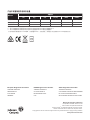
产品中有害物质的名称及含量
部件名称
有害物质
铅
(Pb)
汞
(Hg)
镉
(Cd)
六价铬
(Cr (VI))
多溴联苯
(PBB)
多溴二苯醚
(PBDE)
塑胶部件 O O O O O O
电路板及组件 X O O O O O
金属部件 O O O O O O
本表格依据SJ/T11364的规定编制
○ :表示该有害物质在该部件所有均质材料中的含量均在GB/T26572规定的限量要求以下
× :表示该有害物质在该部件所有均质材料中的含量超出GB/T26572规定的限量要求
(产品中使用的物料超出SJ/T11364标准,但在欧盟RoHS中,此项为豁免,因目前技术无法有符合SJ/T11364的替代材料)
European Single Point of Contact:
JOHNSON CONTROLS
WESTENDHOF 3
45143 ESSEN
GERMANY
NA/SA Single Point of Contact:
JOHNSON CONTROLS
507 E MICHIGAN ST
MILWAUKEE WI 53202
USA
APAC Single Point of Contact:
JOHNSON CONTROLS
C/O CONTROLS PRODUCT MANAGEMENT
NO. 22 BLOCK D NEW DISTRICT
WUXI JIANGSU PROVINCE 214142-CHINA
Building Technologies & Solutions
Headquarters: Milwaukee, Wisconsin, USA
Branch Officies: Principal Cities World-wide
Johnson Controls
®
are registered trademarks of Johnson Controls.
All other marks herein are the marks of their respective owners.
© Copyright 2017 Johnson Controls. All rights reserved. Any unauthorized use or copying is strictly prohibited.
www.johnsoncontrols.com
-
 1
1
-
 2
2
-
 3
3
-
 4
4
-
 5
5
-
 6
6
-
 7
7


Johnson Controls T7000 Series Installation Instructions Manual
- タイプ
- Installation Instructions Manual
他の言語で
- English: Johnson Controls T7000 Series
関連論文
その他のドキュメント
-
Samsung WA17M8100GV ユーザーマニュアル
-
 Sunsky BHT-006 Series ユーザーマニュアル
-
EXPERT4HOUSE BHT-006 Series ユーザーマニュアル
-
BECA BAC-1000 Series WiFi Thermostat ユーザーガイド
-
Delta Mini Relay IO Card ユーザーガイド
-
Bernard Controls AQ Range LOGIC Installation & Operation Manual
-
BECA BHT-8000 ユーザーガイド
-
Danfoss WT-D_P インストールガイド
-
-
