Genmitsu 4040-PRO ユーザーマニュアル

タイプ
ユーザーマニュアル

Genmitsu 4040-PROは、卓上サイズの木材、アクリル、PVC、PCBなどの様々な素材を彫刻、切断、穴あけ、研磨、研削などに最適な、初心者にも使いやすい卓上CNCマシンです。

本体のフレームに高剛性アルミニウムを使用することで、剛性を確保しつつ軽量化を実現しており、高精度の加工が可能です。

また、ソフトウェアは日本語に対応しており、初心者でも簡単に操作することができ、付属のソフトウェアには一般的なGコードが内蔵されているため、複雑なプログラミングの知識がなくても、すぐに加工を始めることができます。

Genmitsu 4040-PROは、卓上サイズの木材、アクリル、PVC、PCBなどの様々な素材を彫刻、切断、穴あけ、研磨、研削などに最適な、初心者にも使いやすい卓上CNCマシンです。

本体のフレームに高剛性アルミニウムを使用することで、剛性を確保しつつ軽量化を実現しており、高精度の加工が可能です。

また、ソフトウェアは日本語に対応しており、初心者でも簡単に操作することができ、付属のソフトウェアには一般的なGコードが内蔵されているため、複雑なプログラミングの知識がなくても、すぐに加工を始めることができます。

V1.1 May 2023
USER MANUAL
Genmitsu
4040-PRO Offline Controller
4040-PRO Offline-Controller
English 01 - 10
Deutsch
23 - 32
12 - 21
BENUTZERHANDBUCH
Contents
Package List
Optional Accessories (Not Included)
Introduction
Select Language
Z Probe Parameters Setup
Operation
Start the Project
Limit Trigger Reset
Status Bar Tips and Status Comparison Chart
01
02
03
04
05
06
08
09
10
Package List
01
4040 Offline Controller
1
SD Card
3
500mm Offline
Controller Cable
2
Card Reader
4
Optional Accessories (Not Included)
02
Consider following optional upgrades or accessories to make your CNC experience better!
You can find them on www.sainsmart.com.
65/ 69mm
Aluminum Spindle Mount
for 4040-PRO
42mm
Diameter Dust Shoe
for 4040-PRO
Metal Dust Baffles
WC04A 1/4"
Shank Wood Carving
Router Bits
Introduction
03
1. Dial: Turn the Dial left and right to move the cursor to select the buttons and values. Press the Dial down to
confirm. To change a numerical value select the field, turn the Dial to change the value and then press the Dial
to set. For list values select the field and press the dial to select the next value in the list.
2. Offline Controller Cable Port.
3. SD Card Slot.
NOTE: This offline controller is designed for Genmitsu machines only and is not compatible with other
manufacturers' control boards, consult our customer service team if you have any questions or concerns.
1
3
2
Select Language
04
1. Turn the dial to select SETTING, press the dial to enter the SETTING menu, select the Language and press the
dial to select the next language.
2. Press the dial to select the displayed language, this will not take effect until the Back Icon is selected and the
display returns to the Home Menu.
1
23
Z Probe Parameters Setup
05
(*Please measure and record the height of the tool setting block in advance.)
1. Select SETTING and press the dial.
2. The Probe speed is the speed in mm/min that the bit will approach the probe base.
3. Select Tool Height, press the dial to select and turn the dial to change the value to the recorded height.
4. Z Rise Height is the height above the bottom of the probe base that the bit will rise to after probing.
5. Select and press on the Back icon to return to the previous screen.
1
2
3
Operation
06
1. Select Prepare and press the dial.
2. Select the JOG STEP value, press the dial to cycle through the jog distances: xC is continuous jogging. The
value is mm for the XYZ axes and degrees for the A axis.
3. Select the FEED value, press to select and then rotate the dial to change the jogging speed: Values are in
mm/min.
4. Move the cursor to the direction arrows of X, Y and Z. Press the dial to move the corresponding axis by the
selected Jog Step, If xC is selected hold down the dial to continue jogging, release to stop.
5. Move the cursor to A- or A+ and press the dial to rotate the A-axis.
6. Move the cursor to HOME and press the dial to perform a Homing Cycle.
1
Jogging
Distance Jogging Speed
A-axis Rotation
Direction
Home Position
Moving
Direction
Operation
07
7. To use the Z Probe Select PROBE and press the dial to start the Z-Probe sequence.
8. Select SPINDLE and press the dial to start or stop the spindle at the displayed speed.
9. Select the RPM value and turn the dial to set or adjust the spindle rotational speed, press again to exit.
10. Selecting and pressing the Unlock or Reset icons will unlock or reset the router.
11. Move the cursor to the Back icon and press the dial to return to the previous menu.
Spindle Rotational Speed
Back
Z-probe Setting
Spindle Switch
Start the Project
08
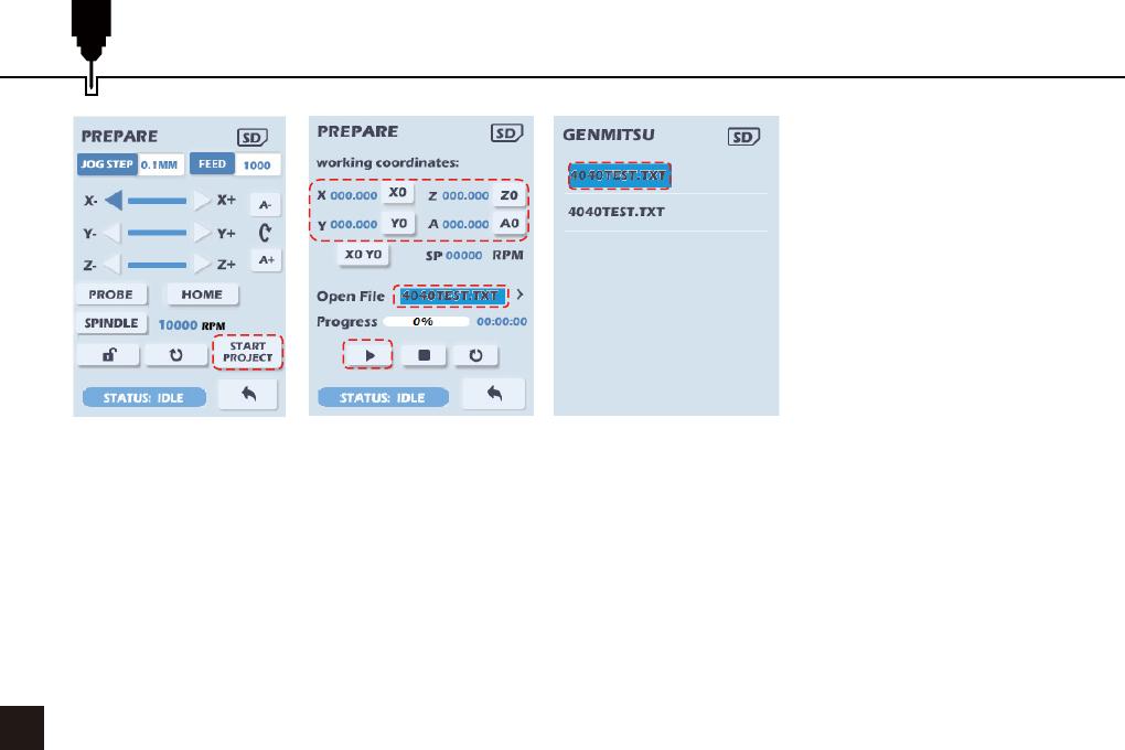
1. Once the router is in the
correct starting position
Select START PROJECT
and press the dial, the next
menu is shown.
2. To set the home positions
for the axes select and press
the X0 Z0 Y0 and A0 buttons
to zero the respective axis
to the current position. The
X0 Y0 button will set the
zero position for both the X
and Y axes.
1
3
2
5
4
3. Select the Open File selection bar and press the dial to select the Gcode file to open.
4. Scroll through the file list (only files in the root directory of the SD card are shown) and press the dial to open
the file. (To return to the previous menu without changing the selected file hold down the dial)
5. Once the start positions have been set and the Gcode file has been opened select the Start button and press
the dial to start machining.
6. As the file is processed the progress bar will update and the elapsed time for the job will be displayed. The
current position of the router in Work Coordinates will also be updated.
7. To pause execution select and press on the run button, a Feed hold will be executed, movement on the axes
will be halted but the positioning is retained. To resume the job select and press on the Run button, to abort it
press select and press the Stop button.
Limit Trigger Reset
09
1. If a limit switch is hit or a soft limit exceeded during the engraving process the offline controller will return to
the power-on interface, and the status bar in the lower left corner will show ALARM.
2. If any other error is returned the process will just stop.
3. Select PREPARE and press the dial.
4. Move the cursor to the Unlock icon and press the dial to unlock the router or select the HOME button.
Status
Indication
Unlock
Status Bar Tips and Status Comparison Chart
10
Status Bar Status Comparison
Idle Status
Homing Status
Jogging Status
Holding Status
Working Status
Sleeping Status
Checking Status
Alarm Status
Safety Door Status
Inhalt
Liste der Pakete
Optionales Zubehör (nicht im Lieferumfang enthalten)
Einführung
Sprache auswählen
Einstellung der Z-Sondenparameter
Bedienung
Starten Sie das Projekt
Limit Trigger Reset
Tipps für die Statusleiste und Statusvergleichstabelle
12
13
14
15
16
17
19
20
21
Liste der Pakete
12
4040 Offline-Steuerung
1
SD-Karte
3
500mm Offline
Controller Kabel
2
Kartenleser
4
Optionales Zubehör (nicht im Lieferumfang enthalten)
13
Sie finden diese auf www.sainsmart.com.
Staubschutzschuh
mit 42 mm Durchmesser
für 4040-PRO
Staubschutzschuh
mit 42 mm Durchmesser
für 4040-PRO
Staubschutzbleche
aus Metall
WC04A 1/4"-Schaft
Holzschnitzerei
Router Bits
Ziehen Sie die folgenden optionalen Upgrades oder Zubehörteile in Betracht, um Ihre CNC-Erfahrung zu
verbessern!
Einführung
14
1. Einstellrad: Drehen Sie das Einstellrad nach links und rechts, um den Cursor zur Auswahl der Tasten und
Werte zu bewegen. Drücken Sie das Rad nach unten, um zu bestätigen. Um einen numerischen Wert zu
ändern, wählen Sie das Feld aus, drehen Sie das Rad, um den Wert zu ändern, und drücken Sie dann zum
Einstellen auf das Rad. Für Listenwerte wählen Sie das Feld aus und drücken das Rad, um den nächsten
Wert in der Liste auszuwählen.
2. Offline Controller Kabelanschluss.
3. SD-Kartensteckplatz.
HINWEIS: Dieses Offline-Steuergerät ist nur für Genmitsu-Maschinen bestimmt und nicht mit den
Steuerplatinen anderer Hersteller kompatibel. Wenden Sie sich bei Fragen oder Problemen an unseren
Kundendienst.
1
3
2
Sprache auswählen
15
1. Drehen Sie das Rad, um SETTING auszuwählen, drücken Sie das Rad, um das SETTING-Menü
aufzurufen, wählen Sie die Sprache aus und drücken Sie das Rad, um die nächste Sprache auszuwählen.
2. Drücken Sie auf das Rad, um die angezeigte Sprache auszuwählen. Die Auswahl wird erst wirksam, wenn
Sie das Zurück-Symbol auswählen und das Display zum Startmenü zurückkehrt.
1
23
Einstellung der Z-Sondenparameter
16
(*Bitte messen und notieren Sie die Höhe des Werkzeug-Einstellblocks im Voraus).
1. Wählen Sie SETTING und drücken Sie auf das Rad.
2. Die Sondengeschwindigkeit ist die Geschwindigkeit in mm/min, mit der sich der Bohrer der Sondenbasis
nähert.
3. Wählen Sie "Tool Height", drücken Sie das Rad zur Auswahl und drehen Sie das Rad, um den Wert auf
die aufgezeichnete Höhe zu ändern.
4. Z-Anstiegshöhe ist die Höhe über der Unterseite der Sondenbasis, auf die der Bohrer nach dem Antasten
ansteigt.
5. Wählen Sie das Symbol Zurück und drücken Sie darauf, um zum vorherigen Bildschirm zurückzukehren.
1
2
3
Bedienung
17
1. Wählen Sie Vorbereiten, und drücken Sie auf das Rad.
2. Wählen Sie den Wert JOG STEP und drücken Sie auf das Rad, um durch die Jog-Distanzen zu schalten: xC
bedeutet kontinuierliches Jogging. Der Wert ist mm für die XYZ-Achsen und Grad für die A-Achse.
3. Wählen Sie den Wert FEED (Vorschub), drücken Sie zur Auswahl und drehen Sie dann das Rad, um die
Tippgeschwindigkeit zu ändern: Die Werte sind in mm/min.
4. Bewegen Sie den Cursor auf die Richtungspfeile von X, Y und Z. Drücken Sie den Drehknopf, um die
entsprechende Achse um den gewählten Tippschritt zu verfahren, wenn xC ausgewählt ist, halten Sie den
Drehknopf gedrückt, um den Tippbetrieb fortzusetzen, lassen Sie ihn los, um zu stoppen.
5. Bewegen Sie den Cursor auf A- oder A+ und drücken Sie das Rad, um die A-Achse zu drehen.
6. Bewegen Sie den Cursor auf HOME und drücken Sie das Rad, um eine Referenzfahrt durchzuführen.
1
Jogging
Distanz
Jogging-Geschwindigkeit
A-Achse
Drehrichtung
Position zu Hause
Bewegende
Richtung
Bedienung
18
7. Wählen Sie PROBE und drücken Sie das Rad, um die Z-Probe-Sequenz zu starten.
8. Wählen Sie SPINDEL, und drücken Sie auf das Rad, um die Spindel mit der angezeigten Drehzahl zu
starten oder zu stoppen.
9. Wählen Sie den RPM-Wert aus, und drehen Sie das Rad, um die Spindeldrehzahl einzustellen oder
anzupassen.
10. Wenn Sie die Symbole Entsperren oder Zurücksetzen auswählen und drücken, wird der Router entsperrt
oder zurückgesetzt.
11. Bewegen Sie den Cursor auf das Symbol Back (Zurück), und drücken Sie auf das Rad, um zum
vorherigen Menü zurückzukehren.
Spindeldrehzahl
Zurück
Z-Sonde Einstellung
Spindel Schalter
  • Page 1 1
  • Page 2 2
  • Page 3 3
  • Page 4 4
  • Page 5 5
  • Page 6 6
  • Page 7 7
  • Page 8 8
  • Page 9 9
  • Page 10 10
  • Page 11 11
  • Page 12 12
  • Page 13 13
  • Page 14 14
  • Page 15 15
  • Page 16 16
  • Page 17 17
  • Page 18 18
  • Page 19 19
  • Page 20 20
  • Page 21 21
  • Page 22 22
  • Page 23 23
  • Page 24 24
  • Page 25 25
  • Page 26 26
  • Page 27 27
  • Page 28 28
  • Page 29 29
  • Page 30 30
  • Page 31 31
  • Page 32 32
  • Page 33 33
  • Page 34 34
  • Page 35 35

Genmitsu 4040-PRO ユーザーマニュアル

タイプ
ユーザーマニュアル

Genmitsu 4040-PROは、卓上サイズの木材、アクリル、PVC、PCBなどの様々な素材を彫刻、切断、穴あけ、研磨、研削などに最適な、初心者にも使いやすい卓上CNCマシンです。

本体のフレームに高剛性アルミニウムを使用することで、剛性を確保しつつ軽量化を実現しており、高精度の加工が可能です。

また、ソフトウェアは日本語に対応しており、初心者でも簡単に操作することができ、付属のソフトウェアには一般的なGコードが内蔵されているため、複雑なプログラミングの知識がなくても、すぐに加工を始めることができます。