
www.metabo.com
W 850-100
W 850-115
W 850-125
WP 850-115
WP 850-125
WEV 850-125
W 1100-115
W 1100-125
WP 1100-115
WQ 1100-125
WEQ 1400-125
PRC 使用说明 5 en Original instructions 12

2
1
3
45
6 7
WP ...
10
11
12 13
14
15
17
11
16
C
18
D
12Z
W 850-100
12Y
12X
2
2
A
B
89
2

2
1
3
45
6 7
WP ...
10
11
12 13
14
15
17
11
16
C
18
D
12Z
W 850-100
12Y
12X
2
2
A
B
89
2
3
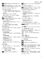
W 850-100
*1) 03606..
W 850-115
*1) 03607..
W 850-125
*1) 03608..
WP 850-115
*1) 03609..
WP 850-125
*1) 03610..
WEV 850-125
*1) 03611..
W 1100-115
*1) 03613..
W 1100-125
*1) 03614..
WP 1100-115
*1) 03612..
WQ 1100-125
*1) 10035..
WEQ 1400-125
*1) 00347..
Quick
---------
Ø
mm
(in)
100
(4)
115
(4
1
/
2
)
125
(5)
115
(4
1
/
2
)
125
(5)
125
(5)
115
(4
1
/
2
)
125
(5)
115
(4
1
/
2
)
125
(5)
125
(5)
t
max1
mm (in)
6 (
1
/
4
( 01)
3
/
8
)
t
max2
mm (in)
---------7,1 (
9
/
32
)
t
max3
mm (in)
6 (
1
/
4
)
t
max4
mm (in)
6 (
1
/
4
( 1,7)
9
/
32
)
M / l
- / mm
(in)
M 10 / 19,5
(
3
/
4
)
M 14 / 19,5 (
3
/
4
( 02 / 41 M)
25
/
32
)
n
min
-1
(rpm)
005110002100511
n
V
min
-1
(rpm)
-----
3000 -
11500
- ----
P
1
W
850 850850 850850 850 1100 1100 1100 1100 1400
P
2
W
047007007007007084025
m kg (lbs)
1,8 (4.0)
1,9
(4.2)
2,1 (4.7)2,2 (4.8)
a
h,SG
/
K
h,SG
m/s
2
7,5/1,57,5/1,5 8,0/1,57,5/1,5 8,0/1,58,0/1,5 7,0/1,57,5/1,5 7,0/1,57,5/1,5 7,5/1,5
a
h,DS
/
K
h,DS
m/s
2
<2,5/1,5
L
pA
/K
pA
dB(A)
3/783/883/783/88
L
WA
/K
WA
dB(A)
3/893/993/893/99
14.
*2) 2014/30/EU, 2006/42/EC, 2011/65/EU
*3) EN 60745-1:2009+A11:2010,
EN 60745-2-3:2011+A2:2013+A11:2014+A12:2014+A13:2015, EN 50581:2012
2018-08-16, Bernd Fleischmann
Direktor Produktentstehung & Qualität (Vice President Product Engineering & Quality)
*4) Metabowerke GmbH - Metabo-Allee 1 - 72622 Nuertingen, Germany

4
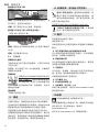
A
CLICK
CED 125: 6.26730
CED 125 Plus: 6.26731
B
6.30327
C
(12) (13)
(14)(1)
(2)
(11)
D
(M 14) 6.30706
(M 10) 34110205
D
max
= 100 mm (4“) 6.30346
D
max
= 115 mm (4
1
/
2
“) 6.30351
D
max
= 125 mm (5“) 6.30352
(M 14) 316047600
WQ 1100-125, WEQ 1400-125: (M 14) 6.30802
E
F
(12)
(14)
(1)

5
简体中文 PRC
使用说明
1. 符合标准声明
作为唯一责任人:我们特此声明,本公司的角磨
机(按型号和序列号 *1) 标识)符合全部相关指令
*2) 和标准 *3) 的要求。*4) 的相关技术文档 - 详见
第 3 页。
2. 正确使用
安装有麦太保原厂配件的角磨机,适用于干式研
磨、砂光、切断、钢丝刷磨金属、混凝土、石材以
及类似材料。
用户自行承担因使用不当造成的任何损坏的责任。
必须遵守通用事故预防规章和随附的安全资料。
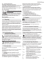
3. 一般安全说明
为了您自身的安全及保护您的电动工具,
请特别注意标有此符号的所有文本!
警告 – 仔细阅读使用说明可降低受伤风险。
警告 – 请仔细阅读所有安全警告和说明。
如
果未遵守这些安全警告和说明,可能导致电
击、火灾和
/
或人员重伤。
保存好所有警告和说明以备查阅。
转交电动工具时,请一并转交这些文件。
4. 特殊安全说明
4.1 砂磨、砂光、钢丝砂光、抛光或砂磨切割操
作的通用安全警告
a) 该电动工具是用于实现砂轮机、砂光机、钢丝
刷、抛光机或切断工具功能的。阅读随该电动工
具提供的所有安全警告、说明、图解和规定。不
了解以下所列所有说明将导致电击、着火和/或严
重伤害。
b) 该电动工具不适用于抛光等作业。若强行用该
工具进行不适当操作,则可能会造成危险和人身
伤害。
c) 不使用非工具制造商推荐和专门设计的附件。
否则该附件可能被装到你的电动工具上,而它不
能保证安全操作。
d) 附件的额定速度必须至少等于电动工具上标出
的最大速度。附件以比其额定速度大的速度运转
会发生爆裂和飞溅。
e) 附件的外径和厚度必须在电动工具额定能力范
围之内。不正确的附件尺寸不能得到充分防护或
控制。
f) 砂轮、法兰盘、靠背垫或任何其他附件的轴孔
尺寸必须适合于安装到电动工具的主轴上。带轴
孔的、与电动工具安装件不配的附件将会失稳、
过度振动并会引起失控。
g) 不要使用损坏的附件。在每次使用前要检查附
件,例如砂轮是否有碎片和裂缝,靠背垫是否有
的裂缝、撕裂或过度磨损,钢丝刷是否松动或金
属丝是否断裂。如果电动工具或附件跌落了,检
查是否有损坏或安装没有损坏的附件。检查和安
装附件后,让自己和旁观者的位置远离旋转附件
的平面,并以电动工具最大空载速度运行1分钟。
损坏的附件通常在该试验时会碎裂。
h) 戴上防护用品。根据适用情况,使用面罩、安
全护目镜或安全眼镜。适用时,戴上防尘面具、
听力保护器、手套和能挡小磨料或工件碎片的工
作围裙。眼防护罩必须挡住各种操作产生的飞
屑。防尘面具或口罩必须能过滤操作产生的颗
粒。长期暴露在高强度噪声中会引起失聪。
i) 让旁观者与工作区域保持一定安全距离。任何
进入工作区域的人必须戴上防护用品。工件或破
损附件的碎片可能会飞出并引起紧靠着操作区域
的旁观者的伤害。
j) 当在切割附件有可能切割到暗线或自身电线的
场所进行操作时,只能通过绝缘握持面来握住电动
工具。切割附件碰到一根带电导线可能会使电动工
具的外露金属零件带电并使操作者发生电击危险。
k) 使软线远离旋转的附件。如果控制不当,软线
可能被切断或缠绕,并使得你的手或手臂可能被
卷入旋转附件中。
l) 直到附件完全停止运动才放下电动工具。旋转
的附件可能会抓住表面并拉动电动工具而让你失
去对工具的控制。
m) 当携带电动工具时不要开动它。意外地触及旋
转附件可能会缠绕你的衣服而使附件伤害身体。
4
A
CLICK
CED 125: 6.26730
CED 125 Plus: 6.26731
B
6.30327
C
(12) (13)
(14)(1)
(2)
(11)
D
(M 14) 6.30706
(M 10) 34110205
D
max
= 100 mm (4“) 6.30346
D
max
= 115 mm (4
1
/
2
“) 6.30351
D
max
= 125 mm (5“) 6.30352
(M 14) 316047600
WQ 1100-125, WEQ 1400-125: (M 14) 6.30802
E
F
(12)
(14)
(1)

6
PRC 简体中文
n) 经常清理电动工具的通风口。电动机风扇会将
灰尘吸进机壳,过多的金属粉末沉积会导致电气
危险。
o) 不要在易燃材料附件操作电动工具。火花可能
会点燃这些材料。
p) 不要使用需用冷却液的附件。用水或其他冷却
液可能会导致电腐蚀或电击。
4.2 反弹和相关警告
反弹是因卡住或缠绕住的旋转砂轮、靠背垫、钢
丝刷或其他附件而产生的突然反作用力。卡住或
缠绕会引起旋转附件的迅速堵转,随之使失控的
电动工具在卡住点产生与附件旋转方向相反的
运动。
例如,如果砂轮被工件缠绕或卡住,伸入卡住点
的砂轮边缘可能会进入材料表面而引起砂轮爬出
或反弹。砂轮可能飞向或飞离操作者,这取决于
砂轮在卡住点的运动方向。在此条件下砂轮也可
能碎裂。
反弹是电动工具误用和/或不正确操作工序或条件
的结果,可以通过采取以下给出的适当预防措施
得以避免。
a) 保持紧握电动工具,使你的身体和手臂处于正
确状态以抵抗反弹力。如有辅助手柄,则要一直
使用,以便最大限度控制住起动时的反弹力或反
力矩。如采取合适的预防措施,操作者就可以控
制反力矩或反弹力。
b) 绝不能将手靠近旋转附件。附件可能会反弹碰
到手。
c) 不要站在发生反弹时电动工具可能移动到的
地方。反弹将在缠绕点驱使工具逆砂轮运动方向
运动。
d) 当在尖角、锐边等处作业时要特别小心。避免
附件的弹跳和缠绕。尖角、锐边和弹跳具有缠绕
旋转附件的趋势并引起反弹的失控。
e) 不要附装上锯链、木雕刀片或带齿锯片。这些
锯片会产生频繁的反弹和失控。
4.3 对磨削和砂磨切割操作的专用安全警告
a) 只使用所推荐的砂轮型号和为选用砂轮专门设
计的护罩。不是为电动工具设计的砂轮不能充分
得到防护,是不安全的。
b) 护罩必须牢固地装在电动工具上,且放置得最
具安全性,只有最小的砂轮部分暴露在操作人面
前。护罩帮助保护操作者免于受到爆裂砂轮碎片
和偶然触及砂轮的危险。
c) 砂轮只用作推荐的角途。例如:不要用切割砂
轮的侧面进行磨削。施加到砂轮侧面的力可能会
使其碎裂。
d) 始终为所选砂轮选用未损坏的、有恰当规格和
形状的砂轮法兰盘。合适的砂轮法兰盘支承砂轮
可以减小砂轮破裂的可能性。切割砂轮的法兰盘
可以不同于砂轮法兰盘。
e) 不要使用从大规格电动工具上用剩的磨损砂
轮。用于大规格电动工具上的砂轮不适于较小规
格工具的高速工况并可能会爆裂。
4.4 对砂轮切割操作的附加专用安全警告
a) 不要“夹”住切割砂轮或施加过大的压力。不
要试图做过深的切割。给砂轮施加过应力增加了
砂轮在切割时的负载,容易缠绕或卡住,增加了
反弹或砂轮爆裂的可能性。
b) 身体不要对着旋转砂轮,也不要站在其后。当
把砂轮从操作者身边的操作点移开时,可能的反
弹会使旋转砂轮和电动工具朝你推来。
c) 当砂轮被卡住或无论任何原因而中断切割时,
关掉电动工具并握住工具不要动,直到砂轮完全
停止。决不要试图当砂轮仍然运转时使切割砂轮
脱离切割,否则会发生反弹。调查并采取校正措
施以消除砂轮卡住的原因。
d) 不能在工件上重新起动切割操作。让砂轮达到
全速后再小心地重新进入切割。如果电动工具在工
件上重新起动,砂轮可能会卡住、爬出或反弹。
e) 支撑住板材或超大工件可使得砂轮卡住和反弹
的危险降到最低限度。大工件凭借自重而下垂。
必须在工件靠近切割线处和砂轮两侧近工件边缘
处放置支承。
f) 当进行“盲切割”进入墙体或其他盲区时要格
外小心。伸出的砂轮可能会割到煤气管或水管,
电线或由此引起反弹的物体。
4.5 砂光操作的专用安全警告
a) 当砂光时,不要使用超大砂盘纸。选用砂盘纸
时应按照制造商的推荐。超出砂光垫盘的大砂盘

7
简体中文 PRC
纸有撕裂的危险并且会引起缠绕、砂盘的撕裂或
反弹。
4.6 钢丝刷操作的专用安全警告
a) 要意识到即使正常操作时钢丝线也会随刷子甩
出。不要对钢丝刷施加过大的负荷而使得钢丝线
承受过应力。钢丝线可能会轻易刺入薄的衣服和/
或皮肤内。
b) 如果建议钢丝刷使用护罩,则不允许该护罩对
钢丝轮或钢丝刷有任何干扰。钢丝轮或钢丝刷在
工作负荷和离心力作用下直径会变大。
4.7 附加安全说明:
警告 – 务必始终佩戴护目镜。
如果制造商为研磨件配备了研磨介质,请在必要
时使用。
请遵循工具或配件制造商的规格说明!保护研磨
盘免受油脂侵蚀或冲撞损坏!
遵照制造商说明,细心存放并使用磨轮。
切勿使用切断砂轮进行粗加工作业!不得在切断
砂轮侧面施加压力。
工件必须平放并加以固定从而防止滑动,例如,
使用夹具固定。大型工件必须加以充分支承。
如果使用附带螺纹插入件的配件,则主轴末端不
得触及砂磨工具孔底。应确保配件螺纹长度足以
容纳主轴总长度。配件螺纹必须与主轴螺纹吻
合。请参见第 3 页和第 14 章“技术规格”,了解
主轴长度和螺纹的详细信息。
建议使用固定除尘系统,并在下游安装一个接地
故障断路器 (GFCI)。如果通过 GFCI 关闭角磨机,
则必须对其进行检查和清洁。
请参见第 9 章“清洁”,了解关于清洁电机的详细
信息。
切勿使用损坏的、偏心的或振荡的工具。
避免损坏燃气管道或水管、电线和承重墙(建筑
结构)。
在调试、更换或维修工具前,请将主电源拔下。
麦太保 S 型自动安全离合器(仅适用于 WQ 1100-
125 和 WEQ 1400-125)。在安全离合器激活时,
立即关闭本电钻!
必须更换损坏或破裂的附加手柄。切勿使用存在
问题的附加手柄操纵工具。
必须更换损坏或破裂的护罩。切勿使用存在问题
的护罩操纵工具。
该电动工具不适合抛光作业。工具使用不当会使
保修失效!电机可能会过热并损坏电动工具。我
们建议使用角抛光机进行抛光作业。
固定小工件,例如使用老虎钳固定。
减少粉尘暴露:
警告 - 使用此电动工具进行砂光、切割、研
磨、钻孔及其他施工作业时产生的部分粉尘
可能包含已知可导致癌症、先天缺陷或其他生殖危
害的化学物质。此类化学物质的一些示例包括:
- 含铅油漆中的铅,
- 砖块、水泥及其他石材产品的结晶二氧化硅,
以及
- 经化学处理的木材中的砷和铬。
暴露于此类物质所带来的风险取决于操作人员进
行此类工作的频率。为降低对这些化学物质的暴
露程度:在通风良好的区域作业,并穿戴经认可
的防护装备,例如专为过滤微小颗粒而设计的防
尘面罩等。
这同样适用于其他材料的粉尘,如木材(橡木或
榉木粉尘)、金属、石棉。已知可导致的其他疾
病包括过敏反应、呼吸系统疾病等。切勿吸入这
些粉尘。
遵守物料、员工、应用和应用地点的相关准则和
国家规定(例如,职业卫生与安全法规、废物处
理规范等)。
从源头收集产生的颗粒,避免在周围环境中沉积。
对于特殊作业,使用适当的配件。这样一来,肆
意侵入环境的微粒将减少。
使用适当的除尘装置。
通过以下措施降低粉尘暴露程度:
- 请勿将颗粒和废气流朝向自己或附近人员逃逸
或排放,也不要将其朝向沉积的粉尘。
- 使用除尘装置和/或空气净化器。
- 确保工作区域通风良好,使用真空吸尘器保证
工作区域的清洁。吹扫会使粉尘飞散。
- 使用吸尘器或水清洁防护服。请勿吹、打或刷。

8
PRC 简体中文
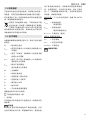
5. 概述
请参见第 2 页。
1 M 快速夹紧螺母*
2 支承法兰 *
3 主轴
4 主轴锁定按钮
5 滑动开关 *
6 手柄
7 速度调节轮 *
8 触发开关*
9 防启动锁*
10 侧向手柄
11 安全罩
12 2 孔螺母 *
13 2 孔扳手 *
14 夹紧螺母(免工具)*
15 夹子,用以手动拧紧∕松开(免工具)夹紧螺母 *
16 夹紧螺钉*
17 夹紧环*
18 护罩安装杆 *
* 取决于具体型号/不在交付范围内
6. 调试
调试前,请查看额定电源电压及频率(标在
铭牌上)是否与现有的电源相同。
务必在上游安装一个最大脱扣电流为 30 mA
的 GFCI。
6.1 安装附加手柄
作业中务必始终使用加装的手柄 (10)!将手
柄加装在工具左侧或右侧并固定到位。
6.2 安装护罩
出于安全原因,请务必一直使用为各个砂轮
相应配备的护罩。另请参见第 11 章。配件!
研磨护罩
专为粗砂轮、翼片砂光垫、金刚石切割片作业
设计。
W 850-100,W 850-115,W 850-125,
WP 850-115,WP 850-125,WEV 850-125,
W 1100-115,W 1100-125:
请参见第 2 页中的插图 C。
- 旋松夹紧螺钉 (16),直至护罩上的夹紧环 (17) 完
全松开。
- 将护罩 (11) 置于图示的位置。
- 转动护罩,直至闭合的防护部分面向操作者。
- 牢牢拧紧夹紧螺钉 (16)。确保护罩已固定到位 -
护罩 (11) 应无法转动。
WP 1100-115,WQ 1100-125,WEQ 1400-125:
请参见第 2 页中的插图 D。
- 拉住安装杆 (18)。将护罩 (11) 置于图示的位置。
- 松开安装杆,旋转护罩,直至安装杆卡合到位。
- 推动安装杆,转动护罩,直至闭合的防护部分
面向操作者。
- 确保护罩已固定到位:安装杆卡合到位,护罩
无法转动。
务必让护罩罩住配件至少
3.4 mm。
7. 安装磨轮
在更换任何配件之前:请将主电源线从插座
上拔出。工具必须切断,主轴必须静止。
出于安全考虑,请在进行研磨切断作业之前安
装研磨切断护罩(请参见第 11 章“配件”)。
7.1 锁定主轴
- 按下主轴锁定按钮 (4),手动转动主轴 (3),直至
主轴锁定按钮已卡合到位。
7.2 放置磨轮到位
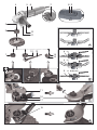
请参见第 2 页中的插图 A。
- 在主轴上安装支承法兰 (2)。一旦正确安装完毕,
法兰将无法在主轴上转动。
仅适用于 W 850-100:使用双孔扳手将支承法兰
拧到主轴上,使小套管(直径 16 mm)朝上。
- 将磨轮置于支承法兰 (2) 之上。磨轮在支承法兰
上必须摆平。
7.3 拧紧∕松开“M 快速”夹紧螺母(取决于产品
特点)
拧紧“M 快速”夹紧螺母 (1):

9
简体中文 PRC
仅适用于 WQ1100-125;WEQ 1400-125。
如果配件具有厚度超过 7.1 mm 夹柄,则不要
使用“M 快速”夹紧螺母!在此情况下,应
配合 2 孔扳手 (13) 使用 2 孔螺母 (12)。
- 锁定主轴(参见章节 7.1)。
- 将“M 快速”夹紧螺母 (1) 置于主轴 (3) 上,使
2 个凸耳卡入主轴的 2 个凹槽中。请参见第 2 页
中的插图。
- 顺时针手动拧紧“M 快速”夹紧螺母。
- 顺时针转动砂轮,拧紧“M 快速”夹紧螺母。
松开“M 快速”夹紧螺母 (1):
使用主轴锁定按钮 (4) 固定主轴之前,必须安
装“M 快速”夹紧螺母t (1)。
- 关机后工具继续工作。
- 在砂轮停止前按下主轴锁定按钮 (4)。松开“M
快速”夹紧螺母 (1)。
7.4 拧紧∕松开 2 孔螺母(取决于产品特点)
拧紧 2 孔螺母 (12):
2 孔螺母的两个侧面并不相同。按照以下步骤将双
孔螺母旋拧到主轴上:
请参见第 2 页中的插图 B。
- X) 对于薄研磨盘:
2 孔螺母 (12) 的边沿朝上,从而可安装固定薄
研磨盘。
Y) 对于厚研磨盘:
2 孔螺母 (12) 的边沿朝下,从而可将 2 孔螺母安
装固定在主轴上。
Z) 仅适用于 W 850-100:
2 孔螺母的套管朝上/朝下。
- 锁定主轴。使用 2 孔扳手 (13) 顺时针拧紧 2 孔
螺母 (12)。
松开 2 孔螺母:
- 锁定主轴(参见章节 7.1)。使用 2 孔扳手 (13)
逆时针松开 2 孔螺母 (12)。
7.5 拧紧∕松开(免工具)夹紧螺母
(取决于产品特点)
仅手动拧紧(免工具)夹紧螺母 (14)!
工具运行时,夹子 (15) 务必平放在夹紧螺母
(1) 上。
拧紧(免工具)夹紧螺母 (14):
如果配件具有厚度超过 6 mm 夹柄,则不要
使用夹紧螺母(免工具)!在此情况下,应
配合 2 孔扳手 (13) 使用 2 孔螺母 (12)。
- 锁定主轴(参见章节 7.1)。
- 上翻夹紧螺母上的夹子 (15)。
- 将夹紧螺母 (14) 置于主轴 (3) 上。请参见第 2 页
中的插图。
- 以顺时针方向手动拧紧夹子 (15) 的夹紧螺母。
- 再次下翻夹子 (15)。
松开(免工具)夹紧螺母 (14):
- 锁定主轴(参见章节 7.1)。
- 上翻夹紧螺母上的夹子 (15)。
- 逆时针手动转动夹紧螺母 (14),将其拧松。
注意:如果夹紧螺母 (14) 旋拧非常紧固,也可使
用 2 孔扳手拧松。
8. 使用
8.1 设定速度 (WEV 850-125)
使用拇指轮 (7) 设置建议的转速。(数字越小 = 速
度越低;数字越大 = 速度越高)
切割片,粗加工盘,杯形砂轮和金刚石切割片:
高速
钢丝刷:中速
砂磨板:低速到中速
注意:我们建议使用角抛光机进行抛光作业。
8.2 启动与关闭
务必始终双手操纵工具。
首先接通工具,然后将配件移向工件。
不得让工具吸入多余的粉尘和削屑。接通与
切断时,工具应远离沉积的粉尘。一旦接通
工具,只有在电机停止后才能放下工具。
避免意外启动:从主插座拔下插头或停电
时,务必关闭工具。
连续工作期间,如过电动工具脱手,它会继
续运转。因此,双手必须始终握住工具的手
柄,站稳,专心工作。

10
PRC 简体中文
配备滑动开关的工具:
0
I
5
接通:向前推移滑动开关 (5)。如需持续运行,则
向下斜压,直至其卡合到位。
切断:按下滑动开关 (5) 后端,然后松开。
配有拨片开关的工具(具有安全功能):
(带有 WP... 标识的工具)
0
I
8 989
接通:按箭头方向滑动防启动锁 (9) 并按下触发开
关 (8)。
切断:松开触发开关 (8)。
8.3 工作方向
研磨和砂光操作:
平稳均匀地压低工具并前后移动,以使工件表面
不至于过热。
粗研磨:将工具置于 30° - 40°角的位置,以确保实
现最佳作业效果。
研磨切断:
切断作业方向应始终与砂轮转动方向
相反(如图)。否则工具将失控并从
切口处反弹。以适于工件的速度平稳
均匀地移动工具。切勿倾斜、用力过
猛或左右摇摆。
钢丝刷磨:
平稳均匀地压低工具。
9. 清洁
在操作过程中,微粒可能会在电动工具内部堆积。
这会对电动工具降温造成不利影响。导电粉尘的堆
积会破坏电动工具的绝缘保护并引发电气危险。
应使用真空吸尘器或通过吹送干燥空气的方式,
定期彻底清洁电动工具的所有前后通风口。进行该
操作之前,请切断电动工具的电源并佩戴护目镜和
防尘面罩。吹出通风口时,确保有适当的吸力。
10. 故障排除(依设备不同而异)
电动工具无法启动。重启保护功能激活。如
果在工具处于开启状态时插入电源插头,或
者在中断后恢复供电,则工具不会启动。请
切断工具并再次启动。
仅适用于 WEV 850-125 和 WEQ 1400-125:
工具处于负载状态时速度会下降。工具负载
过大!使工具空转直至冷却。
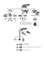
11. 配件
只能使用麦太保原厂配件。
请参见第 4 页。
仅能使用符合这些使用说明中所列要求及规格的
配件。
A 用于研磨切断作业的切割防护夹/护罩
专为切割片和金刚石切割片而设计。安装切割防
护夹后,护罩即为切割护罩。
B 研磨切断护罩
专为使用金刚石切割片切割石板而设计。使用适
当的除尘装置通过喷嘴吸除石屑。
C 手部防护
专为背垫、砂磨板、钢丝刷以及用于瓷砖的托
板、砂光垫、钢丝刷和金刚石钻头而设计。
在侧装的附加手柄下安装护手。
D 双孔螺母 (12)
E M 快速夹紧螺母 (1)
F 夹紧螺母(免工具)(14)
如需了解全部配件,请访问 www.metabo.com 或
参见配件目录。
12.维修
只能由合格的电工修理电动工具!
如果需要维修麦太保电动工具,请联系您当地的
麦太保代表。有关具体地址,请参见
www.metabo.com。
您可以从 www.metabo.com 下载配件列表。

11
简体中文 PRC
13.环境保护
产生的砂光粉尘包含危险物质:请勿随生活垃圾一
同处置,而应在危险废物的特定收集点进行处置。
有关废弃的工具、包装和配件的环保性处置及回
收,请遵循国家相关规定。
仅适用于欧盟国家/地区:不得将电动工具
与生活垃圾一同处置!根据欧盟关于废旧电
子和电气设备的指令 2012/19/EU 及其在国
家法律系统中的实施方案,废旧的电动工具必须
单独收集并以环保的方式回收。
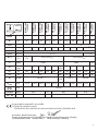
14. 技术规格
对规格的解释性说明请见第 3 页。取决于技术发展
的变化。
Ø = 配件最大直径
t
max,1
= 使用双孔螺母 (12) 时配件夹柄的最大允
许厚度
t
max,2
= 使用“M 快速”夹紧螺母 (1) 时配件夹柄
的最大允许厚度
t
max,3
= 使用(免工具)夹紧螺母 (14) 时配件夹
柄的最大允许厚度
t
max,4
= 粗加工盘/切割盘:
配件的最大允许厚度
M = 主轴螺纹
l = 砂磨主轴长度
n* = 空载转速(最大转速)
n
V
* = 空载转速(可调节)
P
1
= 额定输入功率
P
2
= 输出功率
m = 不含电源电缆的重量
测量值依照 EN 60745 确定。
工具的防护等级为 II 级
~ 交流电
引用的技术资料皆含有公差值在内(依照相关有
效标准)。
排放值
这些值可用来评估电动工具的排放量,以及
比较不同的电动工具。根据操作条件、使用的电
动工具及配件的情况,实际载荷可能会更高或更
低。当载荷较低,无法进行评估时,请让工具休
息一下。根据调整后的估计值,为使用者安排保
护措施,例如组织措施。
振动总值(三个方向的矢量和)依据 EN 60745
确定:
a
h, SG
= 振动排放值
(表面研磨)
a
h, DS
= 振动排放值
(使用砂磨板砂光)
K
h, SG/DS
= 不确定性(振动)
典型 A 荷重声音等级:
L
pA
= 声压等级
L
WA
= 声压功率等级
K
pA,
K
WA
= 不确定性
佩戴护耳器!

12
en ENGLISH
Original instructions
We, being solely responsible: Hereby declare that
these angle grinders, identified by type and serial
number *1), meet the requirements of all relevant
directives *2) and standards *3). Technical
documents for *4) - see page 3.
The
angle grinders, when fitted with original Metabo
accessories, are suitable for grinding, sanding,
separating and wire brushing metal, concrete,
stone
and similar materials without the use of water.
The user bears sole responsibility for any damage
caused by inappropriate use.
Generally accepted accident prevention
regulations and the enclosed sa
fety information
must be observed
.
For your own protection and for the
protection of your power tool, pay
attention to all parts of the text that are
marked with this symbol!
WARNING – Read the operating
instructions to reduce the risk of injury.
WARNING Read all safety warnings and
instructions. Failure to follow all safety
warnings and instructions may result in electric
shock, fire and/or serious injury
.
Keep
all safety instructions and information for
future reference.
Always include these documents when passing on
your power tool
.
4.
1Safety Warnings Common for Grinding,
Sanding, Wire Brushing or Abrasive Cut-
ting-Off Operations:
Us
e
a)
This power tool is intended to function as a
gr
inder, sander, wire brush or cut-off tool. Read
al
l
safety warnings,
instructions, illustrations
and sp
ecifications provided with this power
tool
. Failure to follow all the instructions may result
in electric shock, fire and/or serious injury.
b)
Operations such as polishing are not recom-
mended to be performed with this power tool
.
Operations for which the power tool was not
designed
may create a hazard and cause personal
injury
.
c)
Do not use accessories which are not specif-
ically designed and re
commended by the tool
manufacturer
. Just because the accessory can be
attached to your power tool, it does not assure safe
operation.
d) The rated speed of the accessory must be at
least equal to the maximum speed marked on
the power tool. Accessories running faster than
their rated speed can break and fly apart.
e) The outside diameter and the thickness of
your accessory must be within the capacity
rating of your power tool. Incorrectly sized acces-
sories cannot be adequately guarded or controlled.
f) Treaded mounting of accessories must
match the grinder spindle thread. For
accessories mounted by flanges, the arbour
hole of the accessory must fit the locating
diameter of the flange. Accessories that do not
match the mounting hardware of the power tool will
run out of balance, vibrate excessively and may
cause loss of control.
g) Do not use a damaged accessory. Before
each use, inspect accessories such as abra-
sive wheels for chips and cracks, backing pad
for cracks, tear or excess wear, wire brush for
loose or cracked wires. If a power tool or
accessory is dropped, check it for damage or
install an undamaged accessory. After
inspecting and installing an accessory, posi-
tion yourself and bystanders away from the
plane of the rotating accessory and run the
power tool at maximum no-load speed for one
minute. Damaged accessories will normally break
apart during this test time.
h) Wear personal protective equipment.
Depending on application, use a face shield,
safety goggles or safety glasses. As appro-
priate, wear dust mask, hearing protectors,
gloves and workshop apron capable of stop-
ping small abrasive or workpiece fragments.
The eye protection must be capable of stopping
flying debris generated by various operations. The
dust mask or respirator must be capable of filtering
particles generated by your operation. Prolonged
exposure to high intensity noise may cause hearing
loss.
i) Keep bystanders a safe distance away from
work area. Anyone entering the work area must
wear personal protective equipment.
Fragments
of workpiece or of a broken accessory may fly away
and cause injury beyond immediate area of opera-
tion.
j) Hold power tool by insulated gripping
surfaces only, when performing an operation
where the cutting accessory may contact
hidden wiring or its own cord. Cutting accessory
contacting a "live" wire may make exposed metal
parts of the power tool "live" and could give the
operator an electric shock.
k) Position the cord clear of the spinning acces-
sory. If you lose control, the cord may be cut or
snagged and your hand or arm may be pulled into
the spinning accessory.
1. Declaration of Conformity
2. Proper Use
3. General Safety Information
4. Special Safety Instructions

13
ENGLISH en
I) Never lay the power tool down until the
accessory has come to a complete stop
. The
spinning accessory may grip the surface and pull
the power tool out of your control.
m)
Do not run the power tool while carrying it at
your side
. Accidental contact with the spinning
accessory could snag your clothing, pulling the
accessory into your body.
n)
Regularly clean the power tool’s air vents.
The
motor’s fan will draw the dust inside the housing
and excessive accumulation of powdered metal
may cause electrical hazards.
o)
Do not operate the power tool near flam-
mable materials.
Sparks could ignite these mate-
rials.
p)
Do not use accessories that require liquid
coolants
. Using water or other liquid coolants may
result in electrocution or shock.
4.
2Kickback and Related Warnings
Kickback is a sudden reaction to a pinched or
snagged
rotating wheel, backing pad, brush or any
other
accessory. Pinching or snagging causes rapid
stalling of the rotating
accessory which in turn
causes the uncontrolled power tool to be forced in
the
direction opposite to the accessory’s rotation at
the point of jamming.
For example, if an abrasive wheel is snagged or
pinched by the workpiece, the edge of the wheel
that is entering into the pinch point can dig into the
surface of the material causing the wheel to climb
out
or kick out. The wheel may either jump toward or
away from the operator, depending on direction of
the wheel’s movement at the point of pinching.
Abrasive
wheels may also break under these condi-
tions.
Kickback is the result of power tool misuse and/or
incorrect operating procedures or conditions and
can be avoided by taking proper precautions as
given below.
a)
Maintain a firm grip on the power tool and
position your body and arm to allow you to
resist
kickback forces. Always use the auxiliary
handle, if provided, for maximum control over
kickback or torque reaction during start-up.
The operator can control torque reactions or kick
-
back forces, if proper precautions are taken.
b)
Never place your hand near the rotating
accessory.
Accessory may kickback over your
hand
.
c)
Do not position your body in the area
where
power tool will move if kickback occurs.
Kickback
will propel the tool in direction opposite to
the wheel’s movement at the point of snagging
d)
Use special care when working around
corners, sharp
edges etc. Avoid bouncing and
snagging
the accessory. Corners, sharp edges or
bouncing have a tendency to snag the rotating
accessory and cause loss of control or kickback
.
e)
Do not attach a saw chain woodcarving
blade or toothed saw blade.
Such blades create
frequent kickback and loss of control.
4.3Safety Warnings Specific for Grinding
and Abrasive Cutting-Off Operations:
a) Use only wheel types that are
recommended
for your power tool and the specific guard
designed for the selected wheel. Wheels for
which the power tool was not designed cannot be
adequately guarded and are unsafe.
b) The grinding surface of the centre
depressed
wheels must be mounted below the plane of
the guard lip. An improperly mounted wheel that
projects through the plane of the guard lip cannot be
adequately protected.
c) The guard must be securely attached to the
power tool and positioned for maximum
safety,
so the least amount of wheel is exposed
towards the operator. The guard helps to protect
the operator from broken fragments, accidental
contact with the wheel and sparks that could ignite
clothing.
d) Wheels must be used only for
recommended
applications.
For example: do not grind with the side of the
cut-off wheel. Abrasive cut-off wheels are
intended for peripheral grinding, side forces
applied
to these wheels may cause them to shatter.
e) Always use undamaged wheel flanges that
are of correct size and shape for your selected
wheel. Proper wheel flanges support the wheel
thus reducing the possibility of wheel breakage.
Flanges for cut-off wheels may be different from
grinding wheel flanges.
f) Do not use worn down wheels from larger
power tools. Wheels intended for larger power
tools are not suitable for the higher speed of a
smaller tool and may burst.
4.4Additional Safety Warnings Specific for
Abrasive Cutting-Off Operations:
a) Do not “jam” the cut-off wheel or apply
excessive pressure. Do not attempt to make
excessively deep cuts. Overstressing the wheel
increases the loading and susceptibility to twisting
or binding of the wheel in the cut and the possibility
of kickback or wheel breakage.
b) Do not position your body in line with and
behind the rotating wheel. When the wheel, at
the
point of operation, is moving away from your body,
the possible kickback may propel the spinning
wheel and the power tool directly at you.
c) If the wheel jams or if you interrupt a cut for
any reason, switch off the power tool and hold
the power tool motionless until the wheel
comes to a complete stop. Never attempt to
remove the cut-off wheel from the cut while the
wheel is in motion, otherwise kickback may
occur. Investigate and take corrective action to
eliminate the cause of the wheel jam.
d) Do not restart the cutting operation in the
workpiece. Let the wheel reach full speed and
carefully reenter the cut. The wheel may jam,
walk up or kickback if the power tool is restarted in
the workpiece.
e) Support panels or any oversized workpiece
to minimise the risk of wheel pinching and kick-

14
en ENGLISH
back. Large workpieces tend to sag under their own
weight. Supports must be placed under the work
-
piece near the line of cut and near the edge of the
workpiece on both sides of the wheel.
f)
Use extra caution when making a "pocket
cut"
into existing walls or other blind areas. The
protruding wheel may cut ga
s or water pipes, elec-
trical wiring or objects that can cause kickback
.
4.
5Safety Warnings Specific for Sanding
Operations:
a)
Do not use oversized sanding disc paper.
Follow
manufacturer's recommendations when
select
ing sanding paper. Larger sanding paper
extending beyond the sanding pad presents a
laceration
hazard and may cause snagging, tearing
of the disc or kickback.
4.
6Safety Warnings Specific for Wire Brush-
ing Operations:
a)
Be aware that wire bristles are lost by the
brush even during ordinary operation. Do not
overstress the wires by applying excessive
load to the brush.
The wire bristles can easily
penetrat
e light clothing and/or skin.
b)
If the use of a safety guard is recommended
for
wire brushing, do not allow any interference
of
the wire wheel or brush with the guard. Wire
wheel
or brush may expand in diameter due to work
load and centri
fugal forces.
4.
7Additional Safety Instructions:
WARNING – Always wear protective
goggles.
Use elastic cushioning layers if
they have been
supplied with the grinding media and if required
.
Observe the specifications of the tool or accessory
manufacturer! Protect discs from grease or impact
!
Grinding wheels must be stored and handled with
care in accordance with the manufacturer's
instructions
.
Never
use cut-off wheels for roughing work! Do not
apply pressure to the side of cut-off wheels
.
The
workpiece must lay flat and be secured against
slipping,
e.g. using clamps. Large workpieces must
be sufficie
ntly supported.
If accessories with threaded inserts are used, the
end of the spindle may no
t touch the base of the
hole
on the sanding tool. Make sure that the thread
in the accessory is long enough to accommodate
the full length of the spindle. The thread in the
accessory must match the
thread on the spindle.
See page 3 and the 14. Technical Specifications
chapter for more information on the spindl
e length
and thre
ad.
It is recommended to use a stationary extraction
system
and to place a ground fault circuit interrupter
(GFCI) downstream. If the angle grinder is shut
down
via the GFCI, it must be checked and cleaned.
See
the 9. Cleaning chapter for more information on
cleaning the motor
.
Damaged, eccentric or vibrating tools must not be
used.
Avoid damage to gas or water pipes, electrical
cables and load-bearing walls (building structure).
Pull the plug out of the socket before making any
adjustments, converting or servicing the machine.
Metabo S-automatic safety clutch (WQ1100-125,
WEQ 1400-125 only). When the safety clutch
activates, switch off the machine immediately!
A damaged or cracked additional handle must be
replaced. Never operate the machine with a
defective additional handle.
A damaged or cracked safety guard must be
replaced. Never operate a machine with a
defective
safety guard.
This power tool is not suitable for polishing work.
Improper use of the machine will void the warranty!
The motor may overheat and damage the electric
power tool. We recommend using our angle
polisher for polishing work.
Secure small workpieces, for example by clamping
them in a vice.
Reducing dust exposure:
WARNING - Some dust created by power
sanding, sawing, grinding, drilling, and other
construction activities contains chemicals known to
cause cancer, birth defects or other reproductive
harm. Some examples of these chemicals are:
-Lead from lead-based paints,
-Crystalline silica from bricks and cement and
other masonry products, and
-Arsenic and chromium from chemically treated
lumber.
Your risk from these exposures varies, depending
on how often you do this type of work. To reduce
your exposure to these chemicals: work in a well
ventilated area, and work with approved safety
equipment, such as those dust masks that are
specially designed to filter out microscopic
particles.
This also applies to dust from other materials such
as some timber types (like oak or beech dust),
metals, asbestos. Other known diseases are e.g.
allergic reactions, respiratory diseases. Do not let
dust enter the body.
Observe the relevant guidelines and national
regulations for your material, staff, application and
place of application (e.g. occupational health and
safety regulations, disposal).
Collect the particles generated at the source,
avoid
deposits in the surrounding area.
Use suitable accessories for special work. In this
way, fewer particles enter the environment in an
uncontrolled manner.
Use a suitable extraction unit.
Reduce dust exposure with the following measures:
-do not direct the escaping particles and the
exhaust air stream at yourself or nearby persons
or on dust deposits,
-use an extraction unit and/or air purifiers,

15
ENGLISH en
-ensure good ventilation of the workplace and keep
clean using a vacuum cleaner. Sweeping or
blowing stirs up dust.
-V
acuum or wash the protective clothing. Do not
blow, beat or brush.
See page 2.
1M-Quick clamping nut*
2Support flange *
3Spindle
4Spindle locking button
5Sliding on/off switch *
6Handle
7Speed adjustment wheel *
8Trigger*
9Switch-on lock*
10
Side handle
11
Safety cover
12
2-hole nut *
13
2-hole spanner *
14
Clamping nut (tool-free) *
15
Clip to tighten/release the (tool-free) clamping
nut manually *
16
Clamping screw*
17
Clamping ring*
18
Lever for safety guard attachment *
* depending on model / not in scope of delivery
Before commissioning, check that the rated
mains voltage and mains frequency stated on
the type plate match your power supply.
Always install an upstream GFCI with a
maximum trip current of 30 mA.
6.
1Attaching the additional handle
Always work with the additional handle (10)
attached! Attach the additional handle on the
left or right of the machine and secure
.
6.
2Attach the safety guard
For safety reasons, always use the safety
guard provided for the respective wheel! See
also chapter 11. Accessories!
Safety guard for grinding
Designed for work with roughing wheels, flap
sanding pads, diamond cu
tting discs.
W
850-100, W 850-115, W 850-125, WP 850-115,
WP 850-125, WEV 850-125, W 1100-115, W
1100-125
:
See illustration C on page 2.
-L
oosen the clamping screw (16) until the clamping
ring (17) on the safety guard expands sufficiently.
-P
lace the safety guard (11) in the position
indicated.
-T
urn the safety guard until the closed section is
facing the operator.
-Tighten the clamping screw (16) firmly. Make sure
that the guard is seated securely - you should not
be able to turn the safety guard (11).
WP 1100-115, WQ 1100-125, WEQ 1400-125:
See illustration D on page 2.
-Push and hold the lever (18). Place the safety
guard (11) in the position indicated.
-Release the lever and rotate the guard
until the lever latches.
-Push the lever and turn the safety guard until the
closed section is facing the operator.
-Make sure that the guard is attached securely:
The lever must engage and you should not be able
to turn the safety guard.
Use only accessories that
are covered by at least 3.4
mm by the safety guard.
Prior to any conversion work: pull the mains
plug out of the socket. The machine must be
switched off and the spindle at a standstill.
For reasons of safety, attach the cut-off
grinding guard before performing cut-off
grinding work (see Chapter 11. Accessories).
7.1Locking the spindle
-Press in the spindle locking button (4) and
turn the spindle (3) by hand until the spindle
locking button engages.
7.2Placing the grinding wheel in position
See illustration A on page 2.
-Fit the support flange (2) on the spindle. The
flange should not turn on the spindle when
properly attached.
Only W 850-100: Screw support flange with two-
hole spanner onto spindle so that the small collar
(with diameter 16 mm) is facing upwards.
-Place the grinding wheel on the support flange (2).
The grinding wheel must lay flat on the supporting
flange.
7.3Securing/Releasing the "M-Quick"
clamping nut (depending on features)
Securing the "M-Quick" clamping nut (1):
Only for WQ1100-125; WEQ 1400-125.
Do not use the "M-Quick" clamping nut if the
accessory has a clamping shank thicker than
7,1 mm! In this case, use the 2-hole nut (12) with 2-
hole spanner (13).
-Lock the spindle (see chapter 7.1).
-Position the "M-Quick" clamping nut (1) on the
spindle (3) so that the 2 lugs engage in the 2
grooves on the spindle. See illustration on page 2.
-Tighten the "M-Quick"clamping nut by turning it
clockwise by hand.
5. Overview
6. Commissioning
7. Attaching the grinding wheel

16
en ENGLISH
-Turn the grinding wheel firmly clockwise to tighten
the "M-Quick"clamping nut.
Releasing the “M-Quick” clamping nut (1):
The "M-Quick” clamping nut (1) must be
attached before the spindle locking button (4)
can hold the spindle!
-T
he machine continues to run after switching off.
-P
ress in the spindle locking button (4) just before
the grinding wheel stops. The "M-Quick"clamping
nut (1) is released.
7.
4Securing/Releasing the 2-hole nut
(depending on features)
Securing the 2-hole nut
(12):
The 2 sides of the two-hole nut are different.
Scre
w the two-hole nut onto the spindle as follows:
See illustration B on page 2.
-
X) For thin grinding discs:
The edge of the 2-hole nut (12) faces upwards so
that the thin grinding disc can be attached
securely.
Y) For thick grinding discs:
The edge of the two-hole nut (12) faces
downwards so that the two-hole nut can be
attached securely to the spindle.
Z) Only for W 850-100:
The collar of the two-hole nut faces downwards
and/or the flat surface faces upwards.
-L
ock the spindle. Turn the two-hole nut (12)
clockwise using the two-hole spanner (13) to
secure.
Releasing the 2-hole nut:
-L
ock the spindle (see chapter 7.1). Turn the two-
hole nut (12) anticlockwise using the two-hole
spanner (13) to unscrew.
7.
5Securing/releasing the (tool-free)
clamping nut
(depending on features)
Only tighten the (tool-free) clamping nut (14)
by hand!
For the machine to operate, the clip (15) must
always lie flat on the clamping nut (1).
To secure the (tool-free) clamping nut (14)
:
Do not use the clamping nut (tool-free) if the
accessory has a clamping shank thicker than
6m
m! In this case, use the 2-hole nut (12) with 2-
hole spanner (13)
.
-L
ock the spindle (see chapter 7.1).
-F
lip up the clip (15) on the clamping nut.
-F
it the clamping nut (14) on the spindle (3). See
illustration on page 2.
-T
ighten the clamping nut on the clip (15)
manually in a clockwise direction.
-F
lip down the clip (15) again .
Re
lease the (tool-free) clamping nut (14):
-L
ock the spindle (see chapter 7.1).
-F
lip up the clip (15) on the clamping nut.
-U
nscrew the clamping nut (14), turning it
anticlockwise manually .
Note:
If the clamping nut is very tightly secured (14),
you can also use a two-hole spanner to unscrew it.
8.1Setting the speed (WEV 850-125)
Set the recommended speed using the thumbwheel
(7). (Lower number = lower speed; higher number =
higher speed)
Cutting disc, roughing disc, cup wheel and diamond
cutting disc: high speed
Brush: medium speed
Sanding plate: low to medium speed
Note:
We recommend using our angle polisher for
polishing work.
8.2Switching on and off
Always guide the machine with both hands.
Switch on first, then guide the accessory
towards the workpiece.
The machine must not be allowed to draw in
additional dust and shavings. When switching
the machine on and off and keep it away from dust
deposits. After switching off the machine, only set it
down when the motor has come to a standstill.
Avoid inadvertent starts: always switch the
tool off when the plug is removed from the
mains socket or if there has been a power cut.
In continuous operation, the machine
continues running if it is forced out of your
hands. Therefore, always hold the machine with
both hands using the handles provided, stand
securely and concentrate.
Machines with a slide switch:
Switching on: push the slide switch (5) forwards.
For continuous operation, tilt it downwards until it
engages.
Switching off: press the rear end of the slide switch
(5) and release it.
Machine with paddle switch (with deadman
function):
(Machines with the designation WP...)
Switching on: Slide the switch-on lock (9) in the
direction of the arrow and press the trigger (8).
Switching off: Release the trigger switch (8).
8. Use
0
I
5
0
I
8 989
8.3Working Directions
Grinding and sanding operations:
Press down the machine evenly on the surface and
move it back and forth so that the surface of the
workpiece does not become too hot.
Rough grinding: position the machine at an angle of
30° - 40° for the best working results.
Cut-off grinding:
Always work against the run of the disc
(see illustration). Otherwise the
machine may kick back from the cut in
an out of control manner. Guide the
machine evenly at a speed suitable for
the material being processed. Do not tilt, apply
excessive force or sway from side to side.
Wire brushing:
Press down the machine evenly.
Particles may become deposited inside the power
tool during operation. This impairs the cooling of the
power tool. Conductive build-up can impair the
protective insulation of the power tool and create an
electrical hazard.
The power tool should be cleaned regularly, often
and thoroughly through all front and rear air vents
using a vacuum cleaner or by blowing in dry air.
Before doing so, separate the power tool from the
power source and wear protective goggles and a
dust mask. Ensure appropriate suction is available
when blowing out vents.
The machine does not start. Restart
protection is active. If the mains plug is
inserted with the machine switched on or if the
power supply is restored following an interruption,
the machine does not start up. Switch the machine
off and back on again.
WEV 850-125, WEQ 1400-125 only:
The speed drops while the machine is
under load. There is too much load on the
machine! Allow the machine to run at idle
speed until it has cooled down.
Use only genuine Metabo accessories.
See page 4.
Only use accessories which fulfil the requirements
and specifications listed in these operating
instructions.
ACutting guard clip / guard for cut-off
grinding
Designed for work with cutting disc and diamond
cutting discs. Once the cutting guard clip is fitted,
the safety guard becomes a cutting guard.
BExtraction guard for cut-off grinding
Designed for cutting through stone slabs with
diamond cutting discs. With nozzle for extracting
stone dust using a suitable extraction unit.
CHand protection
Intended for work with backing pads, sanding
plates, wire brushes and support plates, sanding
pads, wire brushes and diamond drill bits for tiles.
Install the hand guard under the additional side-
mounted handle.
DTwo hole nut (12)
EM-Quick clamping nut (1)
FClamping nut (tool-free) (14)
For a complete range of accessories, see
www.metabo.com or the accessories catalogue.
Repairs to electrical tools must ONLY be
carried out by qualified electricians!
Contact your local Metabo representative if you
have Metabo power tools requiring repairs. See
www.metabo.com for addresses.
You can download a list of spare parts from
www.metabo.com.
The sanding dust generated may contain
hazardous materials: do not dispose of dust with
household waste, but at a special collection point
for hazardous waste.
Observe national regulations on environmentally
compatible disposal and on the recycling of disused
machines, packaging and accessories.
Only for EU countries: never dispose of
power tools in your household waste!
According to European Directive 2012/19/EU
on Waste from Electric and Electronic Equipment
and implementation in national law, used power
tools must be collected separately and recycled in
an environmentally-friendly manner.
Explanatory notes on the specifications on page 3.
Subject to change in accordance with technical
progress.
Ø=max. diameter of the accessory
t
max,1
=max. permitted thickness of the clamping
shank on accessory when using two-hole
nut (12)
t
max,2
=max. permitted thickness of clamping
shank on accessory when using "M-
Quick" clamping nut (1)
t
max,3
=max. permitted thickness of clamping
shank on accessory when using (tool-
free) clamping nut (14)
t
max,4
=roughing disc/cutting disc:
max. permitted thickness of accessory
M=Spindle thread
l=Length of the sanding spindle
n* =No-load speed (maximum speed)
n
V
*=No-load speed (adjustable)
9. Cleaning
10. Troubleshooting
(equipment-specific)
11. Accessories
12. Repairs
13. Environmental Protection
14. Technical Specifications

17
ENGLISH en
-Turn the grinding wheel firmly clockwise to tighten
the "M-Quick"clamping nut.
Releasing the “M-Quick” clamping nut (1):
The "M-Quick” clamping nut (1) must be
attached before the spindle locking button (4)
can hold the spindle!
-The machine continues to run after switching off.
-Press in the spindle locking button (4) just before
the grinding wheel stops. The "M-Quick"clamping
nut (1) is released.
7.4Securing/Releasing the 2-hole nut
(depending on features)
Securing the 2-hole nut (12):
The 2 sides of the two-hole nut are different.
Screw the two-hole nut onto the spindle as follows:
See illustration B on page 2.
- X) For thin grinding discs:
The edge of the 2-hole nut (12) faces upwards so
that the thin grinding disc can be attached
securely.
Y) For thick grinding discs:
The edge of the two-hole nut (12) faces
downwards so that the two-hole nut can be
attached securely to the spindle.
Z) Only for W 850-100:
The collar of the two-hole nut faces downwards
and/or the flat surface faces upwards.
-Lock the spindle. Turn the two-hole nut (12)
clockwise using the two-hole spanner (13) to
secure.
Releasing the 2-hole nut:
-Lock the spindle (see chapter 7.1). Turn the two-
hole nut (12) anticlockwise using the two-hole
spanner (13) to unscrew.
7.5Securing/releasing the (tool-free)
clamping nut
(depending on features)
Only tighten the (tool-free) clamping nut (14)
by hand!
For the machine to operate, the clip (15) must
always lie flat on the clamping nut (1).
To secure the (tool-free) clamping nut (14):
Do not use the clamping nut (tool-free) if the
accessory has a clamping shank thicker than
6mm! In this case, use the 2-hole nut (12) with 2-
hole spanner (13).
-Lock the spindle (see chapter 7.1).
-Flip up the clip (15) on the clamping nut.
-Fit the clamping nut (14) on the spindle (3). See
illustration on page 2.
-Tighten the clamping nut on the clip (15)
manually in a clockwise direction.
-Flip down the clip (15) again .
Release the (tool-free) clamping nut (14):
-Lock the spindle (see chapter 7.1).
-Flip up the clip (15) on the clamping nut.
-Unscrew the clamping nut (14), turning it
anticlockwise manually .
Note:
If the clamping nut is very tightly secured (14),
you can also use a two-hole spanner to unscrew it.
8.1Setting the speed (WEV 850-125)
Set the recommended speed using the thumbwheel
(7). (Lower number = lower speed; higher number =
higher speed)
Cutting disc, roughing disc, cup wheel and diamond
cutting disc: high speed
Brush: medium speed
Sanding plate: low to medium speed
Note: We recommend using our angle polisher for
polishing work.
8.2Switching on and off
Always guide the machine with both hands.
Switch on first, then guide the accessory
towards the workpiece.
The machine must not be allowed to draw in
additional dust and shavings. When switching
the machine on and off and keep it away from dust
deposits. After switching off the machine, only set it
down when the motor has come to a standstill.
Avoid inadvertent starts: always switch the
tool off when the plug is removed from the
mains socket or if there has been a power cut.
In continuous operation, the machine
continues running if it is forced out of your
hands. Therefore, always hold the machine with
both hands using the handles provided, stand
securely and concentrate.
Machines with a slide switch:
Switching on: push the slide switch (5) forwards.
For continuous operation, tilt it downwards until it
engages.
Switching off: press the rear end of the slide switch
(5) and release it.
Machine with paddle switch (with deadman
function):
(Machines with the designation WP...)
Switching on: Slide the switch-on lock (9) in the
direction of the arrow and press the trigger (8).
Switching off: Release the trigger switch (8).
8. Use
0
I
5
0
I
8 989
8.3Working Directions
Grinding and sanding operations:
Press down the machine evenly on the surface and
move it back and forth so that the surface of the
workpiece does not become too hot.
Rough grinding: position the machine at an angle of
30° - 40° for the best working results.
Cut-off grinding:
Always work against the run of the disc
(see illustration). Otherwise the
machine may kick back from the cut in
an out of control manner. Guide the
machine evenly at a speed suitable for
the material being processed. Do not tilt, apply
excessive force or sway from side to side.
Wire brushing:
Press down the machine evenly.
Particles may become deposited inside the power
tool during operation. This impairs the cooling of the
power tool. Conductive build-up can impair the
protective insulation of the power tool and create an
electrical hazard.
The power tool should be cleaned regularly, often
and thoroughly through all front and rear air vents
using a vacuum cleaner or by blowing in dry air.
Before doing so, separate the power tool from the
power source and wear protective goggles and a
dust mask. Ensure appropriate suction is available
when blowing out vents.
The machine does not start. Restart
protection is active. If the mains plug is
inserted with the machine switched on or if the
power supply is restored following an interruption,
the machine does not start up. Switch the machine
off and back on again.
WEV 850-125, WEQ 1400-125 only:
The speed drops while the machine is
under load. There is too much load on the
machine! Allow the machine to run at idle
speed until it has cooled down.
Use only genuine Metabo accessories.
See page 4.
Only use accessories which fulfil the requirements
and specifications listed in these operating
instructions.
ACutting guard clip / guard for cut-off
grinding
Designed for work with cutting disc and diamond
cutting discs. Once the cutting guard clip is fitted,
the safety guard becomes a cutting guard.
BExtraction guard for cut-off grinding
Designed for cutting through stone slabs with
diamond cutting discs. With nozzle for extracting
stone dust using a suitable extraction unit.
CHand protection
Intended for work with backing pads, sanding
plates, wire brushes and support plates, sanding
pads, wire brushes and diamond drill bits for tiles.
Install the hand guard under the additional side-
mounted handle.
DTwo hole nut (12)
EM-Quick clamping nut (1)
FClamping nut (tool-free) (14)
For a complete range of accessories, see
www.metabo.com or the accessories catalogue.
Repairs to electrical tools must ONLY be
carried out by qualified electricians!
Contact your local Metabo representative if you
have Metabo power tools requiring repairs. See
www.metabo.com for addresses.
You can download a list of spare parts from
www.metabo.com.
The sanding dust generated may contain
hazardous materials: do not dispose of dust with
household waste, but at a special collection point
for hazardous waste.
Observe national regulations on environmentally
compatible disposal and on the recycling of
disused
machines, packaging and accessories.
Only for EU countries: never dispose of
power tools in your household waste!
According to European Directive 2012/19/EU
on Waste from Electric and Electronic Equipment
and implementation in national law, used power
tools must be collected separately and recycled in
an environmentally-friendly manner.
Explanatory notes on the specifications on page 3.
Subject to change in accordance with technical
progress.
Ø=max. diameter of the accessory
t
max,1
=max. permitted thickness of the clamping
shank on accessory when using two-hole
nut (12)
t
max,2
=max. permitted thickness of clamping
shank on accessory when using "M-
Quick" clamping nut (1)
t
max,3
=max. permitted thickness of clamping
shank on accessory when using (tool-
free) clamping nut (14)
t
max,4
=roughing disc/cutting disc:
max. permitted thickness of accessory
M=Spindle thread
l=Length of the sanding spindle
n* =No-load speed (maximum speed)
n
V
*=No-load speed (adjustable)
9. Cleaning
10. Troubleshooting
(equipment-specific)
11. Accessories
12. Repairs
13. Environmental Protection
14. Technical Specifications

18
en ENGLISH
P
1
=Rated input power
P
2
=Power output
m=
Weight without mains cable
Measured values determined in conformity with
EN
60745.
Machine in protection class II
~
AC power
The technical specifications quoted are subject to
tolerances (in compliance with relevant valid
standards)
.
Emission values
These values make it possible to assess the
emissions from the power tool and to compare
different
power tools. The actual load may be higher
or lower depending on operating conditions, the
condition
of the power tool or the accessories
used.
Please allow for breaks and periods when the load
is lower for assessment purposes. Arrange
protective measures for the user, such as
organisational measures based on the adjusted
estimates.
Total
vibration value
(vector sum of three
directions)
determined in accordance with EN 60745:
a
h, SG
=Vibration emission value
(surface grinding)
a
h, DS
=Vibration emission value
(sanding with sanding plate)
K
h,SG/DS
=Uncertainty (vibration)
Typical A-effective perceived sound level
s
:
L
pa
=Sound-pressure level
L
WA
=Acoustic power level
K
pA
, K
WA
=Uncertainty
Wear ear protectors!


Metabowerke GmbH
Metabo-Allee 1
72622 Nuertingen
Germany
www.metabo.com
170 27 5870 - 1018
-
 1
1
-
 2
2
-
 3
3
-
 4
4
-
 5
5
-
 6
6
-
 7
7
-
 8
8
-
 9
9
-
 10
10
-
 11
11
-
 12
12
-
 13
13
-
 14
14
-
 15
15
-
 16
16
-
 17
17
-
 18
18
-
 19
19
-
 20
20


