MODEL D System Exclusive Commands
Some parameters in the MODEL D synthesizer can be
changed using MIDI system exclusive (SysEx) commands.
A MIDI utility such as the popular MIDI OX can be used to
send the SysEx command data string to the MODEL D using
the USB MIDI conection between a host computer and
the MODEL D.
SysEx Data Format
The following data format is used when creating a
SysEx message (with the data beginning with F0 and
ending with F7).
F0 00 20 32 aa bb cc dd ee F7
The various items in this SysEx data string are
described below:
Item Description
00 20 32
Manufacturer
SysEx ID number
(Behringer GmbH)
aa Reserved
bb Device ID: 00-0xF (must match hardware
device ID), or 7F to address all devices.
Note: This is the same as the Poly Chain ID.
It is not the MIDI Channel
cc Main parameter number (see Command
Table below)
dd Sub parameter number (see Command
Table below)
ee Parameter value MSB (will be zero unless the
parameter value is greater than 127)
Parameter value LSB (Range is 0 to 127)
(see Command Table below)
Command Table
*Note: If you use SysEx instead of the recommended A-440
method to turn on the Poly Chain, then the Poly Chain
Device ID of other units in the chain is not set automatically.
You have to use SysEx to set the Poly Chain ID of the rst
MODEL D to Device ID=0, the second MODEL D to ID=1,
the third MODEL D to ID=3 and so on. All MODEL D units
must have the same MIDI channel.
Retriggering Style
These examples show the di erence between the old and
new retriggering styles
Example
Old style
(v1.0.5)
New style
(v1.0.6)
Press and hold note A.
Note A is playing.
Then press and hold
note B. Note B is playing
(A stop). Release note A.
Retrigger No Retrigger
Press and hold note A. Note A
is playing. Then press and hold
note B. Note B is playing
(A stop). Release note B.
Retrigger Retrigger
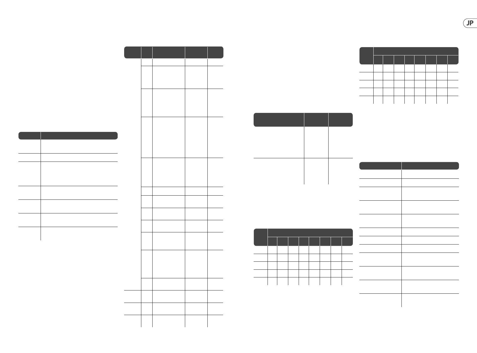
Poly Chain Style
These two tables show the di erence between old and new
poly chain style.
TABLE OF NOTE RESPONSE -- Old poly chain style
Poly chain
Device
no.
How many notes are playing
01234567
1O Note1 Note1 Note1 Note1 Note1 Note1 Note1
2O Note1Note2 Note2 Note2 Note2 Note2 Note2
3O Note1Note1Note3 Note3 Note3 Note3 Note3
4 O Note1 Note1 Note1 Note4 Note4 Note4 Note4
5 O Note1 Note1 Note1 Note1 Note5 Note5 Note5
TABLE OF NOTE RESPONSE -- New poly chain style
Note: Turning on the Poly Chain will a ect the note
priority function
Command Examples
Note: All command parameters should be in
hexadecimal format.
Poly chain
Device
no.
How many notes are playing
01234567
1O Note1 Note1 Note1 Note1 Note1 Note1 Note1
2O O Note2 Note2 Note2 Note2 Note2 Note2
3O O o Note3 Note3 Note3 Note3 Note3
4 O O O O Note4 Note4 Note4 Note4
5 O O O O O Note5 Note5 Note5
Function SysEX Command String
Set MIDI Channel to 13 F0 00 20 32 00 7F 0A 00 00 0C F7
Set Key Priority to last F0 00 20 32 00 7F 0A 01 00 02 F7
Turn on Multi Trigger
(1.05 style)
F0 00 20 32 00 7F 0A 02 00 01 F7
Set Pitch B end
semitone to 11
F0 00 20 32 00 7F 0A 03 00 0B F7
Set MIDI IN Transpose
to +8
F0 00 20 32 00 7F 0A 06 00 14 F7
Set Note C5 as Zero Volts F0 00 20 32 00 7F 0A 07 00 48 F7
Turn on Poly Chain F0 00 20 32 00 7F 0A 08 00 01 F7
Set Device ID to 5 F0 00 20 32 00 7F 0A 09 00 05 F7
Disable MIDI
Channel Switches
F0 00 20 32 00 7F 0A 0A 00 01 F7
Set Modulation Curve
to Medium
F0 00 20 32 00 7F 0A 0B 00 01 F7
Make pitch bend
range e ective
F0 00 20 32 00 7F 0A 0C 00 01 F7
Set poly chain style to
old style
F0 00 20 32 00 7F 0A 0D 00 01 F7
cc (Main) dd
(Sub)
Description (Para
Range)
Default
0xA
Global
Setting
00 MIDI Channel 0 to 15 0
01 Key Priority
(In poly chain mode,
note priority will be
restricted to ’LOW’)
0-LOW
1-HIGH
2-LAST
0- LOW
02 Multi Trigger 0-OFF
1-ON
(1.05 style)
2-ON
(1.06 style)
0- OFF
03 Pitch Bend
semitones
(Pitch wheel range)
E ective when pitch
bend range not
xed. See “OC Pitch
bend mode” below
0 to 12 12
06 MIDI IN Transpose 0 to 24
The range is
-12 to + 12,
so 12 is no
transpose
12
07 MIDI Note Zero Volts 0 to 127 36
08 Poly Chain* see
note below
0-OFF, 1-ON 0- OFF
09 Device ID
(Poly Chain ID)
0-15 0
0A Enable/Disable MIDI
Channel Switches
0- Enable
1- Disable
0-Enable
0B Modulation Curve 0- Soft
1- Med
2- Hard
0- Soft
OC Pitch Bend Mode 0- PitchBend
Range Fixed
1- PitchBend
Range
Settable
0- Fixed
OD Poly Chain Style 0- New Style
1- Old Style
0- New
Style
0xB
Restore Global
Settings
0xE
Start User Pitch
CV Calibration
0xF
Restore Default
CV Calibration
18 19MODEL D


