
Gas Built-in Hob
2 BURNER GAS HOB
ER70762HK Town gas model
3 BURNER GAS HOB
ER70962HK Town gas model
ER70926HK, ER70922HK
LPG models
Installation and operating instructions
(04/2011)

2
Dear Customer,
We thank you and congratulate you on your choice. This practical appliance,
which is modern and functional, has been manufactured from top-quality
materials which have been subjected to a strict quality control during the entire
manufacturing process have been carefully tested so that they will meet all your
cooking needs.
We strongly advise you to read through these simple instructions, so as to ensure
that you get perfect results from the moment you first use this appliance. This
book contains important information, not only on how to use the appliance, but
also on maintenance and safety.
When our products are being transported, they must be provided with suitable
protective packaging. However we have reduced our packaging to the bare
essentials, and the materials are all completely recyclable. You too can contribute
to the conservation of the environment by depositing the packaging in the nearest
recycling container. Used oil should not be poured down the sink, as this causes
serious damage to the environment. Pour it into a sealable container and take it to
a recycling point, or simply put in your rubbish bin. It will then finish up in a
controlled landfill site, which though it is not the perfect solution, it does prevent
water pollution. Your children and yourself will appreciate this. Before you get rid
of any old appliance, make sure you render it useless, and then take it to a centre
for recovering recyclable materials. Ask your local authorities for details on the
nearest centre to your home.
IMPORTANT:
Under the Gas Safety (Registration of Gas Installers and Gas Contractors)
Regulations, only registered gas installers (registered to the appropriate
class) employed by registered gas contractors can personally carry out gas
installation work. “Gas Installation Work” includes the fabrication,
connection, or replacement of gas pipework, appliances and fitting.

3
Contents
Installation Instructions……………..…………..………………..4-5
Servicing Instructions……………..…………..………………….6
Minor Adjustments…………………………………….……….….6
Fault Isolation Chart…...………………….………………………6
Operating Instructions…………………………………………….7
Hints On Use of The Hotplate……………………….……..…….8
Recognizing Abnormal Operation…………………..…………...9
Specification Tables..…...………………………………..….…...10

4
INSTALLATION INSTRUCTIONS
DATA PLATE DETAILS:
The data plate is located on the front side of the tray.
CHECK THAT THE DATA PLATE SHOWS THAT THE APPLIANCE IS
SUITABLE FOR THE AVAILABLE GAS SUPPLY.
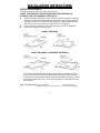
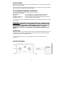
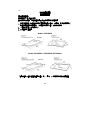
1. Before installing the appliance check that the location provides the required
clearances from combustible materials and if necessary provide protection
to adjacent surfaces as required by the regulations. Make provision for the
gas supply to be connected in the position shown in Diagram A.
2. Cut the opening in the bench top to the dimensions shown in diagram B.
3. Remove the hotplate from the carton.
Models: ER70762HK
Models: ER70962HK / ER70926HK / ER70922HK
If clearance between side and rear walls and periphery of the burner is less
than 150mm, the walls must be protected with a non-combustible material.
The protection must extend a minimum distance of 450mm above the burner.
Horizontal surfaces less than 750mm vertically above the hotplate must also
be protected.
Refer – Gas fitting manual. Position of gas inlet : See diagram above
Depth from top of glass to bottom of tray : 70mm excluding regulator
Gas Inlet
Gas inlet

5
4. Install the hotplate in the cut-out (See diagram B).
5. The gas connection to the regulator is 1/2” BSP. The regulator should be held by a
spanner on the flats provided when making the joins. Turn the gas on and check for
leaks using a soap solution and brush around all joints and connections.
Pressure test point:
- This is provided in the gas regulator.
- Remove the screw, connect the hose from the pressure gauge.
- Turn on the gas to the large burner and manually light the burner.
- The pressure is shown on the data plate.
- To increase the pressure, loosen locking nut and turn clockwise.
- Disconnect gauge and replace test point screw.
6. Test the appliance:
- Depress the control knob and turn to full flame setting.
- The burner will ignite. Adjust control knob to desired setting. Normally, no
adjustment should be necessary.
- If any problems occur, refer to the servicing instructions or fault isolation chart.
7. Instruct the user to keep the users instructions manual.
If any of the above procedures do not produce satisfactory results, the
agent’s service department should be consulted for more specialized assistance.
8. The cooktop is fitted with the flame failure device that cuts off the gas supply when
burner flame extinguishes suddenly or abnormally in order to avoid the gas leakage.
9. Room Ventilation - This cooktop must be installed in a room that has permanent
ventilation to effect the correct operation of the appliances and also to provide
adequate ventilation. This airflow must exceed 20m³ via permanent vented openings
in the walls of the room and these must have a section of 100cm² minimum. They
must be constructed in a manner so as to avoid any possible blockages. The airflow
can also be drawn indirectly from an adjacent room provided it complies with any
local regulations to vent any fumes outdoors.
WARNING:
- Do not spray aerosols in the vicinity of this hotplate while it is in operation.
- Some propellant gases can break down when heated and produce corrosive vapours
which will attack some materials.
- Articles which are made of flammable materials should not be stored in drawers or
cupboards immediately below this hotplate.
- The silicone rubber gasket should not be removed under any circumstances. In the
event that any protective rubber gasket is dropped off or damaged, the consumer
should cease forthwith the use of the unit until it is duly rectified.
- Do not store articles within 50mm of the bottom of the hotplate casing.
- Do not touch spark igniter while lighting the burner.
- When the appliance is installed in a marine craft or in caravans, it shall not be used as
a space heater.

6
SERVICING INSTRUCTIONS
MINOR ADJUSTMENTS
Access to By Pass Screw
Access to manifold, gas taps and
burner assembly
- Light the burner and turn to minimum
setting (marked small flame).
- The flame should be stable on
minimum setting and should not
extinguish when passing from
maximum setting to low setting.
- If adjustment is necessary, remove
the control knob by pulling upward.
The bypass screw is accessible via
the control knob spindle. Turn the
bypass screw anti-clockwise to
increase the turn-down rate.
- Remove glass hob and control knobs.
- To remove gas cocks. Unscrew the
locking nut (between cock and burner).
Remove screws, the cock can now be
removed from the manifold. If access to
the barrel is required, remove two screws
which retain spindle to body. If
lubricating the mechanism use Regosine
Moly LM or other approved grease.
To replace electrode.
- Remove screw from the clamp holding
the electrode and thermocouple and note
the adjustment setting height of each.
Replace electrode and then fit clamp and
screw.
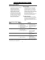
FAULT ISOLATION CHART
FAULT CAUSES REMEDY
Burner will not light 1. Air in gas line
2. Blockage in line
3. Ignition not sparking
4. Flame failure device faulty
5. Check the battery
(applicable to DC version)
1. Purge gas line
2. Trace back and clear
3. Check lead and electrode
4. Replace thermocouple
and test
5. Replace the battery
Burner lights back to injector 1. Excessive lint up of
burner mixing tube
2. Excessive gas pressure
1. Remove and clean burner
2. Check gas regulator
pressure. Adjust if
necessary.
Burner has explosive ignition 1. Excessive gas pressure 1. Check gas regulator
pressure. Adjust if
necessary.
Ignitor not sparking 1. Electrode gap
2. Ignitor connections
1. Check gap, adjust if not
between 4-5mm
2. Check connections to
ignitor, replace if faulty.
If any problems cannot be rectified please contact the agent in your state or the gas supply
of the authority service department.

7
OPERATING INSTRUCTIONS
The Hobcooker is unique in its burner design and layout. It is fitted with the ultra hi-speed
burners and one boiling burner. Whilst all three burners perform as general utility burner
the two outside burners are specifically designed for WOK COOKING. They deliver up to
one and a half times the flame heat and spread compared to normal hi-speed burners. All
burners retain normal simmer cooking facilities.
The widely spaced positioning of the burners allows for the use of large woks.
IGNITION
This hotplate is equipped with electronic ignition to each of the three burners and is
operated by depressing the individual control knob and turning it a quarter turn anti-
clockwise.
CONTROLS
The Hobcooker has the control knobs which are situated at the front of the glass plate.
An indicator motif advises which knob controls each burner. The ‘full-on’ and pre-set
‘simmer’ positions are indicated by a large and small flame graphic on the glass plate next
to each individual control knob.
BURNER OPERATION
1. Depress the required control knob anti-clockwise to the FULL-ON position.
2. When the burner has ignited, adjust the control knob to the required setting. Flame
adjustment is achieved by rotating the control knob further in an anti-clockwise fashion
towards the pre-set simmer position.
BATTERY REPLACEMENT (applicable to battery ignition model)
1. Open the battery holder cover flap
2. Remove old battery
3. Replace with new 1.5 Volt “D” size battery noting correct polarity
4. Close cover flap
CLEANING
- Allow the Hobcooker to cool before attempting to dismantle or clean it. The glass
plate is best cleaned with a cloth, using warm soapy water. Use of abrasive powders
and pastes should be avoided as far as possible, but when necessary use only a mild
abrasive. For removal of hardened grease, very fine steel wool, wetted and liberally
soaped, can be used.
- Caustic solutions, washing soda, aerosol spray cleaners, bleach and some biological
cleaners are detrimental to some surface finishes and care must be taken not to apply
them to the burner bodies and caps.
- Do not wash burner caps in a dishwasher.
- For ease of cleaning, remove spillage from the bowls as soon as possible. Control
knobs may be pulled off for cleaning beneath them, but take care not to allow water to
enter the holes in the glass plate.
- When re-assembling the spillage bowl always ensure that it is correctly located over
the spark electrode. Care should be taken to keep the electrode clean and avoid
damage to the porcelain insulator when removing the spillage bowl during cleaning.

8
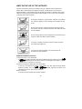
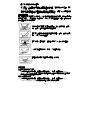
HINTS ON THE USE OF THE HOTPLATE
Utensils should always be placed centrally on the pan supports and over the burners.
Flames which extend beyond the bottom of utensils are wasteful and can damage or
overheat handles. Large diameter utensils (greater than 200mm in diameter) must not be
allowed to protrude beyond the perimeter of the hotplate, as this could cause overheating
or damage to the adjacent bench.
Do not place anything, e.g. flame tamer, asbestos mat, between
pan and pan support as serious damage to the appliances may
result.
Do not remove the pan support and enclose the burner with a
wok stand as this will concentrate the flame and deflect the heat
onto the hotplate.
Do not use large pots or heavy weights which can bend the pan
support or deflect the flame onto the hotplate.
Locate pan centrally over burner so that it is stable and does
not overhang the appliance.
Use only wok support supplied or recommended by the
manufacturer of the appliance.
Additional Installation Instruction
Connection of LPG or TG rubber tube
- It must be used approved rubber tube bearing EMSD Approval marking (such as
“機電
工程署批准
EMSD Approval GTXXXX”) and fuse cock for piped gas supply or cylinder
regulator for LPG cylinders for connection.
Connection of stainless steel flexible hose BSP MALE
- It must be used approved stainless steel flexible hole BSP MALE bearing EMSD
Approval marking (such as
“ 機電工程署批准 EMSD Approval GTXXXX”) and
approved fuse cock or gas cock for connection.
HKTG connection
- Governor: Beckley TG2355-00 should be installed.

9
SAFETY HINTS
Always turn pan handles to the side or back of the hotplate – not out into the kitchen where
they can easily be knocked.
Do not wear loose fitting garments while the burners are in operation, due to the possibility
of fabric ignition which may result in personal injury.
RECOGNIZING ABNORMAL OPERATION
In the event of any failure, before calling your service agent,
Please check the following:
NO IGNITION : Check if anything is obstructing the electrode metal tip.
NO GAS : Check that the gas is turned on at the mains meter.
BURNER FLAME NOT : Check the burner head is sitting evenly and that the slots in
BURNING EVENLY the burner head are not obstructed.
In the event that you are not satisfied with the hotplate, the distributor in your State should
be consulted.
IMPORTANT:
Under the Gas Safety (Registration of Gas Installers and Gas
Contractors) Regulations, only registered gas installers (registered to the
appropriate class) employed by registered gas contractors can personally
carry out gas installation work. “Gas Installation Work” includes the
fabrication, connection, or replacement of gas pipework, appliances and
fitting.
PLEASE NOTE
The hob is made of very resistant toughened glass and with proper handling stand up to all
household stresses. Before using the hob for the first time, please read the “Installation
and operating instructions” booklet carefully.
Do not use aluminum foil cover. Using aluminum foil cover may cause abnormal
combustion.
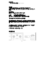
SAFETY DISTANCE

10
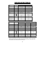
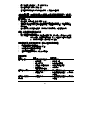
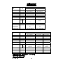
SPECIFICATION TABLES
Model number
Items
Unit
ER70762HK ER70962HK
Ignition -
DC 1.5V Battery DC 1.5V Battery
Top plate material
-
8mm toughened 8mm toughened
Glass colour -
Black Black
Glass shape -
Curved Sides Curved Sides
Burner Configuration -
2 3
Gas Type -
HK Town Gas HK Town Gas
Heat input for burner kW
(Mj/hr)
Left
Centre
Right
5.0 (18)
5.0 (18)
5.0 (18)
2.42 (8.7)
5.0 (18)
Flame failure device - Yes Yes
Inlet Governor
Test Point Pressure
Working Pressure
kPa 1.0 -----2.0
1.5
1.0
1.0 -----2.0
1.5
1.0
Gas inlet connection
-
Screw – 1/2 inch BSP Screw – 1/2 inch BSP
Model number
Items
Unit
ER70922HK ER70926HK ER70962HK
Ignition -
DC 1.5V Battery DC 1.5V Battery DC 1.5V Battery
Top plate material
-
8mm toughened 8mm toughened 8mm toughened
Glass colour -
White Black Black
Glass shape -
Curved Sides Curved Sides Curved Sides
Burner Configuration -
3
3 3
Gas Type -
LPG LPG LPG
Heat input for burner kW
(Mj/hr)
Left
Centre
Right
4.4 (15.84)
1.3 (4.68)
4.4 (15.84)
4.2 (15.00)
1.1 (3.8)
4.2 (15.00)
4.4 (15.84)
1.3 (4.68)
4.4 (15.84)
Flame failure device - Yes Yes Yes
Nominal Pressure kPa 2.9 2.9
2.9
Gas inlet connection
-
Screw – 1/2 inch BSP Screw – 1/2 inch BSP Screw – 1/2 inch BSP
Design and specification may change due to product improvement. No prior notice will be
given. If there are any queries, please feel free to contact our service center. Please refer
to the English version of this manual as the standards.

11
氣體嵌入式平面爐
雙頭氣體爐
ER70762HK 煤氣
三頭氣體爐
ER70962HK 煤氣
ER70926HK ER70922HK 石油氣

12
安裝及操作說明書
(06/2010)
目錄
安裝說明……….…………………………………………………14-15
維修說明……………………………………………………….…16
細火調節…………………………………………………….....16
故障檢索表…………………………….…………….…….…..16
操作說明……………………………………….…….……………17
爐具使用要訣……………………………………………….….18
識別異常操作…………………………………………………..19
產品資料表………………………….……………………….…....20

13
前言
必須按照製造商的說明、相關的氣體安裝規定、認可的燃氣爐具安裝指引及
其它法例和守則。
初次使用之前應詳細閱讀本說明,並妥善保管,以便充分利用嵌入式平面爐的
功能。
注意:
根據香港法例第 51 章氣體安全規定,任何氣體配件(包括接駁軟喉)的安裝/更換必
須由香港政府註冊氣體工程承辦商僱用的註冊氣體裝置技工負責,否則即屬違法。

14
G6001
安裝說明
資料標示詳情:
資料標識位於承液盤的前方。
首先檢查資料標識,查看本爐具是否適合使用現時的氣體供應。
1. 安裝本爐具前,檢查確保安裝位置要遠離易燃材料,必要時,按法例規定要求
對爐具周圍提供保護措施。將氣體供氣連接於圖 A 所示的進氣口。
2. 將檯面切成圖 B 所示的尺寸。
3. 從紙盒中取出爐具。
Models: ER70762HK
Models: ER70962HK / ER70926HK / ER70922HK
如果側面及後面的牆壁離爐具外圍不足 150 毫米,必須用非易燃材料保護牆壁。
Gas inlet
Gas inlet

15
保護物必須伸延離爐頭之上至少應達到 450 毫米,爐頭上方垂直距離不足 750 毫
米的水平表面也必須加以保護。
4. 在開孔處安裝爐具 (參見圖 B)
5. 至調節器的連接時,氣體管接頭為英制½吋螺紋外牙氣體爐入氣咀管口。應使
用扳手擰住調節器的預設平面位置。開啟氣體開關,在接頭和接口周圍塗上肥
皂溶液檢查是否漏氣。
壓力測試點:
- 氣體調節器中有壓力測試點
- 取下螺絲,連接壓力錶的軟管
- 開啟至猛火爐頭的氣體開關,手動點燃爐頭
- 在資料標示上標有壓力
- 如要增加壓力時,鬆動鎖緊螺絲母,按順時針方向旋轉
- 拆開壓力錶,擰回測試點螺絲
6. 本爐具的測試:
- 按下控制旋鈕,旋轉至最大火燄
- 爐頭將點火,將控制旋鈕調整至所需的設定。一般無需調整。
- 如果出現問題,請參閱維修說明或故障檢索表。
7. 確保用戶留有使用說明書。
如果上述任何程序結果不滿意,應向代理商之維修部查詢,尋求專業協助。
8. 本爐具配有火焰熄滅關氣裝置。爐頭火焰突然熄滅或者燃燒不正常時,該安全
裝置自動切斷燃氣供應,避免發生漏氣事故。
9. 室內通風
爐具必須安裝於設有永久通風裝置的室內,從而提供適當的流通空氣。位於室
內的永久通風口不能少於 100 平方厘米,及流通空氣不能少於 20 立方米。通風
口必須沒有任何阻塞。在乎合當地有關煙氣排出室外的規例下,流通空氣亦可
間接從相連房間進入。
警告:
- 爐具在使用的過程中,請勿在附近噴氣溶膠。
- 在高溫時,有些壓縮燃氣會發生化學變化,產生一些侵蝕某些材料的腐蝕性氣
化體。
- 本爐具下的抽屜或廚櫃中,不得存放易燃材料製成的物件。
- 在任何情況下,不得取下硅橡膠墊圈。如有任何保護性橡膠墊圈脫落或損壞,
用戶應停止使用本爐具,等待適當維修之後再行使用。

16
- 請勿在爐具外殼底部的 50 毫米內存放物件。
- 點燃爐頭時請勿觸摸火花點火器。
- 當本爐具安裝在船隻上或移動住所中時,不得當作暖爐使用。
維修說明 (所有程序必須由合格氣體裝置技工進行)
細火調節
細火調較螺絲入口
- 點燃爐頭,旋轉至最小設定 (標有小火燄)
- 在最小設定,火燄應該穩定,當從最高設定調到較低設定時,火焰不應熄滅。
- 如果有必要調整,向上拉動取出控制旋鈕,拆出爐頭及承液盤,將爐頭玻璃面
提起拆出。
- 細火調較螺絲就在控制鈕軸旁。按逆時針方向旋轉螺絲,增加調節比率。
歧管、氣體爐頭和爐頭組件入口
- 取下玻璃爐面和控制旋鈕。
- 拆下氣體塞: 鬆動鎖緊螺母 (在氣塞與爐頭之間),取下螺絲,現在可以從歧管
上取下氣塞。如果需要接觸筒管,取下將軸固定於爐具的兩個螺
絲。潤滑機械裝置時,請使用認可的油脂。
更換電極方法 (進行本程序之前,請先將爐具與電源隔離)
1. 取下玻璃爐面及控制旋鈕
2. 將電極引線從火花控制盒插座上拔出
3. 拆掉圍繞瓷質電極體的彈簧圈
4. 從支座上拆出電極
5. 組裝:電極組裝步驟與上述拆除步驟相反
故障檢索表
故障 原因 解決方法
爐頭點不著火
1. 氣體管道中有空氣
2. 管道堵塞
3. 點火無火花
4. 防漏熄火裝置有故障
5. 檢查電池
(適用於配有電池型號)
1. 吹掃管道
2. 查找和清理
3. 檢查導線和電極
4. 更換熱電偶並測試
5. 更換電池
爐頭點燃至噴嘴 1. 爐頭混合管毛絨過多
2. 氣體壓力過大
1. 取下爐頭進行清潔
2. 檢查氣體調節器壓力,必要時予
以調整。
爐頭點火時帶有
爆炸聲
1. 氣體壓力過大 1. 檢查氣體調節器壓力,必要時予
以調整。

17
點火器無火花 1. 電極隙過大
2. 點火器接頭
1. 檢查電極隙,如果未處於 4-5 毫
米之間,請調整。
2. 檢查點火器的接頭,如有故障時
需更換。
如有任何問題無法解決,請與本地的代理或氣體供應商之維修部聯絡。
操作說明
在爐頭的設計和外形方面具有獨到之處,雙頭爐安裝有兩個猛火力爐頭,而三頭爐
除了安裝有兩個同類爐頭外,還有一個煮沸水爐頭。這些爐頭都適宜一般煮食,但
是兩個猛火力爐頭經過專門設計,用於中式鑊猛火煮食,與普通的爐頭相比,火燄
熱量和覆蓋面多一倍半。
爐頭均帶有普通文火烹飪裝置。中式鑊爐頭可放置大鑊。
點火
此爐具的每個爐頭均配有電子點火設備,通過按壓單個控制旋鈕,按逆時針方向轉
¼周進行操作。
控制器
此爐具的每個爐頭都有獨立控制旋鈕,位於玻璃面的前方,指示符號可以顯示哪個
旋鈕控制哪個爐頭。在每個爐頭控制旋鈕旁的玻璃面上有大小火燄圖,表示 FULL-
ON (大火)和預設的“文火"位置。
爐頭的操作
1. 按下需要的控制旋鈕,按逆時針方向轉至 FULL-ON (大火) 位置。
2. 爐頭點火後,將控制旋鈕調整至需要的設定。按逆時針方向再旋轉旋鈕至預設
的“文火"位置,即可以調整火燄大小。
更換電池 (適用於電池點火型號)
1. 打開電池盒蓋
2. 取出舊電池
3. 放入新 1.5 伏特“D"型電池
4. 關上電池盒蓋
清潔
- 等待爐具冷卻後再自行拆卸或清潔。用一塊布以暖肥皂水清潔玻璃面,則效果
最佳。盡量避免使用洗潔粉及洗潔劑,但必要時請用柔性洗潔材料。為了去除
頑固的油脂,可以使用塗上肥皂水的鋼絨刷。
- 高濃度鹼溶液、洗滌鹼、氣溶膠噴劑、漂白劑和某些生化清潔劑,對某些表面
有損害,應小心處理,不得將其塗在爐具和爐頭上。

18
- 請勿在洗碗碟機中洗滌爐頭。
- 為了便於清潔,盡可能早點除去爐碟的湯料和食物。控制旋鈕可以拉出,便於
清潔下面,但是要小心勿使水進入玻璃面上的孔中。
- 當重新放回爐碟時,一定要確保將其放在火花電極之上。應該小心使電極保持
清潔,在清洗過程中取下爐碟時避免損壞塘瓷絕緣體。
爐具使用要訣
烹飪器皿應該放在爐頭之上的中央,火燄超過器皿底部會造成浪費,有可能損壞手
柄或使之過熱。大口徑器皿 (口徑超過 200 毫米) 不得突出爐面的外圍,否則可能使
附近櫃面過熱或造成損壞。
在鑊和爐架之間請勿放置任何東西,如火燄撲滅器、石棉毯
等,否則,會對本爐具造成嚴重損壞。
請勿取下爐架及用鑊架圈在爐頭的周圍,否則,會使火燄聚
中,將熱力反射到爐面上。
請勿使用大壺或重物,爐架會變彎或將火燄反射到爐面上。
將鑊放在爐頭的中央,放穩,勿使爐具過偏。
請僅使用供應的本爐具製造商推介的鑊架。
安裝說明
石油氣或煤氣膠喉之接駁
- 必須使用合格印有機電工程署批准標記(例如,“機電工程署批准 EMSD
Approval GTXXXX" 字樣) 之膠喉及供應管道式石油氣或煤氣使用的溢流掣或
瓶裝石油氣使用調壓器進行接駁。
煤氣不銹鋼軟喉接駁
- 必須使用合格印有機電工程署批准標記(例如,“機電工程署批准 EMSD
Approval GTXXXX") 之不銹鋼軟喉及溢流掣或氣掣進行接駁。

19
香港煤氣接駁
- 接駁煤氣時須加上穩壓器 Beckley TG2355-00
安全提要
將鑊柄轉到側面或爐具的背面,而不是朝向在廚戶易於碰撞到的方向。
在爐頭的使用過程中,請勿穿戴寬鬆衣服,因為織物為易燃物品,可能造成個人身
體傷害。
識別異常操作
出現故障,致電給維修代理之前,請檢查下列各項:
不能點火 :檢查是否有東西堵塞電極金屬尖。
無氣體 :檢查主氣體表處的氣體開關是否打開
爐火燃燒不勻:檢查爐頭是否放置平穩,爐頭中的槽口未被堵塞。
如果您對爐具效果不滿意,請到本地的經銷商處諮詢。
注意:
根據香港法例第 51 章氣體安全規定,任何氣體配件(包括接駁軟喉)的安裝/更
換必須由香港政府註冊氣體工程承辦商僱用的註冊氣體裝置技工負責,否則即屬違
法。
您的爐具是由強化玻璃造成,在正常使用下,非常堅固耐用。在第一次使用爐具之
前,請閱讀「安裝及操作說明書」內之操作建議。
不要使用錫紙碟,錫紙碟可引致爐火不正常。
安全距離尺寸圖

20
產品資料表
Model number
Items
Unit
ER70762HK ER70962HK
Ignition -
DC 1.5V Battery DC 1.5V Battery
Top plate material
- 8mm toughened 8mm toughened
Glass colour - Black Black
Glass shape - Curved Sides Curved Sides
Burner Configuration - 2 3
Gas Type -
HK Town Gas HK Town Gas
Heat input for burner kW
(Mj/hr)
Left
Centre
Right
5.0 (18)
5.0 (18)
5.0 (18)
2.42 (8.7)
5.0 (18)
Flame failure device - Yes Yes
Inlet Governor
Test Point Pressure
Working Pressure
kPa 1.0 -----2.0
1.5
1.0
1.0 -----2.0
1.5
1.0
Gas inlet connection
-
Screw – 1/2 inch BSP Screw – 1/2 inch BSP
Model number
Items
Unit
ER70922HK ER70926HK ER70962HK
Ignition -
DC 1.5V Battery DC 1.5V Battery DC 1.5V Battery
Top plate material
- 8mm toughened 8mm toughened 8mm toughened
Glass colour - White Black Black
Glass shape - Curved Sides Curved Sides Curved Sides
Burner Configuration - 3 3 3
Gas Type -
LPG LPG LPG
Heat input for burner kW
(Mj/hr)
Left
Centre
Right
4.4 (15.84)
1.3 (4.68)
4.4 (15.84)
4.2 (15.00)
1.1 (3.8)
4.2 (15.00)
4.4 (15.84)
1.3 (4.68)
4.4 (15.84)
Flame failure device - Yes Yes Yes
Nominal Pressure kPa 2.9 2.9
2.9
Gas inlet connection
-
Screw – 1/2 inch BSP Screw – 1/2 inch BSP Screw – 1/2 inch BSP
本爐具在不斷改進中,如功能有所更改,恕不另行通知。
如有疑問,請與維修中心聯絡。
說明書內容以英文版本為準。
-
 1
1
-
 2
2
-
 3
3
-
 4
4
-
 5
5
-
 6
6
-
 7
7
-
 8
8
-
 9
9
-
 10
10
-
 11
11
-
 12
12
-
 13
13
-
 14
14
-
 15
15
-
 16
16
-
 17
17
-
 18
18
-
 19
19
-
 20
20


Siemens ER70962HK/01 ユーザーマニュアル
- タイプ
- ユーザーマニュアル
- このマニュアルも適しています
他の言語で
- English: Siemens ER70962HK/01 User manual
関連論文
その他のドキュメント
-
ROSIERES RVG2TG Installation Instructions Manual
-
Fisher & Paykel FISHER PAYKEL CG752DLPGB1 Gas on Glass Cooktop ユーザーガイド
-
Miele 6792870 取扱説明書
-
Ariston PH 741 RQO GH CN Operating Instructions Manual
-
Bosch PPW916B2TT/01 ユーザーマニュアル
-
-
-
Groupe Brandt DPG7341B 取扱説明書
-
Fisher & Paykel CG301D インストールガイド
-
Fisher & Paykel CG905DLPX1 ユーザーガイド