
- 1 -
中文说明书 ........................................................................................................................ 1-8
English User Manual ......................................................................................................... 9-14
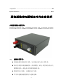
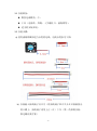
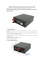
通信版数控电源钣金外壳安装说明
外壳适用数控电源型号:
DPS5015(DPS5015-USB)、DPS5020(DPS5020-USB)、DPS3012、DPH3205
一、 安装注意事项:
⚫ 安装前请仔细阅读本文档,如有疑问请与本公司联系。
⚫ 本外壳采用冷轧钢板材料,表面喷塑,安装、使用时应防止尖
锐物体划伤,避免阳光直晒和潮湿环境。
⚫ 组装时防止短路,正确连接正负极。
⚫ 不可在电源接通的情况下连接电路。

- 2 -
⚫ 尽量避免震动和跌落。
二、 产品规格
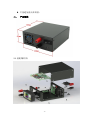
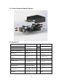
2.1 装配爆炸图:

- 3 -
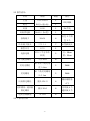
2.2 器件清单:
名称
规格
数量
备注
上盖
137*123*51
MM(长*宽*高)
1
冷轧钢板
底壳
1
风扇
4010
1
5V 供电
风扇供电板
36*40(长*宽)
1
接线端子
M4*36
4
红色 2 个黑
色 2 个
冷压端子接头
UT2.5-4
7
U 型插接头
船型开关
KCD3
1
连接电线
RV2.5 平方单芯
软线
2
红:30cm
黑:25cm
外壳配套螺丝
平头 M3*5
8
尼龙支撑柱
M3 单头六角尼龙
柱 L=8mm
2
PA66
尼龙螺母
M3 六角尼龙螺母
H=2.4mm
2
PA66
风扇固定螺栓
圆头 M3*13
4
螺丝螺帽各
4 个
功率模块、通信板
固定螺丝
圆头 M3*5
6
功率板 4 个
通信板 2 个
透明自粘脚垫
Φ12*4
4
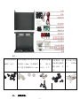
2.3 产品零件图:

- 4 -
备注:
外壳配套螺丝
M3*5 8 个
尼龙支撑柱 M3 单头六角
尼龙柱 L=8mm、尼龙螺母
M3 六角尼龙螺母 H=2.4mm
风 扇 固 定 螺
栓 圆头
M3*13 4 个
功率模块、通
信板固定螺丝
圆头 M3*5 共
6 个
冷 压 端 子 接
头 UT1-4
7 个
三、 安装步骤:

- 5 -
3.1 安装准备:
⚫ 数控电源模块一个。
⚫ 工具(电烙铁、焊锡、十字螺丝刀、剥线钳等)。
⚫ 适当的安装环境。
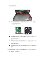
3.2 安装步骤:
a) 使用剥线钳截取适当长度的电线,电线长度参考下图:
b) 安装输入接线端子及开关(将接线端子和开关卡在后面板留出
的卡槽上,接线端子采用上正(红)下负(黑)的原则安装,
固定螺丝要拧紧)

- 6 -
c) 安装风扇供电板:
⚫ 将风扇电源线焊接到风扇供电板正面左下方的 5V 焊盘上
(注意正负极不要焊反)。
⚫ 将电源输入线焊接在风扇供电板左上角的两个焊盘上,(注
意正负极不要焊反)。
⚫ 将供电板安装在后面板的接线端子上(注意正负接口),然
后使用螺母固定。
⚫ 将电源开关用预先准备好的连接线焊接在供电板 Key 处焊
盘上。
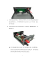
d) 安装散热风扇(注意采用配套的螺栓固定,风扇贴有指示标签
的一侧朝外,不可装反)

- 7 -
e) 安装好输出接线端子,将准备好的带有冷压端子的输出线连接到
输出接线端子上,并用螺母拧紧(输出端子上正下负安装,输出
线不要接错)
f) 本外壳针对的产品分为显示部分、功率部分、USB 通信部分,安
装过程为:
⚫ 首先安装通信部分(如果产品不附带通信功能,本步骤忽略),
使用尼龙支撑柱和尼龙螺母把通信板支撑起来,然后使用通
信板固定螺丝将其固定在底壳预定位置上

- 8 -
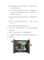
⚫ 安装显示模块将其卡入前面板卡槽上(卡入过程用力要适当,
防止造成前面板变形)。
⚫ 安装上显示模块和功率模块连接的排线,注意 PCB 板的丝印
层 LCD 和 KEY 排线插接的位置(排线一定走 PCB 板的下方,
否则电感会对其有干扰)。
⚫ 根据下盖板四个孔的位置安装功率模块,使用配套螺丝将其
固定住。
⚫ 将输入正负分别接到功率模块的 IN+,IN-;输出正负接到
OUT+,OUT-。
⚫ 通过通信板连接线连接通信板与功率板
g) 连接好之后可以通电看是否连接成功。(注意通电前再次检查接
线是否正确)
h) 安装上盖,将上盖装配到下壳,采用配套螺丝固定
i) 本产品配套四个透明脚垫,用户可对称粘贴到外壳底部四个角上。
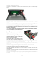
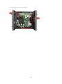
3.3 内部连线图:

- 9 -
Digital Control Power Supply Housing Installation Instructions
This housing is suitable for the following mode of digital control power supply:
DPS5015(DPS5015-USB-BT)、 DPS5020(DPS5020-USB-BT)、 DPH5005(DPH5005-USB-BT)、
DPS3012、DPH3205
1. Installation Note:
1.1 Please read the instructions carefully before installation. If you have any question, please
contact us.
1.2 This housing adopts cold-rolled steel sheet material, so please avoid being scratched by sharp
objects, direct sunlight and humid environment.
1.3 when install this, please avoid short-circuit and connect positive and negative
electrode correctly
1.4 Forbid connect the circuit after power on.
1.5 Please avoid vibration and fall.
2. Product Specifications

- 10 -
2.1 Product Assembly Explode Diagram
2.2 Kit parts list
Item
Specification
Qty.
Remark
Upper cover plate
137*123*51
MM(L*W*H)
1
Cold-Roll Steel Sheets
Lower cover plate
1
Fan
4010
1
5V power supply
Fan power supply board
36*40(L*W)
1
Binding post
M4*36
4
Red 2pcs
Black 2pcs
Cold press connecting
terminal
UT2.5-4
7
Spade Terminal
Rocker Switch
KCD3
1
Connecting line
RV 2.5 square single
core flexible cord
2
Red 30cm
Black 25cm
Screw for housing
Flat head M3*5
8
Fan fixed screw
Fillister head M3*13
4
Screw 4 pcs
Nut 4 pcs
Nylon column
M3 Single head hex
nylon column L=8mm
2
PA66
Nylon Nut
M3 hexagonal nylon nut
H=2.4mm
2
PA66

- 11 -
Power module and
communication board fixing
screw
Fillister head M3*5
6
Transparent sticky mat
Φ12*4
4
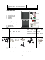
2.3 Kit Parts Picture
1- Lower cover plate
2- Fan
3- Connecting line
4- Transparent sticky mat
5- Fan power supply board
6- Rocker Switch
7- Binding post
8- Power module and communication
board fixing screw
9- Cold press connecting terminal
10- Screw for housing
11- Nylon column 、 Nylon Nut
12- Fan fixed screw
13- Upper cover plate
Note:
Screw for housing
8pcs
Nylon column M3 Single head
hex nylon column L=8mm
2pcs 、 Nylon Nut M3
hexagonal nylon nut H=2.4mm
2pcs
Fan fixed screw
Fillister
head M3*13 4pcs
Power module and
communication board
fixing screw Fillister head
M3*5 6pcs
Cold press
connecting
terminal UT2.5-4
7pcs
3 Installation Procedures
3.1 Installation Preparation
3.1.1 1 pcs digital control power supply
3.1.2 Tools (Soldering iron, solder, Philips screwdriver, Wire stripping pliers)
3.1.3 A proper installation environment
3.2 Installation Procedures

- 12 -
3.2.1 Use wire stripping pliers to cut proper
length line, the length as follows:
14- Fan line 45mm
15- Switch connecting line 35mm
16- Output positive line 50mm
17- Output negative line 60mm
18- Input positive and negative connecting line
150-180mm
19- Output positive line 60mm
20- Output negative line 70mm
21- Input positive and negative connecting line
3.2.2 Install the input binding post and
switch: put binding post and switch on slot
at rear panel. Install binding post according
to rule that red is positive above, black is negative below; and screw it tightly.
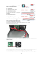
3,2.3 Install fan power supply board:
3.2.3.1 Weld fan line on 5V place at fan power supply board (Note: can’t weld positive and
negative reversely).
3.2.3.2 The power input line welding in the fan power supply board on the upper left corner of
the two pads, pay attention to the positive and negative do not welding the wrong.
3.2.3.3 Install fan power supply board on the binding post (red is positive above, black is negative

- 13 -
below), then use the screw to fix them.
3.2.3.4 Use the prepared wire to weld the power switch on the key place at fan power supply
board.
3.2.4 Install the fan: use the matched screw to fix. The one side attached label is installed
outward.
3.2.5 Install the output binding post, and use the output line with cold press connecting terminal
to connect input (red is positive above, black is negative below),and screw it tightly
3.2.6 Module connection using pluggable terminal, the input and output of the four threads into
the correct hole in the terminal, and tighten the screw (this process must pay attention to the
four lines do not get wrong)
3.2.7 This step contains power supply board installation, display part and USB board installation.
3.2.7.1 Firstly install USB communication board (if
you bought no communication version, please
ignore this step). Use nylon column and nylon nut
to prop USB board up. Then use the screw to fix it
on preset place of bottom housing
3.2.7.2 Install the display part. Please put it on slot
at front panel (when put it on slot, strength will be
proper to avoid the deformation).
3.2.7.3 Use the cable to connect display part with
power part. Note the words LCD and KEY on PCB
to correspond to the same words on display part (the cable must go through under the PCB,
otherwise the capacitor will generate interface to effect it).
3.2.7.4 According to the following four holes of the cover plate, mounted power module and use
screws to hold.
3.2.7.5 Connect input positive and negative to connect IN+ and IN-, and connect output.
3.2.7.6 use communication cable to connect USB board with module
3.2.8 After connecting, please power on to check it work or not (before power on, check
connection again)
3.2.9 Install the housing. The upper cover plate will be installed on the upper cover plate. And
then use the screw to fix them
3.2.10 There are 4 transparent sticky mat, you can paste symmetrically them on the 4 corners on
the bottom.

- 14 -
3.3 Internal connection diagram:
-
 1
1
-
 2
2
-
 3
3
-
 4
4
-
 5
5
-
 6
6
-
 7
7
-
 8
8
-
 9
9
-
 10
10
-
 11
11
-
 12
12
-
 13
13
-
 14
14


RD DPS5015-USB ユーザーマニュアル
- タイプ
- ユーザーマニュアル
- このマニュアルも適しています
他の言語で
- English: RD DPS5015-USB User manual
その他のドキュメント
-
Kyosho No.31255�@V-ONE RR EVOLUTION SERIES ユーザーマニュアル
-
-
Yamaha CDR-HD1500 ユーザーマニュアル
-
HPI Racing Jumpshot V2.0 ユーザーマニュアル
-
Hikoki C 12LSH ユーザーマニュアル
-
-
-
-
-
Siruba D007R Instruction book