CDR-HD1500
6
CDR-HD1500
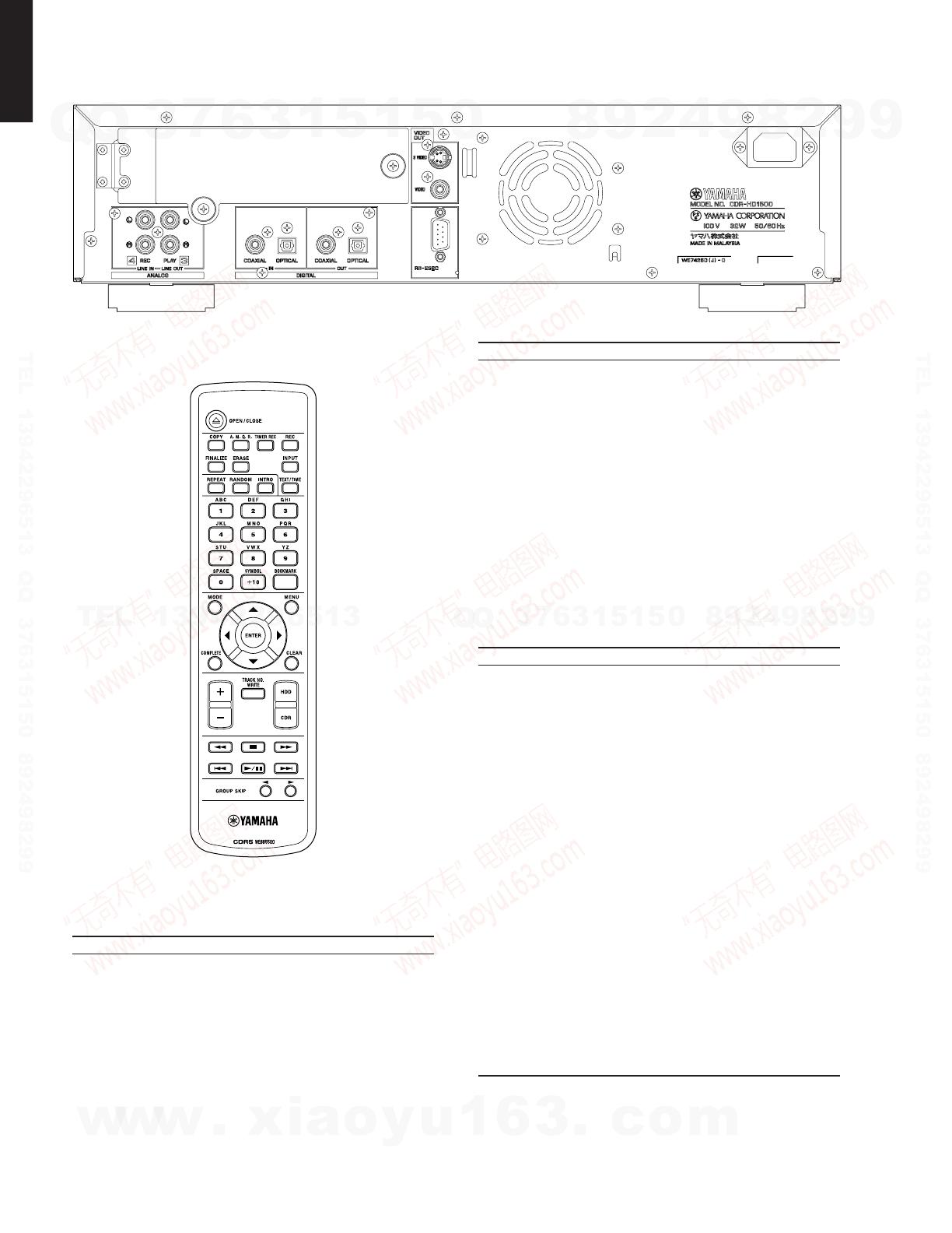
■ REMOTE CONTROL PANEL
CDR-HD1500 (J model)
■ SPECIFICATIONS /
AUDIO PERFORMANCE /
Output Level / (1kHz 0dB) ........................ 2 ± 0.5 Vrms
Frequency Characteristics / (EIAJ)
5Hz to 20kHz.................................................................... ± 0.5 dB
Playback Signal to Noise Ratio / (EIAJ)
...............................................................................105 dB or more
Playback Dynamic Range / (EIAJ)
.................................................................................99 dB or more
Playback THD + Noise / (EIAJ)
...............................................................................0.004 % or less
Recording Signal to Noise Ratio / (EIAJ)
.................................................................................92 dB or more
Recording Dynamic Range / (EIAJ)
.................................................................................92 dB or more
Recording THD + Noise / (EIAJ)
...............................................................................0.006 % or less
INPUT/OUTPUT /
Line Output /
Output Level ....................................................................... 2 Vrms
Output Resistance ......................................................... 990 ohms
Line Input /
Input Sensitivity ........................................................... 500 mVrms
Input Impedance .......................... 24 k-ohms (REC LEVEL Max.)
Digital Output /
Coaxial Output Level ..................................... 0.5 Vp-p (75 ohms)
Optical Output Level ........................................................ -20 dBm
Sampling Frequency ....................................................... 44.1 kHz
Digital Input /
Coaxial Input Level ........................................ 0.5 Vp-p (75 ohms)
Optical Input Level ........................................................... -20 dBm
Input Gain (with Digital Volume) ........................................ ±12 dB
Input Gain (without Digital Volume) ..................................... ±0 dB
Sampling Frequency Tolerance
........................................... 32 kHz, 44.1 kHz, 48 kHz and 96 kHz
Headphone Output / (Phones Level Max)
Output Level (-20 dB, 150 ohms load) ....................... 330 mVrms
GENERAL /
Model / HDD / CD recorder
Application Discs / CDs, CD-Rs for AUDIO, CD-
RWs for AUDIO
HDD Capacity / No HDD (Support BigDrive over
137GB, up to 400GB)
Power Supply /
U model ................................................................AC 120 V 60 Hz
A model ................................................................AC 240 V 50 Hz
B, G models .........................................................AC 230 V 50 Hz
J model ........................................................... AC 100 V 50/60 Hz
Power Consumption /
U, A, B, G models ................................................................. 37 W
J model .................................................................................. 32 W
Standby Power Consumption / 0 W
Operating Temperature / + 5 °C ~ + 35 °C
Max. Dimensions / (W x H x D)
.................. 435 x 115.5 x 414.5 mm (17-1/8" x 4-1/2" x 16-5/16")
(include legs, terminals and knobs)
Weight /
CDR-HD1500 without HDD ......................... 8.2 kg (18 lbs. 1 oz.)
Panel Color /
Gold Color ......................................................................... J model
Black Color ....................................................... U, A, B, G models
Titanium Color ............................................................ B, G models
Accessories
Remote Control x 1, Optical Cable x 1, Audio Pin Cable x 2,
Video Pin Cable x 1, Power Cable x 1 (U, J models), Batteries
(Manganese Dry) x 2
* Specifications are subject to change without notice due to product
improvements.
U .......... U.S.A. model A ...... Australian model
B .......... British model G ...... European model
J ........... Japanese model
http://www.xiaoyu163.com
http://www.xiaoyu163.com


