
Owner’s Manual
CP-700
Preamplifi er
用户手册
CP-700
前置放大器
中文
ENGLISH
驾势

2
ENGLISH
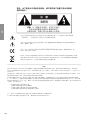
CAUTION
RISK OF ELECTRIC SHOCK
DO NOT OPEN
CAUTION:
TO REDUCE THE RISK OF ELECTRICAL SHOCK, DO NOT
REMOVE COVER. NO USER-SERVICEABLE PARTS INSIDE. REFER
SERVICING TO QUALIFIED PERSONNEL.
WARNING: TO REDUCE THE RISK OF FIRE OR ELECTRIC SHOCK, DO
NOT EXPOSE THIS APPLIANCE TO RAIN OR MOISTURE.
NOTICE
All of us at Classé take extreme care to ensure that your purchase will remain a prized investment. We are proud to
inform you that all Classé components have been of–cially approved for the European Community (CE) mark.
All of us at Classé take extreme care to ensure that your purchase will remain a prized investment. We are proud to
inform you that all Classé components have been of–cially approved for the European Community (CE) mark.
All of us at Classé take extreme care to ensure that your purchase will remain a prized investment. We are proud to
This means that your Classé product was subjected to the most rigorous manufacturing and safety tests in the world.
The CE mark certi–es that your purchase meets or exceeds all European Community requirements for unit-to-unit
This means that your Classé product was subjected to the most rigorous manufacturing and safety tests in the world.
The CE mark certi–es that your purchase meets or exceeds all European Community requirements for unit-to-unit
This means that your Classé product was subjected to the most rigorous manufacturing and safety tests in the world.
consistency and consumer safety.
The CE mark certi–es that your purchase meets or exceeds all European Community requirements for unit-to-unit
consistency and consumer safety.
The CE mark certi–es that your purchase meets or exceeds all European Community requirements for unit-to-unit
This equipment has been tested and found to comply with the limits for a Class B digital device, pursuant to Part 15
of the FCC Rules. These limits are designed to provide reasonable protection against harmful interference in a residen-
This equipment has been tested and found to comply with the limits for a Class B digital device, pursuant to Part 15
of the FCC Rules. These limits are designed to provide reasonable protection against harmful interference in a residen-
This equipment has been tested and found to comply with the limits for a Class B digital device, pursuant to Part 15
tial installation. This equipment generates, uses and can radiate radio frequency energy and, if not installed and used
of the FCC Rules. These limits are designed to provide reasonable protection against harmful interference in a residen-
tial installation. This equipment generates, uses and can radiate radio frequency energy and, if not installed and used
of the FCC Rules. These limits are designed to provide reasonable protection against harmful interference in a residen-
in accordance with the instructions, may cause harmful interference to radio communications. However, there is no
tial installation. This equipment generates, uses and can radiate radio frequency energy and, if not installed and used
in accordance with the instructions, may cause harmful interference to radio communications. However, there is no
tial installation. This equipment generates, uses and can radiate radio frequency energy and, if not installed and used
guarantee that interference will not occur in a particular installation. If this equipment does cause interference to radio
in accordance with the instructions, may cause harmful interference to radio communications. However, there is no
guarantee that interference will not occur in a particular installation. If this equipment does cause interference to radio
in accordance with the instructions, may cause harmful interference to radio communications. However, there is no
or television reception, which can be determined by turning the equipment on and off, the user is encouraged to try to
guarantee that interference will not occur in a particular installation. If this equipment does cause interference to radio
or television reception, which can be determined by turning the equipment on and off, the user is encouraged to try to
guarantee that interference will not occur in a particular installation. If this equipment does cause interference to radio
correct the interference by one or more of the following measures:
or television reception, which can be determined by turning the equipment on and off, the user is encouraged to try to
correct the interference by one or more of the following measures:
or television reception, which can be determined by turning the equipment on and off, the user is encouraged to try to
• Reorient or relocate the receiving antenna;
• Increase the separation between the equipment and the receiver;
• Reorient or relocate the receiving antenna;
• Increase the separation between the equipment and the receiver;
• Reorient or relocate the receiving antenna;
• Connect the equipment into an outlet on a circuit different from that to which the receiver is connected;
• Increase the separation between the equipment and the receiver;
• Connect the equipment into an outlet on a circuit different from that to which the receiver is connected;
• Increase the separation between the equipment and the receiver;
• Consult the dealer or an experienced radio/TV technician for help.
• Connect the equipment into an outlet on a circuit different from that to which the receiver is connected;
• Consult the dealer or an experienced radio/TV technician for help.
• Connect the equipment into an outlet on a circuit different from that to which the receiver is connected;
CAUTION: Changes or modi–cations to this equipment not expressly approved by the manufacturer could void the
user»s authority to operate the equipment.
CAUTION: Changes or modi–cations to this equipment not expressly approved by the manufacturer could void the
user»s authority to operate the equipment.
CAUTION: Changes or modi–cations to this equipment not expressly approved by the manufacturer could void the
The information contained in the manual is subject to change without notice. The most current version of this manual
will be posted on our web site at http://www.classeaudio.com.
The information contained in the manual is subject to change without notice. The most current version of this manual
will be posted on our web site at http://www.classeaudio.com.
The information contained in the manual is subject to change without notice. The most current version of this manual
The lightning —ash with arrowhead symbol, within an equilateral triangle, is intended to alert
the user to the presence of uninsulated dangerous voltage within the product»s enclosure that
may be of suf–cient magnitude to constitute a risk of electric shock to persons.
The exclamation point within an equilateral triangle is intended to alert the user to the
presence of important operating and maintenance (servicing) instructions in the literature
accompanying the appliance.
Marking by the ≈CE∆ symbol (shown left) indicates compliance of this device with the
EMC (Electromagnetic Compatibility) and LVD (Low Voltage Directive) standards of the
European Community.
Classe products are designed to comply with international directives on the Restriction
of Hazardous Substances (RoHS) in electrical and electronic equipment and the disposal
of Waste Electrical and Electronic Equipment (WEEE). The crossed wheelie bin symbol
indicates compliance and that the products must be appropriately recycled or processed in
accordance with these directives.

3
ENGLISH
Important Safety Instructions
Caution:
Please read and observe all warnings and instructions in this owner’s manual and all
those marked on the unit. Retain this owner’s manual for future reference.
1. Do not attempt to service this product yourself.
Do not open the cover for any reason. There are no
user-serviceable parts inside. An open unit, particularly if it is still connected to an AC source, presents
a potentially lethal shock hazard. Refer all questions to authorized service personnel only.
2. To prevent –re or shock hazard, do not expose the unit to water or moisture.
If a liquid does enter
your component, immediately disconnect it from the AC mains and take it to your Classé dealer for a
thorough check-up.
3. Do not place your component near any heat-producing device
such as a radiator, stove, etc., Keep
it away from direct sunlight.
4. Connect your component only to an AC source of the proper voltage.
The shipping container and
the rear panel serial number tag will indicate the proper voltage. Use of any other voltage may damage
the unit and void the warranty.
5. AC cords should be routed so that they are not likely to be walked on or pinched by items
placed upon or against them.
Do not stress the AC cord by stretching it to reach a plug. If damage
does occur to the AC cord, take it to your Classé dealer for a thorough check-up and proper repair or
replacement.
6. If your component will be out of use for an extended period of time
(vacation, etc.), you may wish
to unplug the power cord from the AC source to prevent any chance of problems from a voltage surge
or lightning strike.
7. NEVER
wet the inside of this product with any liquid.
7. NEVER wet the inside of this product with any liquid. 7. NEVER
8. NEVER
pour or spill liquids directly onto this unit.
8. NEVER pour or spill liquids directly onto this unit. 8. NEVER
9. NEVER
block air —ow through ventilation slots or heatsinks.
9. NEVER block air —ow through ventilation slots or heatsinks. 9. NEVER
10. NEVER
bypass any fuse.
10. NEVER bypass any fuse. 10. NEVER
11. NEVER
replace any fuse with a value or type other than that speci–ed.
11. NEVER replace any fuse with a value or type other than that speci–ed. 11. NEVER
12. NEVER
attempt to repair this product. If a problem occurs, contact your Classé dealer.
12. NEVER attempt to repair this product. If a problem occurs, contact your Classé dealer. 12. NEVER
13. NEVER
expose this product to extremely high or low temperatures.
13. NEVER expose this product to extremely high or low temperatures. 13. NEVER
14. NEVER
operate this product in an explosive atmosphere.
14. NEVER operate this product in an explosive atmosphere. 14. NEVER
15. ALWAYS
unplug sensitive electronic equipment during lightning storms.
Please record the serial number of your new Classé component here for future reference.
Serial #: __________________

4
ENGLISH
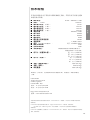
Contents
Welcome to the Classé family
.......................................................................
5
a word about installation
......................................................................
5
Unpacking and Placement
............................................................................
6
unpacking
your preamplifi er
................................................................
6
placement
...............................................................................................
6
ventilation
..............................................................................................
6
custom installations
...............................................................................
6
serial number
.........................................................................................
6
register your purchase!
.........................................................................
7
operating voltage
..................................................................................
7
warm up/break-in period
......................................................................
8
please read this manual…
.....................................................................
8
Special Design Features
.................................................................................
9
fl exible graphic
user interface
..............................................................
9
customizable
volume control
................................................................
9
highly refi ned
circuit design
.................................................................
9
extensive listening tests
.......................................................................
1
0
extraordinary longevity
.......................................................................
1
0
robust, isolated
power suppl
ies
..........................................................
1
0
Front Panel
...................................................................................................
1
1
Rear Panel
....................................................................................................
1
4
optional phono preamp
................................................................
1
4
The Remote Control
....................................................................................
1
9
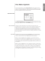
The Menu System
........................................................................................
2
1
operational menu
................................................................................
2
1
input selection
...............................................................................
2
1
tape loop
........................................................................................
2
1
main menu system
..............................................................................
2
2
system setup
.........................................................................................
2
2
volume
...........................................................................................
2
3
rotary
..............................................................................................
rotary ..............................................................................................rotary
2
3
max volume
...................................................................................
2
5
startup volume
..............................................................................
2
5
mute setup
.....................................................................................
2
6
input
...............................................................................................
input ...............................................................................................input
2
6
phono gain
....................................................................................
2
8
triggers
..........................................................................................
2
8
teach IR
.................................................................................................
2
8
display setup
........................................................................................
2
9
brightness
......................................................................................
2
9
timeout
..........................................................................................
timeout ..........................................................................................timeout
2
9
language
........................................................................................
3
0
main balance
........................................................................................
3
0
remote Fkeys
........................................................................................
3
0
cautionary note on Fkey use
.........................................................
3
1
status
....................................................................................................
3
2
version info
....................................................................................
3
2
sensors
............................................................................................
3
2
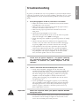
Troubleshooting
..........................................................................................
3
3
Care and Maintenance
................................................................................
3
6
cleaning the cabinet
............................................................................
3
6
cleaning the
LCD touchscreen
.............................................................
3
6
installing the
remote control batteries
..............................................
3
6
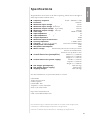
Specifi cations
...............................................................................................
3
7
Dimensions
...................................................................................................
3
8

5
ENGLISH
Welcome to the Classé family
Congratulations on your purchase of a Classé product. It is the result of many
years of continuous re–nement, and we are sure that you will enjoy it for many
years to come.
We value our relationship with our customers. Please allow us to stay in touch
with you by returning your warranty card now, before you pack up the shipping
carton of your new product and forget all about it. Doing so will enable us to
let you know about any possible future upgrades or updates that might become
available for your Classé component.
Sending in your warranty card also registers your product with us so that
warranty service can be obtained easily and quickly, even if you have mislaid
your original sales slip.
Please, take a few minutes to fi ll out the warranty
Please, take a few minutes to fi ll out the warranty
registration card, and drop it in the mail.
You will –nd the warranty registration card at the end of the separate warranty
policy booklet, enclosed.
a word about installation
Every effort has been made to make the Classé CP-700 simple and
straightforward to install and use.
Still, we have no way to evaluate many other variables such as the size and shape
of your room, its acoustics, and the associated equipment you have chosen to use
with your preampli–er. All of these factors in—uence the ultimate performance of
your system.
For this reason, we strongly encourage you to have your
For this reason, we strongly encourage you to have your
system installed and calibrated by your dealer, whose
experience, training, and specialized equipment can
make a profound difference in the fi nal performance of
the system.

6
ENGLISH
Unpacking and Placement
unpacking
your preamplifi er
Carefully unpack your preampli–er according to the supplied instructions, and
remove all accessories from the carton.
Important! Keep all packing materials for future transport of your
Important! Keep all packing materials for future transport of your
Classé product. Shipping your new component in anything
other than its purpose-designed packing material may
result in damage that is not covered by the warranty.
placement
As with any preampli–er, it is best to place the CP-700 centrally within your
system, since it is the hub to which all other components are connected. It
should also be located at a convenient height for both visibility and use, since
you generally interact with your preampli–er more than any other component
(changing inputs, adjusting volume, etc.).
Note that adequate clearance for the AC cord and connecting cables
must be left behind the CP-700. We suggest leaving eight inches (20
cm) of free space behind your preampli–er to allow all cables suf–cient
room to bend without crimping or undue strain.
Classé recommends that the unit not be placed directly on the top surface of a
power ampli–er (or any other heat source).
ventilation
Your Classé preampli–er generates a certain amount of heat in the course of
normal operation. Be sure to allow three inches of clearance above it and three
inches to each side to allow heat dissipation through air circulation. Avoid
placement on soft surfaces that would restrict air—ow (such as plush carpeting).
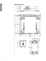
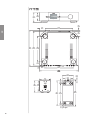
custom installations
Drawings are included in this manual to facilitate special installations and
custom cabinetry (see the section
Dimensions
). An optional, purpose-designed
Dimensions). An optional, purpose-designed Dimensions
rack mount kit is available for this product. Contact your Classé dealer for more
information.
serial number
The serial number for your preampli–er is found on the rear of the unit. Please
note and record this number on the page entitled
Important Safety Instructions
for your future reference.

7
ENGLISH
register your purchase!
Having found the serial number, now would be a good time to –ll out the
registration card. Please register your purchase so we can advise you of updates
and other items of interest.
It will take only a minute or so. Please complete the card now, before you forget.
operating voltage
The CP-700 preampli–er is set at the factory for 100V, 120V, 230V, or 240V
AC mains operation, as appropriate for the country in which it is to be sold
(230V only in European Union countries, in compliance with CE regulations)
. The
voltage setting may not be changed by the user.
Make sure that the label on the rear panel of your preampli–er indicates the
correct AC operating voltage for your location. Attempting to operate your
preampli–er at an incorrect voltage may damage the unit.
Warning: The voltage setting of your preamplifi er may not be
Warning: The voltage setting of your preamplifi er may not be
changed by the user. There are no user-serviceable parts
within the unit. Please refer any problems to an authorized
Classé service center.
If the AC mains voltage indicated on your preampli–er is incorrect, please
contact your local, authorized Classé dealer or distributor.
The CP-700 can easily be powered by a normal 15-ampere AC mains line. If
other devices are also powered from the same AC line, their additional power
consumption should be taken into account.
The CP-700 includes protection circuitry that will prevent the preampli–er from
operating at dangerously high or low voltages.
•
At startup:
the AC mains voltage must be within a range of
approximately -15% to +10% of its nominal value at startup,
or the preampli–er will not turn on. For example, a 120V unit
requires the AC mains to be between approximately 95V-135V in
order to turn on.
•
Over-voltage during operation:
if the AC mains voltage surges
by roughly 10% or more during operation, the preampli–er will
enter protection mode and shut down. The
Standby LED
will
—ash to indicate the protection mode has been engaged.
•
Under-voltage during operation:
if the AC mains voltage sags
by 15% or more, the preampli–er will continue to play (since
this does not present a particular danger to the ampli–er), but
note that it may not be able to achieve its usual standard of
performance under these compromised conditions. The
Standby
LED
will —ash to indicate the condition.

8
ENGLISH
warm up/break-in period
Your new Classé preampli–er will deliver outstanding performance immediately.
However, you should expect to hear it improve somewhat as it reaches its
normal operating temperatures and its various components ≈break-in.∆ It has
been our experience that the greatest changes occur within the –rst 300 hours, as
the preampli–er reaches thermal equilibrium and the capacitors fully form. After
this initial break-in period, the performance of your new product should remain
quite consistent for years to come.
The only exception to this rule is if the unit is unplugged for an extended period
of time, allowing it to cool down. Depending on the degree of cooling involved,
you should expect a brief warm-up period before the preampli–er»s sound
quality is at its best. Unless your preampli–er was allowed to become quite
chilled, subsequent thermal re-stabilization should not take long. Fortunately,
you should never have to repeat the initial 300 hour break-in period.
please read this manual…
Please take a few minutes to review this manual, and to familiarize yourself with
your new preampli–er. We understand that you are anxious to plug everything
in and get started. However, reading this manual and following the advice it
gives will ensure that you get all the bene–ts you deserve from having purchased
such a –ne piece of equipment .

9
ENGLISH
Special Design Features
fl exible graphic
user interface
The LCD touchscreen on the front panel of your new component supports an
extremely —exible and versatile graphic user interface (GUI) while maintaining
a clean, uncluttered appearance. The CP-700 provides a range of controls
that might otherwise require dozens of buttons and knobs on the front panel.
Despite this power and —exibility, it remains simple to operate in day-to-day use.
In fact, in some ways it is even simpler to operate than a more conventional
design might be. For example, if you are not using one or more of the inputs
on your CP-700, you can delete the unnecessary buttons from the operational
menu. Doing so prevents anyone from trying to select a non-existent source
component, with the resulting confusion stemming from the lack of any sound.
(Of course, you can easily restore the button if you subsequently add another source
component and need that input.)
customizable
volume control
The volume control on your new Classé preampli–er is controlled by
sophisticated software that allows you to –ne-tune its response to suit your
preferences.
Ideally, a volume control would allow you to reach the volume you desire
quickly, and would also provide extremely –ne control once you are close to the
≈perfect∆ volume. Of course, these characteristics are in con—ict with each other:
one requires the volume to change by quite a lot for a given amount of turning
of the knob, while the other requires small, incremental changes for the same
turn of the knob.
The volume control system on your CP-700 solves this problem by responding
differently based on the speci–c circumstances (e.g. how quickly you are turning
the knob and where in the volume range you are). After extensive testing, we
feel we have created factory default settings that most people will –nd intuitive
and a real pleasure to use. However, if you feel you would like to –ne-tune its
performance further in order to suit your particular preference, you may easily
do so.
highly refi ned
circuit design
All Classé analog ampli–cation stages are based on circuits that have been
extensively optimized over many years of continuous development.
By starting with excellent circuit designs and working with them over the years,
we are able to discover the many small re–nements that add up to superlative
performance, in a variety of applications. Altering a voltage here, or using a
slightly different part there, may make all the difference between solid and
absolutely outstanding performance.
This level of re–nement only comes with a great deal of experience, and is
not available to those who —it from one trendy notion to the next. It accounts
in no small measure for both the consistency of sonic performance among
Classé products (as they are all based on similar analog gain stages), and for the
consistently excellent reviews these products receive from owners and reviewers
alike.

10
ENGLISH
extensive listening tests
Excellent measured performance is to be expected in world-class products, and
Classé products deliver that performance. However, experience has shown that
technical excellence alone is insuf–cient to guarantee subjectively musical results.
For this reason, all Classé products are laboriously –ne-tuned during the
development process by carefully controlled listening tests. Our ears are still
some of the –nest laboratory test instruments available, and nicely complement
more traditional engineering test equipment. In the course of optimizing the
circuitry for a product, hundreds of decisions are made based on the subjective
impression given by substituting one high quality part for another.
As an example, we may listen to half a dozen 0.1% tolerance –lm resistor
components of the same value, from several different companies. Standard tests
may show them all to provide identical results in terms of noise, distortion, and
so forth. Yet, almost invariably, one selection yields some small improvement in
the subjective reaction to the performance of the product under development.
Less often, even a single such change can result in a surprisingly large
improvement.
Multiply those various improvements by the dozens or even hundreds of such
decisions that must be made before the product can be –nalized for production,
and you have a remarkable improvement, indeed – all based on careful listening
tests, which we view as a necessary complement to the solid engineering you
might rightly expect from Classé.
extraordinary longevity
Another bene–t of having worked with highly re–ned circuit designs so
extensively over many years is that we have vast experience in what works well
over the long term.
By using only the highest quality parts to begin with, and then using them in an
informed way as a result of both accelerated aging experiments and actual long-
term experience, we are able to design and manufacture products which we are
con–dent will stand the test of time.
We are con–dent that your new Classé preampli–er will give you many years of
trouble-free reliability and musical enjoyment, just as previous Classé products
have given their owners.
robust, isolated
power supplies
The CP-700 employs an outboard power supply to provide the ultimate in
performance. This unit includes a massive 135 VA toroidal transformer with
–ve secondary windings to provide maximum isolation for both the positive
and negative voltages required by each channel, as well as the voltage used by the
control circuitry within the preampli–er itself.
This design approach ensures that the preampli–er itself sees only the pure,
highly-regulated DC power it needs for handling the music signals, while the
high-voltage AC mains is kept safely away from your music. In short, it creates
an ideal environment in which the re–ned circuitry of the CP-700 can operate
to its full potential in service of your musical enjoyment.

11
ENGLISH
MENU
CP-700
MUTE
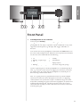
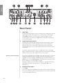
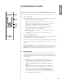
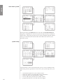
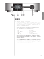
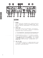
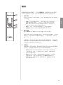
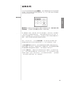
Front Panel
1 Standby button & LED indicator
The front panel
Standby
button will toggle the preampli–er between
Standby button will toggle the preampli–er between Standby
operate
, its fully operational state, and a
operate, its fully operational state, and a operate
standby
mode that leaves the
standby mode that leaves the standby
preampli–er off, yet ready to respond to system commands via any of the
supported control options (e.g. IR input, DC trigger, CAN Bus, or
RS-232).
The current state of the preampli–er is indicated by the
LED
indicator in
the center of the standby button. When the unit is powered and switched
on, the state of this LED indicates the following:
• on =
standby
• —ashing
(on power-up)
=
(on power-up) = (on power-up)
initialization
• off =
operate
• on
(dim)
=
(dim) = (dim)
display timeout
• —ashing
(after power-up)
=
(after power-up) = (after power-up)
AC mains voltage out of range
If you are planning not to use the preampli–er for an extended period of
time, e.g. vacation or other travel, we suggest you disconnect it from the
AC mains. Please be certain that the preampli–er is turned off prior to
disconnecting it from the AC mains.
Also, it is a good practice to physically disconnect any and all valuable
electronics from the AC mains during electrical storms, as a lightning
strike anywhere near your home can put a tremendous surge on the AC
mains that can damage any piece of electronic equipment, no matter how
well designed and protected. The best protection in the case of severe
electrical storms is simply to remove the electronics from any connection
with the power grid.

12
ENGLISH
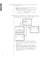
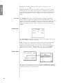
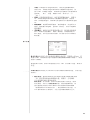
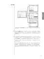
2 Menu button
Pressing the front panel
Menu
button will call up the
main menu system
,
replacing the normal operational menu and status display in the LCD
touchscreen.
3 LCD touchscreen
Much of your interaction with the CP-700 will be via the
LCD
touchscreen
(and the CP-700»s supplied remote control). It will usually
display the various
input selection
buttons you would use in day-to-day
operation, along with access to the tape button.
By pressing the
Menu
button, you can also call up the
menu system
of the
menu system of the menu system
CP-700, which gives you control over many of the operational details of
the preampli–er, including
system setup
options, various
system setup options, various system setup
display
options
display options display
(including the
language
in which the menu system itself displays), and
language in which the menu system itself displays), and language
several custom-installation capabilities that allow superior integration of
the CP-700 into complex systems.
For more information, see the section
The Menu System
later in this
The Menu System later in this The Menu System
manual.
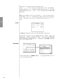
4 Mute button
The front panel
Mute
button reduces the volume of the preampli–er to
zero at the touch of a button. Pressing the button a second time restores
the volume to its previous setting. The behavior of the mute can also be
customized. Setup information on this feature is available in the
Volume
Setup
section.
Setup section.Setup
However, if you increase the volume manually (using either the
volume
knob
or the
remote control
) while the
Mute
button is engaged, the mute
control will disengage and the volume will be set to zero. This approach
is a safety measure, to avoid situations in which the volume might be
adjusted up while muted, only to then have the system un-muted to an
unexpectedly high volume.
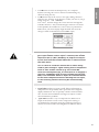
5 IR window
The
infrared
(IR)
infrared (IR) infrared
receiver
and
receiver and receiver
transmitter
are located behind this
transmitter are located behind this transmitter
window. Ordinarily, your Classé CP-700 must be able to ≈see∆ the
remote control from this window in order to respond to remote control
commands.
If your preampli–er will be located behind closed doors, or for any
other reason will not be able to ≈see∆ the remote control during normal
operation, you may use the rear panel
IR input
and
IR input and IR input
output
mini-jacks and
output mini-jacks and output
an
IR repeater system
to solve the problem. For more information about
IR repeater system to solve the problem. For more information about IR repeater system
using an infrared repeater system to route signals to and from the CP-700,
refer to the section
Rear Panel
later in this manual, or contact your local
Rear Panel later in this manual, or contact your local Rear Panel
Classé dealer.

13
ENGLISH
In addition to receiving IR commands, the CP-700 can also transmit IR
commands so they may be learned by third-party learning remote controls.
The CP-700 includes a comprehensive list of discrete IR commands to
facilitate the creation of reliable macros. Speci–cally, there are discrete
codes for all commands that normally operate as toggle functions (e.g.
separate
operate
and
operate and operate
standby
commands in addition to the normal
standby commands in addition to the normal standby
command that toggles between the two states).
6 Volume Knob
The large
knob
on the right side of the front panel of the CP-700 is used
to control the volume of the system.
The volume is raised or lowered in precise 0.5dB increments throughout
the range of the control most likely to be used while listening to music.
At extremely low volumes, the step size is increased somewhat to make it
easier to move quickly between extremely low and normal listening levels.

14
ENGLISH
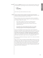
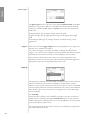
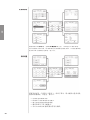
Rear Panel
1 Tape Input
Connect the analog outputs of any recording device (analog tape recorder,
digital tape recorder, CD recorder, etc.) you may have to these single-
ended
RCA
connectors. You may select to hear the output of your
RCA connectors. You may select to hear the output of your RCA
recording device by touching the
tape
button on the main operational
screen of the CP-700.
2 Single-ended (RCA) inputs
These RCA jacks accept right-channel and left-channel (single-ended)
inputs from line-level source equipment such as tuners, CD players,
and tape decks. Any of these inputs may be selected by touching the
corresponding button on the main operational screen of the front panel
touchscreen.
To achieve the best possible results, we suggest that you use only high-
quality, shielded interconnect cables. Please consult with your local Classé
dealer for advice on the best cables for use in your system.
optional phono preamp
If you have a turntable you would like to use with the system, an optional
phono preampli–er module is available from your Classé dealer. Once
installed in your preampli–er, the
Line 1
input connectors become your
phono
inputs, and the
phono gain
control in the menu system becomes
active, allowing you to select either
low gain
for all moving-magnet (MM)
low gain for all moving-magnet (MM) low gain
and high-output moving-coil (MC) cartridges, or
high gain
for standard
high gain for standard high gain
output MC cartridges. (See the section
The Menu System
for more
The Menu System for more The Menu System
information.)
3 Balanced (XLR) inputs
These
XLR
jacks accept right-channel and left-channel balanced signals
XLR jacks accept right-channel and left-channel balanced signals XLR
from source equipment with balanced outputs. Either of these inputs may
be selected by touching the corresponding button on the main operational
screen of the LCD touchscreen.

15
ENGLISH
The pin assignments of the XLR-type female input connectors are:
Pin 1: Signal ground
Pin 2: Signal + (non-inverting)
Pin 2: Signal + (non-inverting)
Pin 2: Signal + (non-inverting)
Pin 2: Signal + (non-inverting)
Pin 2: Signal + (non-inverting)
Pin 2: Signal + (non-inverting)
Pin 2: Signal + (non-inverting)
Pin 2: Signal + (non-inverting)
Pin 2: Signal + (non-inverting)
Pin 3: Signal √ (inverting)
Pin 3: Signal √ (inverting)
Pin 3: Signal √ (inverting)
Pin 3: Signal √ (inverting)
Pin 3: Signal √ (inverting)
Pin 3: Signal √ (inverting)
Pin 3: Signal √ (inverting)
Pin 3: Signal √ (inverting)
Pin 3: Signal √ (inverting)
Pin 3: Signal √ (inverting)
Pin 3: Signal √ (inverting)
Pin 3: Signal √ (inverting)
Pin 3: Signal √ (inverting)
Pin 3: Signal √ (inverting)
Pin 3: Signal √ (inverting)
Pin 3: Signal √ (inverting)
Connector ground lug: chassis ground
Connector ground lug: chassis ground
Connector ground lug: chassis ground
Connector ground lug: chassis ground
Connector ground lug: chassis ground
Connector ground lug: chassis ground
Connector ground lug: chassis ground
Connector ground lug: chassis ground
Connector ground lug: chassis ground
Connector ground lug: chassis ground
Connector ground lug: chassis ground
Refer to the operating manuals of your balanced-output line-level sources
to verify that the pin assignments of their output connectors correspond
to the CP-700. If not, wire the cables so that the appropriate output pin
connects to the equivalent input pin.
To achieve the best possible results, we suggest that you use only high-
quality interconnect cables. Please consult with your local Classé dealer for
advice on the best cables for use in your system.
4 Tape output
Connect these
RCA
jacks to the right-channel and left-channel recording
RCA jacks to the right-channel and left-channel recording RCA
inputs of your recorder.
These single-ended RCA outputs are unaffected by the volume control
on the front panel, or by whether you choose to monitor the source or
the recorder
(by having the ≈tape∆ button on the front panel»s touchscreen
deselected or selected, respectively)
. The record outputs will be disconnected
when the preampli–er is placed into
standby
, however.
standby, however.standby
5 Single-ended (RCA) main outputs
Single-ended cables using RCA connectors are the most common form
of analog connection used in consumer electronics. When implemented
carefully and used with high quality interconnect cables, this standard can
provide excellent performance.
Classé has gone to extraordinary effort to ensure that the single-ended
(RCA) outputs of your preampli–er are as good as possible. However, this
connection standard cannot offer the immunity from interference that
balanced interconnection does–hence our recommendation to use the
balanced outputs whenever possible.
If you are not using balanced analog interconnection, then connect these
single-ended outputs to your preampli–er using high-quality shielded
RCA-terminated cables. Your Classé dealer can advise you on the selection
of cables suitable for your system.
6 Balanced (XLR) main outputs
The CP-700 supports two pairs of high quality XLR outputs to provide
balanced stereo analog signal to your power ampli–er(s). In most cases,
you will connect one pair only to corresponding balanced inputs on your
power ampli–er, using shielded high-quality balanced interconnects. If
you choose to biamplify your speakers, you may need to use both outputs.
Your Classé dealer can provide assistance in selecting appropriate balanced
cables for your system, as well as advice on the potential bene–ts of
biampli–cation in your particular situation.

16
ENGLISH
Balanced audio interconnections were originally developed in the
professional audio world for preserving the delicate nuances of extremely
small microphone-level signals. For many years now, they have also been
used by performance-oriented consumer companies like Classé to preserve
every nuance of the –nest audio performances in your collection.
Technically, balanced audio interconnections provide two distinct bene–ts:
they double the signal»s strength as it travels from one component to the
next, increasing the potential signal-to-noise ratio by 6 dB; they also do an
excellent job of rejecting noise and interference that might otherwise be
picked up between the components, due to either EMI (electromagnetic
interference) or RFI (radio frequency interference). In the world of wireless
telecommunications, there is more potential interference around than ever
before—it makes sense to keep it out of music and movie soundtracks.
For this reason, we strongly recommend using balanced analog
interconnects between your Classé components wherever possible,
especially if you plan to use long interconnect cables between your
preampli–er and the power ampli–er(s) in order to minimize the length of
the speaker wires.
The pin assignments of these XLR output connectors are:
Pin 1: Signal ground
Pin 2: Signal + (non-inverting)
Pin 2: Signal + (non-inverting)
Pin 2: Signal + (non-inverting)
Pin 2: Signal + (non-inverting)
Pin 2: Signal + (non-inverting)
Pin 2: Signal + (non-inverting)
Pin 2: Signal + (non-inverting)
Pin 2: Signal + (non-inverting)
Pin 2: Signal + (non-inverting)
Pin 2: Signal + (non-inverting)
Pin 2: Signal + (non-inverting)
Pin 2: Signal + (non-inverting)
Pin 2: Signal + (non-inverting)
Pin 3: Signal √ (inverting)
Pin 3: Signal √ (inverting)
Pin 3: Signal √ (inverting)
Pin 3: Signal √ (inverting)
Pin 3: Signal √ (inverting)
Pin 3: Signal √ (inverting)
Pin 3: Signal √ (inverting)
Pin 3: Signal √ (inverting)
Pin 3: Signal √ (inverting)
Pin 3: Signal √ (inverting)
Pin 3: Signal √ (inverting)
Pin 3: Signal √ (inverting)
Connector ground lug: chassis ground
Connector ground lug: chassis ground
Connector ground lug: chassis ground
Connector ground lug: chassis ground
Connector ground lug: chassis ground
Connector ground lug: chassis ground
Connector ground lug: chassis ground
Connector ground lug: chassis ground
Connector ground lug: chassis ground
Connector ground lug: chassis ground
These pin assignments are consistent with the standard adopted by the
Audio Engineering Society (AES14-1992).
If you are using your Classé preampli–er with a Classé power ampli–er,
you»re all set – just take standard balanced interconnect cables and plug
them in.
If you are using another brand of power ampli–er, please refer to the
operating manual of your ampli–er to verify that the pin assignments of
its input connectors correspond to those of the CP-700. If not, have your
dealer wire the cables so that the appropriate output pin connects to the
equivalent input pin.
7 RS-232 Control Port
This
DB-9
connector has two purposes:
• downloading new operating software into your preampli–er
(should new features ever be added, for example)
• external control of your preampli–er by control systems such as
i-Command
™
, AMX
®
, AMX
®
, AMX
and Crestron
™
For more information, please contact your dealer and ask about home
automation systems.

17
ENGLISH
8 Classé CAN Bus Control Ports
These
RJ-45
connectors are reserved for future control and
communication applications using Classé Audio»s implementation of the
Controller Area Network (CAN) Bus speci–cation.
9 IR Input and Output
Your Classé preampli–er includes two 1/8th-inch
mini mono-jacks
in
order to support the infrared (IR) remote controls that are ubiquitous
today. Infrared commands exist (for example) for
toggling
the preampli–er
toggling the preampli–er toggling
between
operate
and
operate and operate
standby
, in addition to discrete command codes
standby, in addition to discrete command codes standby
for either
operate
or
operate or operate
standby
. These codes may be used in ≈macros∆ for
sophisticated remote control systems, facilitating the control of the
preampli–er in the larger context of a complete system.
The list of commands available is quite extensive, enabling even complex
macros
(chains of commands strung together) to operate —awlessly. If this
macros (chains of commands strung together) to operate —awlessly. If this macros
capability is of interest to you, we strongly recommend discussing it with
your authorized Classé dealer.
Note that
IR Input
and
IR Input and IR Input
Output
is a bit of a misnomer: the input and
Output is a bit of a misnomer: the input and Output
output of these plugs is
electrical
in nature, not infrared. They are used
electrical in nature, not infrared. They are used electrical
with standard IR receivers, distribution ampli–ers, and emitters (available
from your dealer) to translate the remote»s IR signal to an electrical signal
and
vice versa
. The big advantages here include being able to easily route
the signals anywhere they might need to go and the reliability of a solid
electrical connection.
Since an IR distribution system such as your dealer may design for you
usually must control many products, your preampli–er includes both an
IR input
(for the control of this product) and an
IR input (for the control of this product) and an IR input
IR output
(so as to
IR output (so as to IR output
pass along the same signal to the next product). This allows you to ≈daisy
chain∆ your control wires from one product to the next.
The preampli–er is designed to respond to IR commands of 5 Volts DC,
with the tip of the mini-plug de–ned to be positive relative to the shank of
the plug.

18
ENGLISH
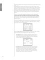
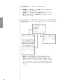
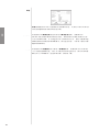
10 DC Trigger Input and Output
Many audio/video components can supply a DC control voltage to
associated equipment in order to induce desired behavior. Your Classé
preampli–er can take advantage of these capabilities in order to be switched
between
operate
and
operate and operate
standby
automatically, usually in concert with the A/V
standby automatically, usually in concert with the A/V standby
preamp itself.
The 1/8th-inch mini mono-jack
Trigger In
provides for remote-controlled
turn-on (that is, toggling between
operate
and
operate and operate
standby
) of the preampli–er.
standby) of the preampli–er.standby
Two 1/8th-inch mini mono-jacks provide individually controllable DC
trigger outputs which can be used for any of a number of purposes, as
described in
The Menu System
. For example, your dealer can program
Trigger Out1
to toggle your Classé power ampli–er between operate and
standby with your CP-700.
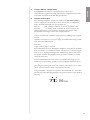
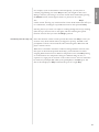
The remote trigger input will respond to the presence of 5-12VDC, with
tip polarity as shown below:
Similarly, the trigger outputs will create a 12VDC signal that can source
up to 100mA of current.
11 Ground terminal
The ground terminal on your preampli–er is most often used for the
ground wire of a turntable, assuming you have the optional phono module
installed (see your authorized Classé dealer for more information on this
option if you are interested). Connecting the ground wire from your
turntable»s tonearm to this screw terminal usually minimizes any hum
or buzzing to which the turntable might otherwise be susceptible. Your
authorized Classé dealer can assist you in handling this problem if it should
arise.
12 DC Power Input
The
DC Power Input
for the CP-700 is located near the middle of the
DC Power Input for the CP-700 is located near the middle of the DC Power Input
rear panel. Connect the provided multi-pin ≈umbilical cord∆ between the
outboard power supply and this connector to provide the preampli–er with
the clean, pure DC power it needs to do its job.
There is also an AC mains switch on the back of the outboard power
supply. Switching the power supply on (assuming the preampli–er is
connected with the umbilical cord) puts the preampli–er in
standby
mode.
standby mode. standby
The preampli–er should also be in
standby
before power is switched off.
standby before power is switched off.standby
Danger! Potentially dangerous voltages and current capabilities
Danger! Potentially dangerous voltages and current capabilities
exist within your power supply, even when disconnected
from AC mains. Do not attempt to open any portion of the
unit’s cabinet. There are no user-serviceable parts inside.
All service of this product must be referred to a qualifi ed
authorized Classé dealer or distributor.

19
ENGLISH
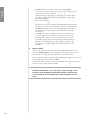
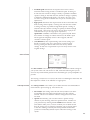
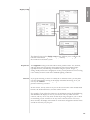
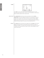
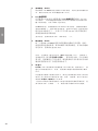
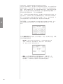
The Remote Control
Your new preampli–er comes with a versatile
remote control
which can control
both the CP-700 itself and several aspects of the rest of a Classé-based system.
The buttons are arranged in logical groups according to their functions.
1 Basic Functions
This section along the top of the remote control groups four functions that
control your basic interactions with the CP-700.
•
Light
switches the backlighting of the remote control on, for
better visibility under low-light conditions. After a few moments
of inactivity, the backlight switches off automatically.
•
Info
takes you directly to the status screen in the LCD menu
system, displaying several items of information about the
CP-700 and its current operational status.
•
Disp
(for
Display
) cycles through the three brightness settings of
Display) cycles through the three brightness settings of Display
the screen display.
•
Standby
toggles the CP-700 between standby and operate.
2 Input Selection & Volume
The
Up
and
Down
arrow keys on the left side of the remote control will
cycle through the active inputs on your CP-700.
If you have inputs you are not using, we suggest deactivating them in order
to provide faster, easier access to the inputs you are actually using. (See the
section
The Menu System
for information on how to do this.)
The Menu System for information on how to do this.)The Menu System
The
Up
and
Down
arrow keys on the right side of the remote control
will raise and lower volume; the square key between them will activate the
Mute
function of the CP-700 (as de–ned in the menu system; see
The
Menu System
for more on your mute options).
Menu System for more on your mute options).Menu System
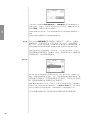
3 Navigation Keys
The central section of the remote control contains the navigation keys.
This array of buttons is similar to what you may have seen on remote
controls for DVD players, and is used for navigation of the menu system
of the CP-700.
•
Home
returns you to the normal input selection controls
normally shown on the LCD screen on the front panel of the
CP-700. This provides a quick way to get back to normal
operation, regardless of how deep you might be in the menu
system.
•
Menu
serves two functions: it calls up the menu system when
you need it in order to adjust something to your preference;
once within the menu system, pressing
Menu
returns you to the
previous level of the menu system. If you press
Menu
when at
the top level of the menu system, it will take you back out of the
menu system to the normal display.

20
ENGLISH
• The
Bal
(balance) key takes you directly to the
balance
screen
in the menu system; once there, you can use the navigation keys
on the remote to select either the
left
or
left or left
right
buttons on the
right buttons on the right
LCD touchscreen, depending on which way you wish to move
the balance. Adjust the relative left-right balance of the system
by using the
Enter
key on the remote to ≈press∆ the appropriate
Enter key on the remote to ≈press∆ the appropriate Enter
button on the display.
•
Up/Down/Left/Right
keys allow you to move within a
Up/Down/Left/Right keys allow you to move within a Up/Down/Left/Right
particular menu screen, changing the highlighted item up/down/
left/right as you like, from the comfort of your listening position.
• The
Enter
key allows you to select the highlighted item, having
Enter key allows you to select the highlighted item, having Enter
the same effect as if you had pressed the button on the LCD
touchscreen.
• The
Tape
key is not a navigation key, per se, but allows you
to easily toggle between listening to the selected source and
listening to the output of your recording device. If you have
a recording device (such as a three-head tape deck) which can
play back a recording while it is being made, you will be able
to compare the original signal to the recording while you are
making it.
4 Fkey Controls
The CP-700 remote control can also control user-de–ned functions as
well. The
F1/F2/F3/F4
keys are available for controlling aspects of the
CP-700 not covered by the other buttons on the remote control.
You are able to choose what the CP-700 should do in response to receiving
the infrared signal that a particular
Fkey
has been pressed. The list of
Fkey has been pressed. The list of Fkey
possible functions is quite extensive, and is found in the menu system (see
the next section in this manual, entitled
The Menu System
).
The Menu System). The Menu System
Note: The Fkeys on all Classé remote controls issue the same
Note: The Fkeys on all Classé remote controls issue the same
infrared commands. This saves you from having to be
sure you have picked up the proper remote, since all your
Classé remotes will perform the same function for each
Fkey.
ページが読み込まれています...
ページが読み込まれています...
ページが読み込まれています...
ページが読み込まれています...
ページが読み込まれています...
ページが読み込まれています...
ページが読み込まれています...
ページが読み込まれています...
ページが読み込まれています...
ページが読み込まれています...
ページが読み込まれています...
ページが読み込まれています...
ページが読み込まれています...
ページが読み込まれています...
ページが読み込まれています...
ページが読み込まれています...
ページが読み込まれています...
ページが読み込まれています...
ページが読み込まれています...
ページが読み込まれています...
ページが読み込まれています...
ページが読み込まれています...
ページが読み込まれています...
ページが読み込まれています...
ページが読み込まれています...
ページが読み込まれています...
ページが読み込まれています...
ページが読み込まれています...
ページが読み込まれています...
ページが読み込まれています...
ページが読み込まれています...
ページが読み込まれています...
ページが読み込まれています...
ページが読み込まれています...
ページが読み込まれています...
ページが読み込まれています...
ページが読み込まれています...
ページが読み込まれています...
ページが読み込まれています...
ページが読み込まれています...
ページが読み込まれています...
ページが読み込まれています...
ページが読み込まれています...
ページが読み込まれています...
ページが読み込まれています...
ページが読み込まれています...
ページが読み込まれています...
ページが読み込まれています...
ページが読み込まれています...
ページが読み込まれています...
ページが読み込まれています...
ページが読み込まれています...
ページが読み込まれています...
ページが読み込まれています...
ページが読み込まれています...
ページが読み込まれています...
ページが読み込まれています...
ページが読み込まれています...
-
 1
1
-
 2
2
-
 3
3
-
 4
4
-
 5
5
-
 6
6
-
 7
7
-
 8
8
-
 9
9
-
 10
10
-
 11
11
-
 12
12
-
 13
13
-
 14
14
-
 15
15
-
 16
16
-
 17
17
-
 18
18
-
 19
19
-
 20
20
-
 21
21
-
 22
22
-
 23
23
-
 24
24
-
 25
25
-
 26
26
-
 27
27
-
 28
28
-
 29
29
-
 30
30
-
 31
31
-
 32
32
-
 33
33
-
 34
34
-
 35
35
-
 36
36
-
 37
37
-
 38
38
-
 39
39
-
 40
40
-
 41
41
-
 42
42
-
 43
43
-
 44
44
-
 45
45
-
 46
46
-
 47
47
-
 48
48
-
 49
49
-
 50
50
-
 51
51
-
 52
52
-
 53
53
-
 54
54
-
 55
55
-
 56
56
-
 57
57
-
 58
58
-
 59
59
-
 60
60
-
 61
61
-
 62
62
-
 63
63
-
 64
64
-
 65
65
-
 66
66
-
 67
67
-
 68
68
-
 69
69
-
 70
70
-
 71
71
-
 72
72
-
 73
73
-
 74
74
-
 75
75
-
 76
76
-
 77
77
-
 78
78


