4
ENGLISH
DEDICATED CIRCUIT AND ELECTRICAL INFO
A “Dedicated Circuit” means that each outlet you plug into should not have
anything else running on that same circuit. The easiest way to verify this is
to locate the main circuit breaker box, and turn o the breaker(s) one at a
time. Once a breaker has been turned o, the only thing that should not have
power to it are the units in question. No lamps, vending machines, fans, sound
systems, or any other item should lose power when you perform this test.
Non-looped (isolated) neutral/grounding means that each circuit must have an individual
neutral/ground connection coming from it, and terminating at an approved earth
ground. You cannot “jumper” a single neutral/ground from one circuit to the next.
ELECTRICAL REQUIREMENTS
For your safety and to ensure good unit performance, the ground on this circuit must
be non-looped (isolated). Please refer to NEC article 210-21 and 210-23. Any alterations
to the standard power cord provided could void all warranties of this product.
Units with LED and Premium LED consoles are designed to be self powered and do
not require an external power supply source to operate. Without an external power
supply, the console’s start-up time may be delayed. Add-on TV’s and other console
accessories require an external power supply. An external power supply will ensure
power is provided to the console at all times and is
required when add-on accessories are used.
For units with an integrated TV (Touch), the TV power
requirements are included in the unit. An RG6 quad
shield coaxial cable with ‘F Type’ compression fittings
on each end will need to be connected to the cardio unit
and the video source. Additional power requirements
are not needed for the add-on digital TV.
110 V UNITS
110 V units require the use of a 100-125 V, 60 Hz and a 15
A “Dedicated Circuit”, with a non-looped (isolated) neutral/
ground for power. This outlet should be a NEMA 5-15R and
have the same configuration as the plug. No adapter should
be used with this product. These cycles can be daisy-chained
together with up to 4 units per 15 A dedicated circuit.
Matrix daisy-chain cord adapters are sold separately.
220 V UNITS
220 V units require the use of a 216-250 V, 50 Hz and a 15
A “Dedicated Circuit”, with a non-looped (isolated) neutral/
ground for power. This outlet should be a NEMA 6-15R and
have the same configuration as the plug. No adapter should
be used with this product. These cycles can be daisy-chained
together with up to 4 units per dedicated 15 A circuit.
Matrix daisy-chain cord adapters are sold separately.
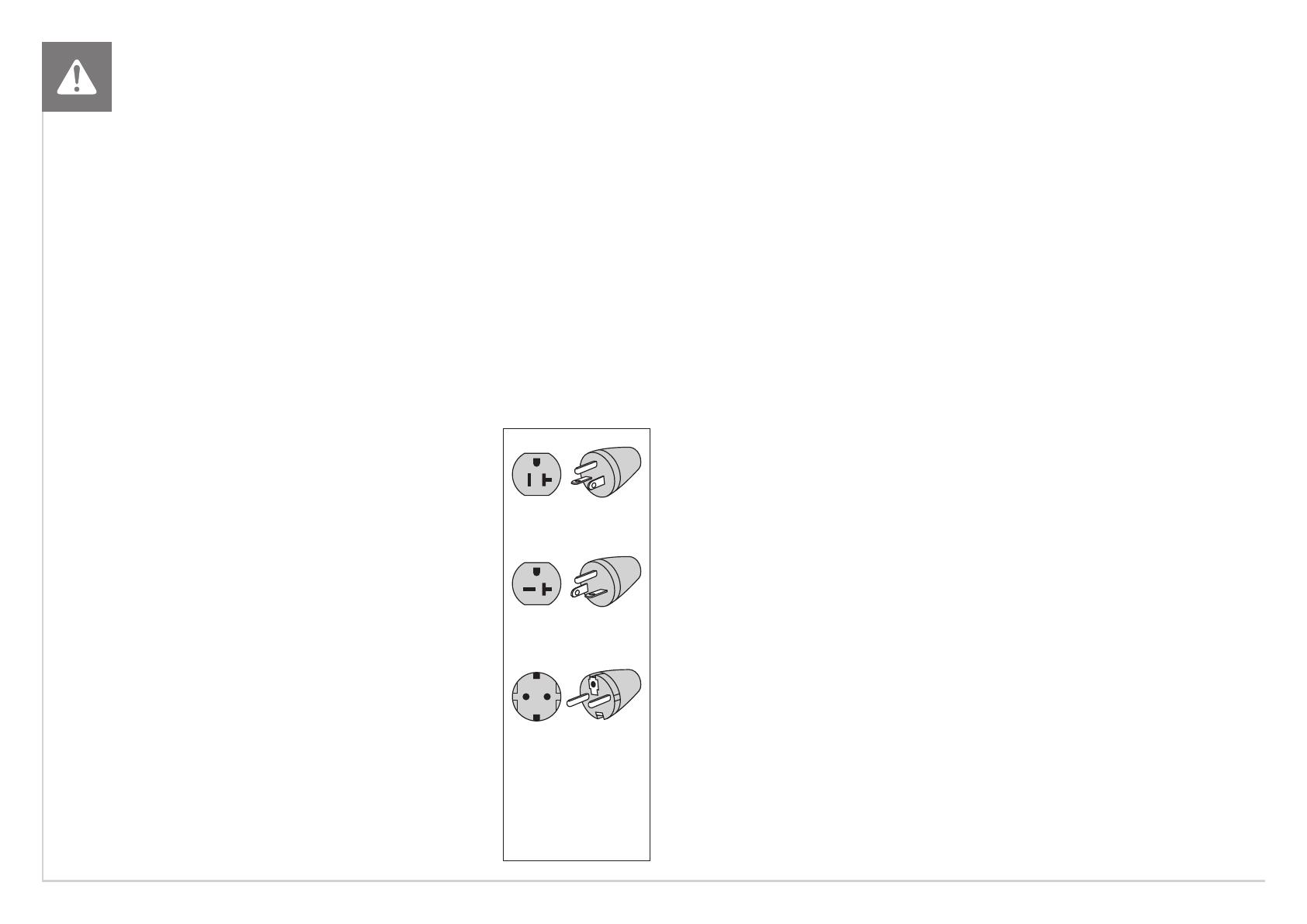
POWER REQUIREMENTS
North American and
European power
cord plugs shown.
Depending on your
country, the plug
type may vary.
110 NEMA 5-20P
PLUG (N.A.)
220 NEMA 6-20P
PLUG (N.A.)
EURO PLUG
(EUROPE)
GROUNDING INSTRUCTIONS
The unit must be grounded. If it should malfunction or breakdown, grounding provides
a path of least resistance for electric current to reduce the risk of electric shock. The unit
is equipped with a cord having an equipment-grounding conductor and a grounding
plug. The plug must be plugged into an appropriate outlet that is properly installed and
grounded in accordance with all local codes and ordinances. If the user does not follow
these grounding instructions, the user could void the Matrix limited warranty.
ADDITIONAL ELECTRICAL INFO
In addition to the dedicated circuit requirement, the proper gauge wire must be used
from the circuit breaker box, to each outlet that will have the maximum number of units
running o of it. If the distance from the circuit breaker box to each outlet, is 100 ft (30.5
m) or less, then 12 gauge wire should be used. For distances greater than 100 ft (30.5
m) from the circuit breaker box to the outlet, a 10 gauge wire should be used.
ENERGY SAVING / LOW-POWER MODE
All units are configured with the ability to enter into an energy saving / low-power mode when
the unit has not been in use for a specified period of time. Additional time may be required to
fully reactivate this unit once it has entered the low-power mode. This energy saving feature
may be enabled or disabled from within the ‘Manager Mode’ or ‘Engineering Mode.’
ADD-ON DIGITAL TV
Add-on digital TV’s require additional power and must use an external power
supply. An RG6 coaxial cable with ‘F Type’ compression fittings will need to be
connected between the video source and each add-on digital TV unit.
FCC REGULATIONS (USA ONLY)
This equipment has been tested and found to comply with the limits for a Class B digital device, pursuant
to part 15 of the FCC rules. These limits are designed to provide reasonable protection against harmful
interference in a residential installation. This equipment generates, uses and can radiate radio frequency
energy and, if not installed and used in accordance with the instructions, may cause harmful interference
to radio communications. However, there is no guarantee that interference will not occur in a particular
installation. If this equipment does cause harmful interference to radio or television reception, which can be
determined by turning the equipment o and on, the user is encouraged to try to correct the interference by
one or more of the following measures:
• Reorient or relocate the receiving antenna.
• Increase the separation between the equipment and receiver.
• Connect the equipment into an outlet on a circuit dierent from that to which the receiver is connected.
• Consult the dealer or an experienced radio/TV technician for help.
FCC RF Radiation Exposure Statement:
1. This Transmitter must not be co-located or operating in conjunction with any other antenna or
transmitter.
2. This equipment complies with FCC RF radiation exposure limits set forth for an uncontrolled
environment. This equipment should be installed and operated with a minimum distance of 20
centimeters between the radiator and your body.


