
F Two
Operating Manual
操作手册

F Two Active Subwoofer
General description
The Genelec F Two is a very compact
active subwoofer designed to comple
-
ment up to ve Genelec G One or G Two
active loudspeakers as a .1 / LFE channel
subwoofer in a 5.1 system or a pair of the
slightly bigger G Threes. Linked together
two F Two’s can also be used with G Fours.
The F Two extends the system’s bass
response down to 27 Hz and integrates
perfectly with the main loudspeakers in
any environment. The playback level for the
whole system is conveniently controlled by
the wireless volume control provided with
the subwoofer. A wired volume control is
available as an option.
The F Two has integrated bass manage-
ment for the two output channels which
directs frequencies below 85 Hz to the
subwoofer and higher frequencies through
the output connectors to the main loud
-
speakers. When using the subwoofer
for the .1/LFE channel of a multichannel
system, we recommend that bass manage
-
ment is done in the processor or receiver
and only the LFE channel is connected to
the subwoofer.
Installation
Before connecting the audio signals, ensure
that all equipment is switched off.
As the F Two contains its own amplier, no
separate power amplier is needed. Never
connect the F Two to the loudspeaker out-
puts of a power amplier, integrated ampli-
er or receiver.
Please follow the steps listed below for a
succesful setting up of the subwoofer:
1. Check the contents of the shipment.
in addition to the subwoofer, there is a
wireless remote control, a mains cable,
an IR extension cable and a Quick Setup
Guide.
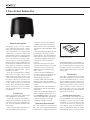
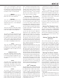
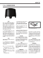
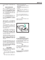
2. Pull out the battery insulating strip from
the underside of the remote control as
shown in gure 1. This strip insulates the
battery from the contacts on the remote
control during shipping and the remote
control does not function before it is
removed.
3. Place the subwoofer in its position.
4. Connect audio cables from your signal
source(s). You can connect up to two
digital audio sources and two analog
audio sources.
5. Connect the main loudspeakers to
the output connectors of the subwoofer.
You can use either balanced XLR or
unbalanced RCA connectors.
6. Set the “LEVEL +10” and “-10 dB”
switches on the subwoofer and main
loudspeakers according to Table 2 on this
manual.
7. Adjust the phase of the subwoofer as
instructed in this manual and the Quick
Setup Guide.
8. Use test recordings and familiar music
pieces to judge the sound balance. Use
the “SUBWOOFER LEVEL” rotary control
and the “BASS ROLL-OFF” dip switches
to ne-tune the balance. If this fails,
consider relocating the subwoofer.
Operating Environment
The F Two subwoofer is designed for
indoor use only. The ambient temperature
should be 15-35 °C (50-95 °F) and the rela
-
tive humidity 20-80 %. Condensation is not
allowed. If it has been stored or transported
in a cool environment, the product must be
allowed to warm up in its packing to the
ambient temperature before connecting
mains power.
Connectors
The F Two is equipped with both analog
and digital signal input connectors, that
can be used simultaneously to connect
up to four audio sources (two analog, two
digital). Switching between sources is done
with the Select button on the connector
panel or with the “<” and “>” buttons on
the remote control. The colour of the LED
light on the subwoofer enclosure indicates
which source is selected.
Analog Input Connectors
The F Two has two stereo inputs (3.5 mm
jack and L/R RCA connectors) and an LFE/
LINK RCA connector. The stereo inputs
are parallel, so you can connect two audio
sources at the same time, just play only
one of them at a time. The Select function
does not work between these two inputs.
The LFE/LINK input is used for the LFE
Figure 1. Removing the battery insulating strip
from the remote control

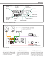
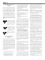
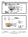
Figure 2. Connectors and controls of the F Two.
(.1) signal in a 2.1 or 5.1 channel sound
system or as the signal input in a multiple
subwoofer system (see chapter Using Mul
-
tiple Subwoofers). The LFE/LINK input has
a 120 Hz low pass lter, so it is not suitable
for full frequency range signals.
Digital Input Connectors
The F Two has two digital signal input con-
nectors, one coaxial and one optical, that
accept stereo PCM format digital signal.
You can connect two digital sources and
switch between them using the Select
function.
Analog Output Connectors
The F Two has two pairs of analog stereo
L/R output connectors, one with RCA con
-
nectors and the other with balanced XLR
male connectors. Connect signal cables
from these connectors to the main speak
-
ers. Both connector pairs carry the same
SYSTEM
VOLUME
CONTROL
RIGHT
LEFT
LFE/LINK
PHASE
270°
OUT
LR
L
R
LINK
SELECT
OPTICALCOAXIAL
IN
90°
180°
LINK
+10dB
10 dB
LEVEL
IR IN
MAINS INPUT
50 /60Hz150 W
100240 V~
STEREO
MAX MIN
DIGITAL AUDIO IN
SUBW LEVEL
6 dB
4dB
2dB
ROLL OFF
HT MODE
ISS SENSITIVITY LOW
ISS
LED OFF
ON
OFF
ON
OFF
DIP SWITCH GROUP 1:
HT MODE
ISS SENSITIVITY LOW
ISS
LED OFF
AUDIO OUTPUT CONNECTORS:
XLR L AND R
RCA L AND R
RCA LINK
DIGITAL AUDIO INPUTS:
RCA COAXIAL
TOSLINK OPTICAL
MAINS INPUT
POWER BUTTON
IR IN CONNECTOR
SELECT BUTTON
SYSTEM VOLUME
CONTROL CONNECTOR
SUBWOOFER LEVEL
ROTARY ADJUSTMENT
DIP SWITCH GROUP 2:
ROLL OFF
PHASE
LINK
LEVEL
ANALOG AUDIO INPUTS:
RCA L AND R
3.5 MM STEREO JACK
LFE/LINK
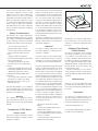
Figure 3. Audio cabling
SYSTEM
VOLUME
CONTROL
RIGHT
LEFT
LFE/LINK
PHASE
270°
OUT
LR
L
R
LINK
SELECT
OPTICALCOAXIAL
IN
90°
180°
LINK
+10 dB
10 dB
LEVEL
IR IN
MAINS INPUT
50/60Hz 150 W
100 240 V~
STEREO
MAX MIN
DIGITAL AUDIOIN
SUBW LEVEL
6 dB
4dB
2dB
ROLL OFF
HT MODE
IS
S S
ENSITIVITY LO
W
ISS
LED OFF
ON
OFF
ON
OFF
DIGITAL SIGNAL SOURCES:
TV, STREAMER, SOUND CARD ETC.
ANALOG SIGNAL SOURCES:
PHONE, COMPUTER, AV REVEIVER ETC.
Tuner 87.5 MHz
GIZMO
POSSIBLE ADDITIONAL SUBWOOFER.
USE THE LFE/LINK INPUT AND SET THE
”LINK” DIP SWITCH TO ”ON”.

signal so you can use main speakers with
either RCA or XLR input connectors. These
outputs are high pass ltered at 85 Hz (See
chapter Bass Management). Additionally,
the LINK RCA output provides a summed
signal of both channels. Use this connector
as a signal output to the next subwoofer
when you want to connect several sub
-
woofers together. See chapter “Using Mul-
tiple Subwoofers” for more information.
System Volume Control Connector
This connector allows connecting the
Genelec 9310A Wired Volume Control
which is available as an accessory. When
connected, the 9310A controls the volume
of the whole system, including the main
speakers.
IR IN Connector
If the F Two is used with an infrared type
remote control (see chapter Use with IR
Remote Controls) and the desired location
of the subwoofer does not allow an unob
-
structed line of sight to the receiver located
next to the LED in one of subwoofer’s feet,
the IR extension cable provided with the
subwoofer can be connected here. The
receiver end of the cable is then brought
to a location where the IR remote control
reception works conveniently, for instance
close to the IR receiver of a television set
when using the subwoofer and speakers
with a TV.
Subwoofer
placement
Bass Roll-Off
Near a wall -2 dB
In a corner -4 dB
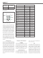
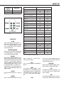
Table 1. Suggested Bass Roll-Off settings in
typical situations
Figure 4. F Two remote control
Main loudspeaker model F Two Level Dip switch setting
-10 dB switch +10 dB switch
G One A OFF OFF
G One B OFF OFF
G One B -10 dB Dip ON ON OFF
G Two A OFF OFF
G Two B OFF OFF
G Two B -10 dB Dip ON ON OFF
G Three A OFF OFF
G Three A +10 Dip ON OFF ON
G Three B OFF OFF
G Three B -10 Dip ON ON OFF
G Four A OFF OFF
G Four A +10 dB Dip ON OFF ON
8010A OFF ON
8010A -10 dB Dip ON OFF OFF
8020A OFF ON
8020B OFF ON
8020C OFF ON
8020D OFF ON
8030A OFF ON
8030B OFF ON
8030C OFF ON
8040A OFF ON
8040B OFF ON
M030 OFF ON
Table 2. Suggested Level switch settings with different main loudspeakers
Functions And Controls
HT Mode
Turn this switch to “ON” when you connect a
sound source with its own volume control to
the analog inputs of the F Two. In this mode
the volume control of the F Two does not
have effect on the analog signals. However,
it works with the digital inputs, so you can
use them to connect other signal sources.
ISS Sensitivity Low
If the Intelligent Signal Sensing (ISS) func-
tion switches the subwoofer on when there
is no audio signal present, turning this
switch to “ON” reduces the triggering sen
-
sitivity of the function.
ISS
The Intelligent Signal Sensing (ISS) func-
tion monitors the audio signal fed to the
subwoofer. If there is no signal for approxi
-
mately 45 minutes, the function switches
the subwoofer to Standby mode, reduc
-
ing the power consumption to less than
0.5 Watts. When the signal resumes, the
subwoofer powers up again. There is a
slight delay in the automatic powering up.
In those environments where the subwoofer
is required to be on all of the time, the ISS
VOLUME
UP
VOLUME
DOWN
SELECT
BUTT
ONS
MUTE
POWER

function can be disabled by setting the
“ISS” switch to the “OFF” position. Then
the subwoofer is continuously powered and
can be turned off using the power button on
the remote control or connector panel.
LED Off
This switch deactivates the status indicator
LED on the “foot” of the subwoofer.
Roll-Off
These two switches attenuate the sub-
woofer’s bass response. At 27 Hz the
attenuation levels are -2, -4 and -6 dB (both
switches “ON”).
Phase
These two switches provide phase adjust-
ment for the subwoofer in -90 degree incre-
ments. See chapter “Phase Alignment”.
Link
This switch selects the analog inputs and
disables input channel selection. In addi
-
tion, it disables the remote control and sets
the subwoofer’s level to maximum. Set this
switch to “ON”, when using the subwoofer
as a “slave” in a multiple subwoofer system.
See chapter “Using Multiple Subwoofers”.
Level
These two switches allow adjusting the
subwoofer’s level by -10 dB or +10 dB,
providing level matching with different
main speaker models. See Table 2 for some
examples.
Subwoofer Level
This rotary adjustment adjusts the play-
back level of the subwoofer. The level is
increased by turning the adjustment clock
-
wise and reduced by turning it counter-
clockwise.
Select
This button allows signal input selection
between the two digital inputs and the
analog input and initiation of the match
-
ing procedure for IR remote controls (see
Matching IR Remote Controls).
Power
This button switches the subwoofer
between Standby and Power mode. Note
that this button does not completely dis
-
connect the subwoofer from the mains
power. If this is necessary, the subwoofer’s
mains cable must be disconnected. This
button can also be used for restoring the
factory settings by keeping it depressed for
10 - 15 seconds. This returns the volume
setting on the remote control to factory
level and deletes possible remote control
pairing and IR remote control matching.
Also the source selection returns to auto
-
matic, which is the factory setting.
Positioning In The Room
The placement of the subwoofer in the
room affects the overall frequency response
and sound level of the system dramatically,
as at low frequencies the effects of the
room are strong. Even a slight change in
the location of the subwoofer can cause a
marked difference in the frequency balance
and often patient and methodical experi
-
mentation and testing is needed to nd the
optimum placement.
The placement will also affect the bass
roll-off rate and the phase difference
between the main loudspeakers and the
subwoofer. These effects can be compen-
sated using the controls in the subwoofer
but we recommend that at rst you leave
the switches untouched and concentrate
on nding the position where the subwoofer
gives the smoothest response, and only then
use the controls to ne-tune the balance and
phase alignment between the subwoofer
and the main loudspeakers.
Start by placing the subwoofer close to the
center of the front wall. We recommend
a distance of less than 60 cm / 24” to the
wall. This position gives increased acous-
tic loading and sound pressure level due to
the proximity of the front wall and oor. Ide-
ally the subwoofer and main loudspeakers
should be positioned symmetrically and at
an equal distance from the listening position.
If the frequency balance is not quite right,
try moving the subwoofer to the left or right
along the wall so that different room modes
are excited at different levels. Positioning
the subwoofer close to a corner will boost
the bass level at lower frequencies and may
cause asymmetrical spatial imaging.
ISS
TM
Autostart
The automatic power saving function ISS
(Intelligent Signal Sensing) can be activated
by setting the “ISS” switch on the connec
-
tor panel to “ON.” Automatic powering
down to standby mode happens after a
certain time when playback has ended. The
power consumption in standby mode is
typically less than 0.5 watts. Playback will
automatically resume once an input signal
is detected from any source.
Alternatively, the subwoofer can be acti-
vated by pushing any button on the remote
control.
There is a slight delay in the automatic
powering up. If this is undesirable, the ISS
TM
function can be disabled by setting the “ISS”
switch on the connector panel to “OFF.” In
this mode, the subwoofer is powered on and
off using the remote control or the power
button on the connector panel.
The “ISS SENSITIVITY LOW” switch
lowers the triggering sensitivity of the
ISS function. This can be necessary if the
subwoofer “wakes up” even if there is no
audio signal.
Setting The Playback Level
The “LEVEL +10 dB and LEVEL -10 dB”
switches and the rotary “SUBWOOFER
LEVEL” level adjustment can be used for
matching the subwoofer’s playback level
with the main loudspeakers (See Table 2).
Fine tuning can be done with the rotary
adjustment knob.
Setting The Bass Roll-Off
Switches
The acoustic response of the subwoofer
may have to be matched to the charac
-
teristics of the room and the positioning in
which it will be used (see Table 1). To adjust
the subwoofer to match these character
-
istics use the ‘’BASS ROLL-OFF’ control
switches located on the connector panel.
When all Roll-Off switches are ‘OFF’, a at
anechoic response is obtained.
Setting The Phase Control
The effect of incorrect phase alignment
between the main loudspeakers and
the subwoofer is a drop in the frequency
response of the whole system at the main
loudspeaker / subwoofer crossover fre
-
quency. The phase difference between the
main loudspeakers and subwoofer at the
listening position is dependent upon the
distance from the listener to the subwoofer
in relation to the main loudspeakers. To
avoid phase differences between the
left and right main loudspeakers and
the subwoofer, the subwoofer should be
placed close to the center of the front loud
-
speaker array.
Two phase matching switches allow com-
pensation for incorrect phase alignment.
Four settings are provided between 0° and
-270°.

Coarse Phase Correction
Method
Connect an audio frequency signal gen-
erator to a signal input on the subwoofer
which has a main loudspeaker connected
to the corresponding “OUT” connector.
If the loudspeakers are placed at differ
-
ent distances from the listening position,
choose the loudspeaker that is nearer.
Set the generator to 85 Hz. If a signal gen-
erator is not available, it is possible to use
an audio test recording which has a test
frequency in the range 70 Hz to 100 Hz.
Suitable test signals can be downloaded at
www.genelec.com and found in some smart
phones.
Toggle the -180° phase
switch ‘ON’ and ‘OFF’ and
set it to the position which
gives the lowest sound
level at the listening posi
-
tion.
Next toggle the -90°phase
switch ‘ON’ and ‘OFF’,
and again set it to the
position which gives the
lowest sound level.
Finally, set the -180°phase
switch to the opposite set
-
ting.
Matching IR Remote
Controls
The F Two subwoofer can be used with
most IR remote controls, providing con
-
venient use with, for instance, the remote
control of a TV set when connected to it
via a xed level digital signal input. Turn the
subwoofer upside down so you can easily
reach the “Select” button on the subwoof
-
er’s connector and the status indicator LED
on the subwoofer’s foot is visible. The IR
receiver is located in the LED. Note that the
“Select” buttons on the RF remote control
provided with the subwoofer do not actu
-
ate the matching.
The matching procedure is as follows:
• Keep the “Select” button on the
subwoofer depressed until the status
indicator LED starts blinking red.
• Choose the button on the remote
control that you want to actuate “volume
up” function. Keep it depressed until the
LED stops blinking. With some remote
controls pressing the button multiple
times works better.
• Now the LED blinks green, indicating
that the button for “volume down” can be
selected. Follow the procedure described
above.
• Next the LED blinks blue for selection of
the button for “Select” button.
• Yellow LED indicates the selection of
“Mute” button.
• Magenta LED indicates the selection of
“Power” button.
A short press on the “Select” button allows
you to skip a step in the procedure, if you
do not want to “teach” all the commands
listed above. If you want to interrupt the
procedure, press “Select” for approxi
-
mately two seconds. This saves the set-
tings made so far. If you don’t want to
save the settings, press the Power button
for two seconds. This will also delete the
matching settings done by that point. If you
want to change the matched buttons, just
redo the matching process.
Matching The RF Remote
Control To The Subwoofer
The remote controls delivered with F Two
subwoofers will function with any other F Two
subwoofer as well. If this is not desirable, for
instance when there are several F Two sub
-
woofers in the same premises, and the user
wishes to avoid the situation that more than
one subwoofer reacts to the commands
given by each remote control, the remote
controls can be matched to operate only one
subwoofer.
1. Press and hold down the “Power” and
“Select “ buttons on the subwoofer until the
LED starts blinking white.
2. While the LED is blinking, rst press
and hold down the volume “+“ button on
the remote control and then the volume “-“
button. Keep both buttons pressed for a few
seconds until the status indicator LED on the
subwoofer stops blinking. This indicates that
matching is completed and the matching
operation ends automatically.
Now the subwoofer should only respond
to commands given by the matched remote
control, and respectively, the matched
remote control should not work with other
F Two units. For cancelling the matching
operation while the LED is blinking, press
and hold down the ”Power” button on the
subwoofer for two seconds. If you wish to
undo a matching completely, press and hold
down the ”Power” button on the subwoofer
for ten seconds.
NOTE: In some cases the local WiFi
network can cause problems with the RF
remote control, if they operate on the same
wavelength. We recommend the use of an IR
remote control in these cases.
Using Multiple Subwoofers
The Genelec F Two subwoofer is equipped
with an LFE/LINK output connector to pro
-
vide an easy way of coupling two or more
subwoofers together in high SPL applica
-
tions, for instance when using the subwoof-
ers with Genelec G Four active loudspeak-
ers. Connected as described below, the
“master” subwoofer controls the volume
of all subwoofers linked to it through this
connector.
Connect an RCA cable from the LINK con-
nector of the “master” subwoofer to which
the main loudspeakers are connected, to the
LFE / LINK connector of the other, “slave”
subwoofer and turn the LINK dip switch on
the “slave” subwoofer to “ON”.
In the LINK mode, the subwoofer volume
is automatically set to maximum and the
“slave” subwoofer only reacts to the power
on/off commands given with a remote
control. It follows the volume adjustment
and source channel selection done in the
“master” subwoofer.
When two subwoofers connected in this
way are positioned close to one another,
bass level increases by 6 dB. Three sub-
woofers give an SPL increase of 9.5 dB and
four subwoofers 12 dB compared to a single
subwoofer.
The rotary “SUBWOOFER LEVEL” adjust-
ment knob should be set in the same posi-
tion as that of the “master” subwoofer unless
the subwoofers are placed in very different
positions acoustically, for example one in
a corner and one far from corners. In such
case, it is advisable to measure the loudness
of each subwoofer separately and adjust
them individually for correct balance.
Phase and Bass Roll-Off adjustments should
be done individually for each subwoofer in the
chain, especially if they are not placed close
together. To check the phase alignment for
the “master” subwoofer switch off the “slave”
subwoofer and follow the instructions given in
the previous sections.
To adjust the phase alignment of the
PHASE
270°
90°
180°
ON
OFF
PHASE
270°
90°
180°
ON
OFF
PHASE
270°
90°
180°
ON
OFF

“slave” subwoofer, you need to switch off
the “master” subwoofer, connect a signal
cable from one of the “slave” subwoofer’s
output connectors to the corresponding
loudspeaker and switch the LINK switch to
“OFF”. This effectively changes the “slave”
to “master” mode and the phase adjustment
can be carried out. Return the connections
and LINK setting on the “slave” subwoofer
back to the “ON” setting after completing
the adjustment.
Safety Considerations
The Genelec F Two complies with interna-
tional safety standards. However, to ensure
safe operation and maintain the equipment
in safe operating condition the following
warnings and cautions must be observed.
• Do not use this product with an
unearthed mains cable or a mains
connection without the protective earth
contact as this may lead to personal
injury.
• Danger of explosion if battery is
incorrectly replaced. Replace only with the
same or equivalent type.
• The battery shall not be exposed to
excessive heat such as sunshine, re or
the like.
• Servicing and adjustment must only be
performed by qualied service personnel.
• Opening the subwoofer is strictly
prohibited except by qualied service
personnel.
• Do not expose the subwoofer to water
or moisture. Do not place any objects
lled with liquid, such as vases on the
subwoofer or near it.
Note that the amplier is not completely
disconnected from the AC mains service
unless the mains cable is removed from the
amplier or the mains outlet.
Warning!
This equipment is capable of deliver-
ing sound pressure levels in excess of 85
dB, which may cause permanent hearing
damage.
Compliance To FCC Rules
Remote control
This device complies with Part 15 of the
FCC Rules. Operation is subject to the fol
-
lowing two conditions:
(1) this device may not cause harmful inter
-
ference, and (2) this device must accept
any interference received, including inter
-
ference that may cause undesired opera-
tion. This product emits radio frequency
energy, but the radiated output power of
this device is below FCC radio frequency
exposure limits. This equipment complies
with FCC RF radiation exposure limits forth
for an uncontrolled environment. Neverthe
-
less, the device should be used in such a
manner that the potential for human con
-
tact with the antenna during normal opera-
tion is minimized.
Changes or modifications not expressly
approved by the party responsible for com
-
pliance could void the user’s authority to
operate the equipment.
Subwoofer
This device complies with part 15 of the
FCC Rules. Operation is subject to the fol
-
lowing two conditions:
This device may not cause harmful inter-
ference, and this device must accept any
interference received, including interfer
-
ence that may cause undesired operation.
Note: This equipment has been tested and
found to comply with the limits for a Class
B digital device, pursuant to part 15 of
the FCC Rules. These limits are designed
to provide reasonable protection against
harmful interference in a residential instal
-
lation. This equipment generates, uses and
can radiate radio frequency energy and, if
not installed and used in accordance with
the instructions, may cause harmful inter
-
ference to radio communications. However,
there is no guarantee that interference will
not occur in a particular installation. If this
equipment does cause harmful interference
to radio or television reception, which can
be determined by turning the equipment
off and on, the user is encouraged to try to
correct the interference by one or more of
the following measures:
• Reorient or relocate the receiving
antenna.
• Increase the separation between the
equipment and receiver.
• Connect the equipment into an outlet
on a circuit different from that to which the
receiver is connected.
• Consult the dealer or an experienced
radio/TV technician for help.
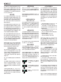
Figure 5. Changing the remote control battery
Modications not expressly approved by
the manufacturer could void the user’s
authority to operate the equipment under
FCC rules.
Changing The Remote
Control Battery
The remote control battery can be changed
by turning the battery cover on the back
of the remote control anticlockwise. Use
a small screwdriver under the right side of
the battery (see gure 5) to wedge the bat-
tery out. Replace the battery with a similar
CR2032 type battery. Insert the battery with
the left side rst as shown in gure 4 and
close the battery cover.
Take the used battery to your local bat-
tery recycling point. Under no circumstances
should the battery be disposed with general
dry waste.
Maintenance
There are no user serviceable parts inside
the subwoofer. Any maintenance of the unit
must only be performed by qualied service
personnel.
Guarantee
This product is supplied with two year
guarantee against manufacturing faults or
defects that might alter the performance of
the unit. By registering your product at:
www.community.genelec.com
You can get an additional three year guaran-
tee that covers the spare parts.

Operating Manual
F Two
AMPLIFIER SECTION
CONNECTORS
SYSTEM SPECIFICATIONS
F Two
Free eld frequency response (-6 dB) Main 27 Hz...85 Hz
LFE 27 Hz...120 Hz
Maximum short term sine wave SPL output
averaged from 30 to 85 Hz, measured in half
space at 1 meter
103 dB
Self generated noise level in half space at 1 m
on axis (A-weighted)
≤ 5 dB SPL
Driver, magnetically shielded 205 mm (8")
Weight 8.5 kg (18.7 lb)
Dimensions
Height
Diameter
300 mm (11
13
/
16
”)
362 mm (14
1
/
4
”)
F Two
Amplier short term output power
(Long term output power is limited by driver
unit protection circuitry)
150 W
Amplier system THD at nominal output
≤ 0.05 %
Mains voltage 100 - 240VAC 50/60 Hz
Power consumption (average)
Stand by
Idle
Full output
0.5 W
11 W
150 W
F Two
Analog audio inputs 10 kOhm
RCA
3.5 mm stereo jack
L, R, LFE
1
Digital audio inputs
Optical Toslink
Coaxial RCA 75 Ohm
1
1
Audio outputs
XLR balanced
RCA
L, R
L, R, LINK
CROSSOVER SECTION
F Two
Subsonic lter (18 dB/octave) below 27 Hz
Crossover frequency
(subwoofer/main channels)
85 Hz
LFE channel cutoff frequency 120 Hz
Midband rejection >400 Hz
>50 dB
Analog input level for 90 dB SPL output at
1 m
-10 dBu at level control
max
Digital input level for 90 dB SPL output at 1 m -21 dBFS at level control
max
Digital input word length 16...24 bits
Digital input sample rate 32...96 kHz
Sensitivity adjustment range 18 dB
Level dip switches +10 dB and -10 dB
Bass Roll-Off control operating range
in 2 dB steps
From 0 to -6 dB @ 27 Hz
Phase matching control in 90° steps From 0 to -270° @ 85 Hz

F Two 有源超低音音箱
图1. 将无线遥控器的电池绝缘片取出
概述
真力 F Two 是一款紧凑型有源超低音音箱,可
以作为多声道音响系统中的LFE声道搭配5只
真力G One或者G Two主动式有源音箱使用,
或者搭配一对更大的G Three使用。两只F Two
串接也可以搭配G Four系统使用。F Two 可与
主音箱完美衔接,将整个系统的低频下潜扩展
至 27 Hz。整个系统的音量控制非常方便,可以
通过随机附送无线遥控器进行调节。也可以选
择有线音量旋钮(选购)进行控制。
F Two具有完善的低频管理功能,能对2个输出
声道进行低频管理,音箱将频率在 85 Hz 以下
的内容分配由F Two进行播放;高于85 Hz 的
声音信号经输出接口送给全频音箱(G系 列 )进
行播放。当将F Two做为多通道音响系统中的
LFE声道使用时,我们建议用影院处理器或者
AV前级进行低频管理,而该超低音音箱仅连接
LFE声道。
安装
在连接音频信号前,请确保所有设备的电源开
关都处于关闭状态。
F Two 配有专属的独立功放,不需要单独配置
外部功放。注意!切勿将 F Two 连在后级功放
或合并式功放的音响输出接口上(通常为一黑
一红的端子接头)。
请根据下列步骤,即可成功设置超低音音箱:
1. 检查音箱配套的附件,包含一个无线遥控
器,一根电源线,一根红外延长线和一本快速
安装指南。
2. 检查音箱配套的附件,包含一个无线遥控
器,一根电源线,一根红外延长线和一本快速
安装指南。
3. 正确摆放超低音音箱。
4. 从音源连接音频信号线到音箱。您最多可
以连接两个数字音源和两个模拟音源。
5. 从超低音音箱的输出接口连接全频音箱。
您可以使用平衡卡侬接口或者非平衡莲花接
口。
6. 根据表2,在超低音音箱和主音箱上设置“
音量+10”和“ -10dB”开 关 。
7. 按照本手册和《快速安装指南》中的说明调
节超低音音箱的相位。
8. 使用测试音频素材和熟悉的音乐片段来
判断声音的平衡。可使用“SUBWOOFER
LEVEL(超低音音量)”控制旋钮和“BASS
ROLL-OFF(低频滚降)”拨档开关微调声音
的平衡。如果效果不理想,请尝试挪动超低
音音箱的位置。
使用环境
F Two超低音音箱仅限室内使用。允许的环境
温度为15-35摄氏度(50-95华氏度),相对湿度
为20%-80%。使用环境中禁止出现冷凝。如果
此产品从温度较低的储存或运输环境转移至
温暖的环境中时,必须先放置在包装中,让箱
体温度恢复到室温后方可连接电源。
连接
F Two 包含模拟输入接口和数字输入接口,最
多可同时连接四个音源(两个模拟音源,两个
数字音源)。可以通过接口板上的“选择”按键
或者无线遥控器上的 “<” 和 “>” 按键切换不
同的音源。超低音音箱上的LED灯会提示目前
选择的音源。
模拟输入接口
F Two具有两组立体声输入接口(3.5毫米耳
机插口和左右声道的莲花接口)和一个LFE声
道/串接的莲花(RCA)输入接口。两组立体
声输入并行,所以可以同时连接两个音源,但
请不要同时播放。“选择”按键无法切换这两组
立体声输入源。LFE声道输入用于连接2.1或者
5.1声道音频系统中LFE声道的信号,或者用作
多只超低音系统的信号输入(请参阅使用多只
超低音音箱的章节)。LFE声道输入需要经过
120Hz的低通滤波器,因此不适用于连接全频
带的信号。
数字输入接口
F Two具有两个数字信号输入接口,一个同轴
接口和一个光纤接口,可接收PCM格式的立体
声数字信号。您可以接入两个数字音源,并通
过“选择”按键进行切换。
模拟输出接口
F Two具有两对模拟立体声输出接口。其中一
对是莲花(RCA)接口,另外一对是平衡卡侬母
(XLR)接口。使用信号线将这些接口连接到
全频音箱。这两对接口传输的信号相同,您可
以使用任意一对接口连接全频音箱。接口输
出的信号经过85Hz的高通滤波器(请参阅低
音管理章节)。此外,串接输出莲花接口(LINK
RCA)输出的是两个声道的混合信号。当需要
在一个系统中连接多只超低音音箱时,该接口
可以将信号串接给下一只超低音音箱。更多信
息请参阅“使用多只超低音音箱”。

图2. F Two的接口和控制键
图3. 音频连接
系统音量控制器接口
该接口用于连接Genelec 9310A有线音量控制
器(选购)。9310A可以控制整个系统的音量,包
括全频音箱。.
红外输入接口
如果F Two和红外遥控器一起使用(请参阅配
合红外遥控器使用部分),而音箱所在的位置
受限,使得位于音箱脚上的红外接收器与操作
者之间有阻挡,可以用音箱附带的红外延长线
连接至该接口。将线缆末端的接收器放置于接
收红外控制信号便利的地方。例如,当音箱和
电视连接使用时,将该接收器靠近电视的红外
接收器。

超低音音箱
摆放位置
低频滚降开关
靠墙放置 -2 dB
放置于角落 -4 dB
表1. 在典型情况下建议的低频滚降开关设置
图4. F Two 遥控器
主音箱型号 F Two音量拨挡开关设置
-10 dB 开关 +10 dB 开关
G One A OFF OFF
G One B OFF OFF
G One B -10 dB Dip ON ON OFF
G Two A OFF OFF
G Two B OFF OFF
G Two B -10 dB Dip ON ON OFF
G Three A OFF OFF
G Three A +10 Dip ON OFF ON
G Three B OFF OFF
G Three B -10 Dip ON ON OFF
G Four A OFF OFF
G Four A +10 dB Dip ON OFF ON
8010A OFF ON
8010A -10 dB Dip ON OFF OFF
8020A OFF ON
8020B OFF ON
8020C OFF ON
8020D OFF ON
8030A OFF ON
8030B OFF ON
8030C OFF ON
8040A OFF ON
8040B OFF ON
M030 OFF ON
表2. 针对不同主音箱,建议的音量开关设置
功能和控制
HT模式
当您将带有音量控制功能的音源连接到F Two
的模拟输入时,请将此开关拨到“ON”。在此模
式下,F Two的音量控制对模拟输入信号无效,
不过它仍然对数字输入起作用,所以您依然可
以控制数字音源的音量。
降低智能休眠灵敏度
如果没有输入信号,待机模式中的超低音音箱
仍被智能休眠功能激活。将此开关拨至“ON”
可以降低智能休眠功能的触发灵敏度。
智能休眠
智能休眠功能会监控超低音音箱的输入信号。
如果大约45分钟没有检测到输入信号,该功能
将会把音箱切换到待机模式,从而将功耗降低
到0.5瓦以下。当输入信号恢复时,音箱将被自
动唤醒。自动唤醒的过程会稍有延时。某些使
用场景要求超低音音箱一直处于工作状态,则
可以通过将智能休眠(ISS)开关拨到“OFF”,
禁用智能休眠(ISS)功能。音箱将会保持在工
作模式下,可使用遥控器或者接口面板上的电
源按键将其关闭。
LED关闭
此开关将禁用超低音音箱“脚”上的状态指
示灯。
低频滚降
这两个开关可衰减超低音音箱27Hz以下的低
音部分,可以获得-2dB, -4dB以及-6dB(两个
开关均设为ON)的衰减量。
相位
这两个开关以90度的增量为超低音音箱提供
相位调节。
串接
此开关会将输入音源选择为模拟输入,并禁用
输入通道选择。此外,它会禁用遥控器,并将超
低音音箱的音量设置为最大。当超低音音箱在
多只超低音系统中作为“从机”使用时,将此开
关设为“ON”,请参阅“使用多只超低音音箱”
章节。
音量
这两个开关允许将超低音音箱的音量调节衰
减10dB或者增加10dB,从而匹配不同型号的
全频音箱。请参阅表2的示例。
超低音音量
此旋钮可调节超低音音箱的回放音量。顺时针
旋转为增大音量,逆时针旋转为降低音量。
选择
此按键用于在两个数字输入和模拟输入之间
进行切换,还可用于配对红外遥控器(请参阅
配对红外遥控器)。
电源
此按键可使超低音音箱在待机和工作模式之
间切换。请注意,此按键不会完全断开音箱电

源。如需断电,必须断开音箱的电源线。按住此
按键10-15秒钟,可使音箱恢复出厂设置。该操
作会将遥控器上的音量恢复为出厂设置,并删
除可能储存在音箱内的遥控器配对记忆和红
外遥控器配对记忆。信号源的选择也会返回到
出厂状态下的自动选择。
摆放位置
由于低音受房间声学的影响较大,因此,超低
音音箱在房间中的摆放位置会影响整个系统
的频率响应以及音量。有时,稍许改变超低音
音箱的摆位,即可产生显著的频率响应变化,
耐心,以及科学的实验和测试,能帮助您找到
最佳的摆放位置。
超低音音箱的摆放位置也会影响低频下限以
及全频音箱与超低音音箱之间相位差。使用音
箱上的音色控制开关可以对上述问题进行补
偿,但我们建议您先将开关置于默认状态,专
注于找到超低音音箱频率响应最平直的位置
放置,然后再用音色控制开关调整音色、平衡
以及全频音箱与超低音音箱之间的相位。
首先,将超低音音箱靠近前墙中点放置,我们
建议超低音音箱与前墙的距离不超过 60 厘
米/ 24英寸。由于这个位置靠近前墙和地面,这
样放置可以提高声学负载以及声压级。理想状
态下,超低音音箱和全频音箱都应该在房间中
对称放置,并且到听音者的距离相等。
如果频率均衡不合适,可以尝试将超低音音箱
放在沿墙面偏左或偏右的位置,激发不同的房
间模式。如果将超低音音箱靠近墙角放置,可
能会导致低音过重现象,造成声像不对称。
智能休眠自动启动
通过将接口面板上的智能休眠(ISS)开关拨
到“ ON”,可以激活智能休眠(ISS)功能。当输
入信号停止播放一定时间后,音箱会自动进入
待机模式。待机模式下的功耗通常小于0.5瓦。
一旦从任意输入源检测到输入信号,音箱将自
动恢复工作。
此外,还可以通过按遥控器上的任何按键来启
动音箱。
自动唤醒的过程会有短暂延迟。如果不需要
此功能,可以通过将智能休眠(ISS)开关拨
到“ OFF”,禁用该功能。在此模式下,可使用遥
控器或者接口面板上的电源按键来开启和关
闭音箱。
“降低智能休眠灵敏度(ISS SENSITIVITY
LOW)”拨档开关可以降低智能休眠功能的触
发灵敏度。此功能在以下情况可能需要被打
开:即使没有输入信号,待机模式中的超低音
音箱仍被自动激活。
设置回放音量
音量+10 dB(LEVEL +10 dB),音 量 -10
dB(LEVEL -10 dB)开关和超低音音量旋钮可
用于调节超低音音箱和主音箱回放音量的平衡
(见表2)。
使用“超低音音量(SUBWOOFER LEVEL)”对
超低音音箱的音量进行微调,使之匹配全频音
箱的回放音量。
设置低频滚降开关
(Bass Roll-Off)
超低音音箱的声学响应与房间的声学特性和
摆位有关(参考表1)。为了使超低音音箱与这
些因素相适应,可以使用接口面板上的“低频
滚降”开关。所有的滚降开关默认处于关闭状
态,此时可在无反射声的消声室中获得平直的
响应。
设置相位控制
全频音箱与超低音音箱之间因距离不同而导
致的相位差,如果不经过校准,会导致回放内
容在全频音箱与超低音音箱的分频点处产生
抵消。这种现象,源于听音者与全频音箱和超
低音音箱的距离差。为了避免左右声道与超低
音音箱的相位差,超低音音箱应该放置于靠近
前方音箱连线中点的位置。
两个相位匹配开关可以补偿不正确的相位耦
合 ,提 供 0
°
到 -270
°
四档选择。
相位校准粗调
在超低音音箱的输入接口接入一个音频信号
发生器,在超低音音箱对应输出接口上连接一
只全频音箱。如果两只全频音箱到听音位的距
离不同,选择距离听音位较近的那只。
将信号发生器的频率调到 85Hz ,使超低音音
箱和全频音箱同时播放这一信号。如果没有音
频信号发生器,也可以使用一段含有70Hz 到
100Hz 的音频测试文件代替。 您可以在www.
genelec.com 下载到合适的音频测试文件,在
某些智能手机中也能找到类似的测试信号。
打开和关闭 -180
°
相位开
关,选择听音位处音量更低
的设置。
继续打开和关闭 -90
°
相位开
关,也选择听音位处音量更低
的设置。
最 后 ,将 -180
°
相位开关调到
相反位置。
红外遥控器配对
F Two超低音音箱可与大多数红外遥控器配合
使用,例如,将电视机的数字音频输出(通常是
光纤,且音量不可调)接入F Two,而后通过电
视机遥控器控制音响系统的音量。将超低音音
箱倒置,这样您就可以轻松地操作超低音音箱
接口面板上的“选择(Select)”按键,并且可以
看到超低音音箱“脚”上的LED指示灯状态。红
外接收器位于LED中。请注意,音箱随机附送
的射频遥控器上的“选择”按键无法提供红外
配对功能。
配对步骤如下:
• 按住超低音音箱上的“选择(Select)”按
键 ,直 到 LED状态指示灯开始闪烁红色。
• 长按遥控器上“增大音量”功能的按键,直
到LED停止闪烁。对于某些遥控器,多次点击
按键更容易配对。
• 此时LED闪烁绿色,表示可以选择“减小音
量”的按键。请重复执行上述步骤。
• 接下来,LED闪烁蓝色表明选择遥控器上
的“音源选择”按键。
• 黄色LED表明选择“静音”按键。
• 紫红色LED表明选择“电源”按键。
如果您不想让遥控器“学习”上面列出的所有
指令,短按音箱“选择”按键可以跳过一个步
骤。如果要中断整个过程,请按住“选择”按键
大约2秒钟。这将保存目前为止已做的设置。如
果您不想保存设置,请按住电源键2秒钟。这将
删除到目前为止已做的所有配对设置。如果要
更改已配对的按键,只需重新配对即可。
射频遥控器配对
随机附送的遥控器可以控制任意一只F Two超
低音音箱。如果不想随意配对,比如用户需要
在同一个环境下使用多只F Two超低音音箱,
且希望每个遥控器只控制一只音箱,遥控器可
以与特定的F Two配对。
1. 长按超低音音箱上的“电源”和“选择”按键,
直到LED开始闪烁白色。
2. 当LED闪烁时,先按住遥控器上的音量“+”
按键,然后按住音量“-”按键。同时按住两个
按键几秒钟,直到超低音音箱上的LED状态
指示灯停止闪烁。这表明配对已完成,配对操
作结束。
此时,音箱仅响应已配对的遥控器发出的指
令,配对的遥控器不能与其它F Two音箱一起
使用。当在LED闪烁时取消配对操作,请按住
超低音音箱上的“电源”按键2秒钟。如果您希
望完全取消配对,请按住超低音音箱上的“电
源 ”按 键 10秒钟。
请注意:当本地WIFI网络和射频遥控器在相同
的频率下工作时,有可能会导致射频遥控器工
PHASE
270°
90°
180°
ON
OFF
PHASE
270°
90°
180°
ON
OFF
PHASE
270°
90°
180°
ON
OFF

图5. 更换遥控器电池
作异常。在这种情况下,我们建议使用红外遥
控器。
使用多只超低音音箱
真力 F Two 超低音音箱配有1个LFE/串接输
出( LFE/LINK)接口,用于连接两只或更多的
超低音音箱,满足大音量播放的需求。例如,使
用 G F our 组成家庭影院系统时,就需要配
合多只超低音音箱使用。按照以下描述的方式
连接,“主”超低音音箱控制其他所有与它相连
的“从”超低音音箱的音量。
连接“主”超低音音箱的串接输出接口(LINK
OUT)至其他超低音音箱的串接输入接口(
LFE/LINK),并依次串联所有F Two,最 后 ,把
所有“从”超低音音箱的串接(LINK)拨挡开关
拨 到“ ON”档 。
在串接(LINK)模式下, “从”超低音音箱的音
量自动设置到最大,且只回应遥控器的开关机
命令。而音量调节和音源的选择会跟随“主”超
低音音箱。
当两只超低音音箱按照上述方式连接,并且摆
放位置靠的特别近时,低频声压级会增加6dB。
同样,三只超低音音箱会增加 9.5dB ,四只超
低音音箱会增加 12 dB。
“主”超低音音箱和“从”超低音音箱的“超低
音音量(SUBWOOFER LEVEL)”旋钮应该设
置相同,除非它们所处的环境非常不同,例如
一只放在角落,而另一只远离角落。在这种情
况下,建议分别测量每只超低音音箱的响度并
分别进行调节,以达到平衡。
在串接链路中的超低音音箱应分别调节相位和
低频滚降,尤其是当它们没有靠近摆放时。如果
要校准“主”超低音音箱的相位,请关闭“从”超
低音音箱,然后根据先前章节介绍过的方法进
行相位校准。
调节“从”超低音音箱的相位时,先将“主”超
低音音箱关闭,将“从”超低音音箱的输出接
口和对应的全频音箱用音频线缆连接,再将
串 接( LINK)开关关闭。这个操作能够暂时改
变“主”“从”模式,便于调整相位。调整完毕后
再恢复调整前的系统连接,并打开“从”超低
音音箱上串接(LINK)开 关 。
安全注意事项
虽然 F Two 是按照国际安全标准设计的,用户
仍需遵循以下警告和注意事项,以确保操作安
全,并使音箱保持安全工作状态:
• 请勿将本产品连接未接地的电源线或未
连接保护性地线的电源,这可能会导致人身
伤害。
• 使用不恰当的电池可能引发爆炸的危险。
请使用原装电池或者同类型的电池。
• 请勿将电池暴露在高温环境下,例如阳光
直射,明火等等。
• 维修和调试只能由具有维修资质的专业维
修人员完成。
• 禁止在未经专业维修人员指导的情况下打
开音箱盖。
• 切勿将音箱暴露于水或湿气中。切勿在音
箱顶部或旁边放置花瓶等任何盛有液体的物
品。
请注意,除非已从音箱或电源插座上拔下了
电源线,否则,音箱并未完全与市电交流电源
断开。
警告!
此设备可以产生超过 85dB 的声压级,这可能
会导致永久性听力损伤。
更换遥控器电池
逆时针旋转遥控器背面的电池盖,将电池盖打
开,然后用小螺丝刀从右面将电池撬出来(图5
)。装 入 CR2032电池(或与其同等的电池)。注
意,先将电池的左部分放入电池盒内,然后再
推入右部分,盖上电池盖。
用过的电池不可作为一般的垃圾处理,请您送
到您所在区域的回收站。
维护
在音箱内部没有任何用户可调整的部分。任何
关于音箱的维护或维修都应由真力授权的维
修服务人员来完成。
质保
真 力( Genelec)为材料和工艺上的质量问题提
供2年的质保服务。通过微信注册您的音箱,可
将质保服务延长至5年。

Genelec Document D00164R301. Copyright Genelec Oy 5.2019. All data subject to change without prior notice
International enquiries:
Genelec, Olvitie 5
FIN-74100, Iisalmi, Finland
Phone +358 17 83881
Fax +358 17 812 267
Email [email protected]
In the U.S. please contact:
Genelec Inc., 7 Tech Circle
Natick, MA 01760, U.S.A.
Phone +1 508 652 0900
Fax +1 508 652 0909
Email [email protected]
www.genelec.com
In Sweden please contact
Genelec Sverige
Ellipsvägen 10B
P.O. Box 5521, S-141 05 Huddinge
Phone +46 8 449 5220
Fax +46 8 708 7071
Email [email protected]
真力中国
北京市朝阳区酒仙桥路10号
恒通商务园 B33-101
电话 400 700 1978
微信 真力GENELEC
微博 @真力GENELEC
Email [email protected]
Operating Manual
F Two
功放部分
接口部分
系统规格
F Two
自由场中的频率响应(-6 dB) 主声道 27Hz ~ 85Hz
LFE声道 27Hz ~ 120Hz
半开放空间,轴上最大短时正弦波声压级输
出,30 Hz ~ 85 kHz均值@1米
103 dB
自由场内自身噪声电平 @ 1米 轴上 (A计权) ≤ 5 dB SPL
驱动单元(磁屏蔽) 205 毫米 (8英寸)
重量 8.5千 克( 18.7磅)
尺寸
高
直径
300 毫米 (11
13
/
16
英寸)
362 毫米 (14
1
/
4
英寸)
F Two
短期内功放的输出功率
(功放的长期输出功率受驱动单元保护电路
的限制)
150 瓦
在标称输出功率下功放系统失真参数 ≤ 0.05 %
电源电压 100 - 240VAC 50/60 Hz
平均耗电量
待机
闲置
满输出
0.5 瓦
11 瓦
150 瓦
F Two
模拟音频输入10k欧姆
莲花接口
3.5毫米立体声耳机插口
左声道,右声道,LFE声道
1
数字音频输入
光纤接口
同轴莲花接口
1
1
音频输出
平衡卡侬接口
莲花接口
左声道,右声道
左声道,右声道,串接
分频部分
F Two
超低频滤波(18 dB/倍频程) 27 Hz
分频点(超低与主声道) 85 Hz
LFE 通道截止频率 120 Hz
中频抑制 >400 Hz
>50 dB
模拟输入电平
(1m处 获得90dB SPL输出)
-10 dBu
(在电平调整到最大)
数字输入电平
(1m处 获得90dB SPL输出)
-21dBFS
(音量调整到最大)
数字信号输入量化精度 16�24 bits
数字信号输入采样范围 32...96 kHz
灵敏度调整范围 18 dB
音量拨挡开关 +10 dB 和 -10 dB
低频滚降开关调节范围( 2 dB 步进) 从0 ~ -6 dB @ 35 Hz
相位调节控制( 90
°
步进) 从0 ~ -270
°
@ 85 Hz
-
 1
1
-
 2
2
-
 3
3
-
 4
4
-
 5
5
-
 6
6
-
 7
7
-
 8
8
-
 9
9
-
 10
10
-
 11
11
-
 12
12
-
 13
13
-
 14
14


関連論文
-
Genelec 7050C Studio Subwoofer 取扱説明書
-
Genelec 8010 and 7040 Stereo System 取扱説明書
-
Genelec G Three and F Two Stereo System 取扱説明書
-
Genelec S360, 8351 and 7380 Immersive System 取扱説明書
-
-
-
-
-
-


