
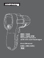
IRC-120
IRC-120-CN
Thermal Camera
with UV and Flashlight
User Manual
ENG FRE SPA
中文


IRC-120
IRC-120-CN
Thermal Camera
with UV and Flashlight
User Manual
5/2018, 6010574 A
©2018 Amprobe
All rights reserved. Printed in Taiwan
English

Limited Warranty and Limitation of Liability
Your Amprobe product will be free from defects in material and workmanship for
one year from the date of purchase unless local laws require otherwise. This warranty
does not cover fuses, disposable batteries or damage from accident, neglect, misuse,
alteration, contamination, or abnormal conditions of operation or handling. Resellers
are not authorized to extend any other warranty on the behalf of Amprobe. To obtain
service during the warranty period, return the product with proof of purchase to an
authorized Amprobe Service Center or to an Amprobe dealer or distributor. See Repair
Section for details. THIS WARRANTY IS YOUR ONLY REMEDY. ALL OTHER WARRANTIES
- WHETHER EXPRESS, IMPLIED OR STATUTORY - INCLUDING IMPLIED WARRANTIES
OF FITNESS FOR A PARTICULAR PURPOSE OR MERCHANTABILITY, ARE HEREBY
DISCLAIMED. MANUFACTURER SHALL NOT BE LIABLE FOR ANY SPECIAL, INDIRECT,
INCIDENTAL OR CONSEQUENTIAL DAMAGES OR LOSSES, ARISING FROM ANY CAUSE
OR THEORY. Since some states or countries do not allow the exclusion or limitation
of an implied warranty or of incidental or consequential damages, this limitation of
liability may not apply to you.
Repair
All Amprobe returned for warranty or non-warranty repair or for calibration should
be accompanied by the following: your name, company’s name, address, telephone
number, and proof of purchase. Additionally, please include a brief description of
the problem or the service requested and include the test leads with the meter. Non-
warranty repair or replacement charges should be remitted in the form of a check, a
money order, credit card with expiration date, or a purchase order made payable to
Amprobe.
In-warranty Repairs and Replacement – All Countries
Please read the warranty statement and check your battery before requesting
repair. During the warranty period, any defective test tool can be returned to your
Amprobe distributor for an exchange for the same or like product. Please check
the “Where to Buy” section on amprobe.com for a list of distributors near you.
Additionally, in the United States and Canada, in-warranty repair and replacement
units can also be sent to an Amprobe Service Center (see address below).
Non-warranty Repairs and Replacement – United States and Canada
Non-warranty repairs in the United States and Canada should be sent to an Amprobe
Service Center. Call Amprobe or inquire at your point of purchase for current repair and
replacement rates.
USA: Canada:
Amprobe Amprobe
Everett, WA 98203 Mississauga, ON L4Z 1X9
Tel: 877-AMPROBE (267-7623) Tel: 905-890-7600
Non-warranty Repairs and Replacement – Europe
European non-warranty units can be replaced by your Beha-Amprobe distributor for a
nominal charge. Please check the “Where to Buy” section on beha-amprobe.com for a list
of distributors near you.
Beha-Amprobe
Division and reg. trademark of Fluke Corp. (USA)
Germany* United Kingdom The Netherlands - Headquarters**
In den Engematten 14 52 Hurricane Way Science Park Eindhoven 5110
79286 Glottertal Norwich, Norfolk 5692 EC Son
Germany NR6 6JB United Kingdom The Netherlands
Phone: +49 (0) 7684 8009 - 0 Phone: +44 (0) 1603 25 6662 Phone: +31 (0) 40 267 51 00
beha-amprobe.de beha-amprobe.com beha-amprobe.com
*(Correspondence only – no repair or replacement available from this address.
European customers please contact your distributor.)
**single contact address in EEA Fluke Europe BV

1
Thermal Camera with UV and Flashlight
CONTENTS
SYMBOLS ............................................................................................3
SAFETY INFORMATION ......................................................................3
UNPACKING AND INSPECTION ..........................................................5
FEATURES AND APPLICATIONS ..........................................................5
BASIC NAVIGATION ............................................................................ 6
MEASUREMENT MODE ......................................................................6
MENU MODE ......................................................................................8
Emissivity .........................................................................................8
UV/Flashlight ................................................................................... 9
Laser Sighting .................................................................................9
Memory/SD Card ............................................................................. 10
Hot and Cold Markers ....................................................................10
Center Point Marker ....................................................................... 11
Color Palette ...................................................................................11
°F / °C ...............................................................................................11
Auto Power OFF ..............................................................................12
Date & Time ....................................................................................12
SPECIFICATIONS ..................................................................................13
MAINTENANCE AND BATTERY REPLACEMENT ................................14

2
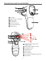
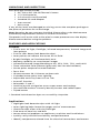
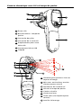
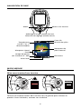
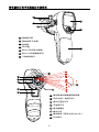
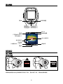
1
LC Display
2
Menu button / Flashlight
3
Battery cover
4
SD card cover
5
Micro SD card slot
6
Micro USB connector
7
Tripod mount
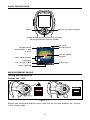
Thermal Camera with UV and Flashlight
1
10
3
2
8
9
5
7
6
13
11
12
15
14
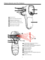
8
Trigger for laser pointer and
image capture
9
Power ON/OFF (Rotary switch)
10
UV light blue LEDs
11
Flashlight LEDs
12
Visual camera
13
Laser aperture
14
Laser sight (Circle/dot/center point)
15
Infrared lens
4

3
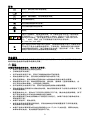
SYMBOLS
W
Caution! Refer to the explanation in this manual.
Consult user documentation.
WARNING! LASER RADIATION. Risk of eye damage.
P
Complies with European Directives.
Conforms to relevant South Korean EMC Standards.
Conforms to relevant Australian standards.
Battery.
Indicates a Class 2 laser. DO NOT STARE INTO BEAM. The
following may appear with the symbol on the product label:
”IEC/EN 60825-1:2014. Complies with 21 CFR 1040.10 and
1040.11 except for deviations pursuant to Laser Notice 50.
Dated June 24, 2007.” In addition, the following pattern on
the label will indicate wavelength and optical power:
λ = xxx nm, x.xx mW.
=
This product complies with the WEEE Directive marking
requirements. The affixed label indicates that you must not
discard this electrical/electronic product in domestic household
waste. Product Category: With reference to the equipment types
in the WEEE Directive Annex I, this product is classed as category
9 “Monitoring and Control Instrumentation” product. Do not
dispose of this product as unsorted municipal waste.
SAFETY INFORMATION
A Warning identifies hazardous conditions and procedures that are
dangerous to the user. A Caution identifies conditions and procedures that
can cause damage to the product or the equipment under test.
Warning
To prevent possible electrical shock, fire, or personal injury:
• Read all safety information before you use the product.
• Carefully read all instructions.
• Use the product only as specified, or the protection supplied by the
product can be compromised.
• Do not use the product around explosive gas, vapor, or in damp or wet
environments.
• Do not look into the laser. Do not point laser directly at persons or
animals or indirectly off reflective surfaces.
• Do not look directly into the laser with optical tools (for example,
binoculars, telescopes, microscopes). Optical tools can focus the laser and
be dangerous to the eye.
• Use the product only as specified, or hazardous laser radiation exposure
can occur.
• Do not use laser viewing glasses as laser protection glasses. Laser viewing
glasses are used only for better visibility of the laser in bright light.

4
• Do not open the product for reasons other than replacing batteries. The
laser beam is dangerous to eyes. Have the product repaired only through
an approved technical site.
• Verify the product’s operation by measuring on a known temperature
source. Do not use the product if it operates incorrectly or abnormally.
• Do not use the product if it is damaged.
• See emissivity information for actual temperatures. Reflective objects
result in lower than actual temperature measurements. These objects
pose a burn hazard.
• Remove the batteries if the product is not used for an extended period of
time, or if stored in temperatures above 122 °F (50 °C). If the batteries are
not removed, battery leakage can damage the product.
• Replace the batteries when the low battery indicator shows to prevent
incorrect measurements.
• Use only AA alkaline batteries and follow all battery care from the
manufacturer.
• Do not leave the product on or near objects of high temperature.
• For use by competent persons only.
• Have an approved technician repair the product.
W Caution
To prevent personal injury and for safe operation and maintenance of the
product:
• Batteries contain hazardous chemicals that can cause burns or explode. If
exposure to chemicals occurs, clean with water and get medical aid.
• Be sure that the battery polarity is correct to prevent battery leakage.
• Do not short the battery terminals together.
• Keep batteries clean and dry.
To avoid damaging the product under measurement, protect it from the
following:
• EMF (electro-magnetic fields) from arc welders and induction heaters.
• Static electricity.
• Thermal shock (caused by large or abrupt ambient temperature changes
— allow 30 minutes for the product to stabilize before use).
• Do not leave the product on or near objects of high temperature.
W
λ
= 650 nm, < 1 mW
Laser aperture

5
UNPACKING AND INSPECTION
Your package should include:
1 IRC-120 or IRC-120-CN Thermal Camera
3 1.5 V AA batteries
1 2 G micro SD card (installed)
1 Standard SD card adapter
1 User manual
1 Wrist strap
If any of the items are damaged or missing, return the complete package to
the place of purchase for an exchange.
Note: Batteries do not come pre-installed. Please refer to the Maintenance
and Battery Replacement section for further instruction.
The product will arrive with a thin plastic screen protector over the display.
Please remove before using the product.
FEATURES AND APPLICATIONS
Features
• Five-in-one: UV light, flashlight, infrared temperature, thermal image and
laser pointer
• Five UV LEDs detect leak detection dyes*
• Laser pointer to indicate the center of UV field
• Bright flashlight to illuminate dark areas
• Memory capability to save thermal images
• Infrared heat map image blending at 0%, 25%, 50%, 75%, and 100%
• Three selectable color palettes (grayscale, hot iron and rainbow)
• Center-point temperature measurement
• Focus free
• IR measurement 20:1 Distance to Spot ratio
• Circle/dot/center point laser sighting
• Adjustable emissivity from 0.10 to 1.00
• Auto off function
• Selectable °F and °C
• Intuitive joystick navigation to on-screen menu and settings
• Hot and cold markers instantly identify hottest and coldest spots
• Tripod mount
* Standard leak detection dyes are not sold by Amprobe.
Applications
• Highlights leak detection dyes with UV light
• Laser sighting helps locate the target area of measurement
• Illuminate dark areas with the flashlight
• Find areas of heat loss and drift
• Locate electrical problems at appliances, machines and installations
• Quickly verify HVAC/R functionality and performance
• Identify temperature related issue for electrical connections and motors

6
BASIC NAVIGATION
Menu Return to measurement
Image blending (measurement mode)
Setting selection (menu mode)
Hot / Cold marker
SD card
Flashlight
(or UV light: UV)
Laser sighting
Temperature
(selectable °F and
°C unit)
Battery level
Emissivity
Center point
marker
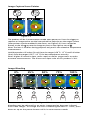
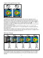
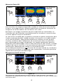
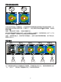
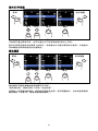
MEASUREMENT MODE
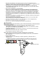
Taking Measurements
Power ON / OFF
Figure 1.1
POWER OFF
Rotate the wheel around the lens to the left to turn the product on. To turn
it off, rotate right.

7
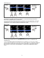
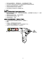
Image Capture/Laser Pointer
Figure 1.2
The product will be in measurement mode upon power on. Press the trigger to
capture an image and to use the laser pointer to help aim on the target surface
(laser pointer must be enabled in the menu, see Figure 2.3). Press navigation
button to the left
to save the image or press to the right to cancel .
Note: The laser is used for aiming purposes only and is not related to temperature
measurement.
Hold the product 12 inches (30 cm) from the target (>59
O
F / 15
O
C) and 2.4 inches
(6 cm) from the target (<59
O
F / 15
O
C) for best temperature accuracy.
Note: Higher Distance to Spot ratios require smaller target areas to make
accurate measurements. The Distance to Spot ratio of this product is 20:1.
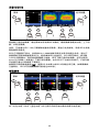
Image Blending
Figure 1.3
0% 25% 50% 75% 100%
UP UP UP UP UP
Blending may be adjusted for an easier interpretation between infrared
and visible images. To change the level of blending between 0 - 100%, press
down or up on the power button while in measurement mode.

8
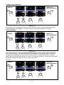
MENU MODE
Changing Settings in the Menu
Once the product is powered on, reach the menu by clicking left on the
power button. Settings that can be manipulated include emissivity, flashlight,
UV light, laser sight, hot and cold markers, center point marker, color palette,
°F/°C, timed auto power off, and date & time.
Enabled options will appear as blue squares while disabled options will
appear as
black squares.
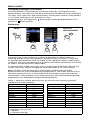
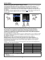
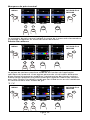
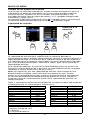
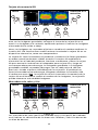
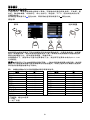
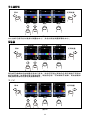
Emissivity
Figure 2.1
DOWN UP
ENTER
MENU BACK TO
MEASUREMENT
The emissivity of the surface of a material describes its effectiveness in
emitting energy as thermal radiation. Quantitatively, emissivity is the ratio
of the thermal radiation from a surface to the radiation from an ideal black
surface at the same temperature as given by the Stefan–Boltzmann law. Refer
to Table 1 for the emissivity adjustment.
In measurement mode, emissivity level is shown on the bottom right of the
screen. Emissivity can be changed to values between 0.10-1.00 in menu.
Note: Surfaces with an emissivity <0.60 make reliable and consistent
determination of actual temperatures problematic. The lower the emissivity,
the more potential error is associated with the temperature measurement
calculations of the product, even when emissivity and reflected background
adjustments are attempted and performed properly.
Table 1. Nominal surface emissivity for an accurate non-contact infrared
temperature measurement.
Material Value Material Value
Default**** 0.95 Glass (plate) 0.85
Aluminum* 0.30 Iron* 0.70
Asbestos 0.95 Lead* 0.50
Asphalt 0.95 Oil 0.94
Brass* 0.50 Paint 0.93
Ceramic 0.95 Plastic** 0.95
Concrete 0.95 Rubber 0.95
Copper* 0.60 Sand 0.90
Food-frozen 0.90 Steel* 0.80
Food-hot 0.93 Water 0.93
Wood*** 0.94
*Oxidized
**Opaque, over 20 mils
***Natural
****Factory Setting

9
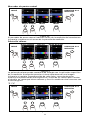
UV/Flashlight
Figure 2.2
DOWN UP ENTER
MENU BACK TO
MEASUREMENT
ENTER
The flashlight can be turned on the the menu or by holding down the
navigator button >2 seconds.
The UV light will illuminate fluorescence in substances and on surfaces. Use
it in combination with UV dyes to inspect automotive and HVAC systems for
leaks.
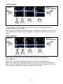
Laser Sighting
Figure 2.3
DOWN UP ENTER
MENU BACK TO
MEASUREMENT
ENTER
Laser sighting provides an accurate visual target for temperature
measurement.
*See SAFETY INFORMATION on pages 3 to 4 when using the laser.
Once laser sighting is enabled on menu, return to measurement mode by
pressing the navigator button to the right, and press the trigger to activate
laser sighting (see page 7: Image Capture/Laser Pointer).

10
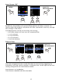
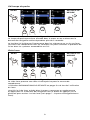
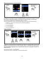
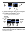
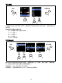
Memory/SD Card
Figure 2.4
DOWN UP DOWN UPENTER
MENU BACK TO
MEASUREMENT
To view saved images, navigate to the SD card icon in the menu. Most recent
images will appear first. Browse images by toggling up or down.
Note: Images cannot be deleted or renamed through the IRC-120 interface.
Make these modifications by installing the SD card in an alternate device such
as a computer.
The SD card comes installed in the product and will name saved photos in
numerical order from 0001-9999. Access the SD card through the movable
flap on the side of the product. Gently push on and release the SD card to
pop it out. Insert it into the SD card adapter and then into a computer to
download saved images. Saved images can also be downloaded with a micro
B USB cable (not supplied). Access the USB port below the SD card. The
product does not need to be powered on to download pictures through the
USB connection.
If you receive this error (
), either the SD card is not inserted or SD card
memory is full. If the images are renamed, the SD card may be able to store
more than 9,999 images.
Hot and Cold Markers
Figure 2.5
DOWN UP ENTER
MENU BACK TO
MEASUREMENT
ENTER
Hot (red square outline) and cold (blue square outline) markers indicate the
locations of hottest and coldest areas within a target area.

11
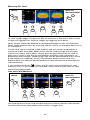
Center Point Marker
DOWN UP ENTER
MENU BACK TO
MEASUREMENT
ENTER
Figure 2.6
The center point marker indicates the center of the infrared thermometer
measurement and appears in the center of the measurement screen.
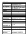
Color Palette
DOWN UP ENTER
MENU BACK TO
MEASUREMENT
ENTER
GrayscaleRainbow
Hot Iron
Figure 2.7
The color palette can be changed depending on the specific application of
the measurement. This option allows for different viewings of an infrared
image by changing the false-color presentation. Grayscale shows a more
equal and linear presentation of colors to enhance detail, while Hot Iron and
Rainbow combine high contrast with Grayscale.
°F / °C
DOWN UP ENTER
MENU BACK TO
MEASUREMENT
ENTER
Figure 2.8

12
Auto Power OFF
DOWN UP
ENTER
MENU BACK TO
MEASUREMENT
Figure 2.9
By default, the product will automatically power off after 1 minute. To
choose when the product will power off after a period of inactivity, change
the settings in the menu.
Available options for the Auto Power Off setting:
• OFF (the camera will not turn off automatically)
• 1 m (1 minute)
• 2 m (2 minutes)
• 5 m (5 minutes)
• 10 m (10 minutes)
Date & Time
DOWN UP ENTER
MENU BACK TO
MEASUREMENT
ENTER
Figure 2.10
Press the navigator button to edit the date or time setting, toggling up
and down until the correct number is selected. Press to the right to exit the
setting and go back to measurement mode.
Date format: YYYY/MM/DD
Time format: AM/PM and 24h selectable

13
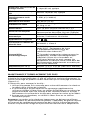
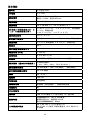
SPECIFICATIONS
UV light
5 blue LEDs
Flashlight
4 LEDs
Laser sighting
Circle/dot/center point laser
Output <1 mW, wavelength 650 nm
Temperature measurement
Yes, center point
Temperature range
14 °F to 932 °F (-10 °C to 500 °C)
IR accuracy (calibration
geometry with ambient
temperature 23°C ± 2°C)
≥ 32 °F (≥ 0 °C): ± 4 °F (± 2 °C) or ± 2 % of the
reading, whichever is greater
< 32 °F (< 0 °C): ± 6 °F (± 3 °C)
Display resolution
0.2 °F / 0.1 °C
IR Repeatability
± 0.8 % of the reading or ± 2 °F (± 1 °C),
whichever is greater
Temperature Coefficient
0.1 °C/°C or ± 0.1 %/°C of the reading,
whichever is greater
Distance to spot
20:1
Minimum spot size
8 mm
Response time (95 %)
< 125 ms
Spectral response
8 μm to 14 μm
Emissivity
Digitally adjustable from 0.10 to 1.00 by 0.01
Visual image with infrared
heat map overlay
Five blending modes
(0%, 25%, 50%, 75% and 100%)
Visual image resolution
16,384 pixels (128 x 128 pixels)
(Interpolation pixels)
IR detector resolution
32 x 32 pixels
Field of view
33 ° x 33 °
Thermal sensitivity
150 mK
Focus system
Focus free
Image palettes
Grayscale (white hot), Hot Iron and Rainbow
Hot and cold marker
Yes
Center point marker
Yes
Display
1.77 in color TFT with 128 x 160 pixels
Data storage
Stored image size: 124 x 160 pixels
Image file size: typical 40 KB
Maximum stored images: 9999
Operating temperature
and humidity
32 °F to 122 °F (0 °C to 50 °C)
10 % to 90 % RH non-condensing at 86 °F (30 °C)
Storage temperature
-4 °F to 140 °F (-20 °C to 60 °C) without
batteries

14
Visual to IR effective image
alignment
≥ 18 inches (45 cm), optimal for 1 m
Laser sighting to center of
visual image
≥ 18 in (45 cm) typical
Laser sighting to UV field
Approx. 18 in (45 cm) typical
Operating and storage
altitude
< 6561 ft (< 2000 m)
Drop proof
4 ft (1.2 m)
Vibration and shock
IEC 60068-2-6, 2.5g, 10 to 200 Hz, IEC 60068-2-
27, 50g 11ms
Power supply
Three (3) 1.5 V AA IEC LR6 alkaline batteries
Battery life
8 hours with display ON (Typical)
Power consumption: 220 mA (Typical)
Auto power off
Selectable modes: OFF, 1 minute, 2 minutes, 5
minutes and 10 minutes
Agency approvals
P
Laser safety compliance
IEC 60825-1, Class 2
Electromagnetic
Compatibility
EN 61326-1
Korea (KCC): Class A Equipment (Industrial
Broadcasting & Communication Equipment)
[1]
[1]
This product meets requirements for
industrial (Class A) electromagnetic wave
equipment and the seller or user should take
notice of it. This equipment is intended for
use in business environments and is not to be
used in homes.
Size (H x W x L)
Approx. 7.3 x 2.1 x 4.1 in (185 x 54 x 104 mm)
Weight
Approx. 0.64 lb (0.29 kg)
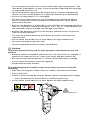
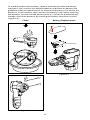
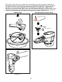
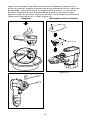
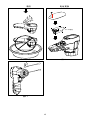
MAINTENANCE AND BATTERY REPLACEMENT
Do not use abrasives, isopropyl alcohol, or solvents to clean the case or lens/
window. If used and stored properly, the infrared lens on the product should
require only occasional cleaning (Figure 3.1).
When necessary, to clean the lens:
1. Use a hand-squeeze air pump to gently blow off any dust or debris from
the lens surface.
2. If the lens surface requires additional cleaning, use a clean, fine-fiber cloth,
micro-fiber cloth, or cotton swab dampened with a mild, soapy water
solution. Gently wipe surface of lens to remove smudges and debris.
3. Dry with an absorbent, clean fine-fiber or micro-fiber cloth.
Note: Minor smudges and dirt should not significantly affect the performance
of the product. However, large scratches or the removal of the protective
coating on the infrared lens can affect both image quality and the
temperature measurement accuracy.

15
To avoid incorrect measurements, replace the batteries when the battery
indicator is low. Use only AA alkaline batteries and follow all battery care
guidelines from the manufacturer. To remove the batteries, first ensure the
product is in OFF position, then unscrew the battery cover. When installing
the batteries, be sure that the battery polarity is correct to prevent battery
leakage. Secure the batteries by screwing the battery cover back in place
(Figure 3.2).
Figure 3.1
Clean
Figure 3.2
3 x AA batteries
Battery Replacement

16
ページが読み込まれています...
ページが読み込まれています...
ページが読み込まれています...
ページが読み込まれています...
ページが読み込まれています...
ページが読み込まれています...
ページが読み込まれています...
ページが読み込まれています...
ページが読み込まれています...
ページが読み込まれています...
ページが読み込まれています...
ページが読み込まれています...
ページが読み込まれています...
ページが読み込まれています...
ページが読み込まれています...
ページが読み込まれています...
ページが読み込まれています...
ページが読み込まれています...
ページが読み込まれています...
ページが読み込まれています...
ページが読み込まれています...
ページが読み込まれています...
ページが読み込まれています...
ページが読み込まれています...
ページが読み込まれています...
ページが読み込まれています...
ページが読み込まれています...
ページが読み込まれています...
ページが読み込まれています...
ページが読み込まれています...
ページが読み込まれています...
ページが読み込まれています...
ページが読み込まれています...
ページが読み込まれています...
ページが読み込まれています...
ページが読み込まれています...
ページが読み込まれています...
ページが読み込まれています...
ページが読み込まれています...
ページが読み込まれています...
ページが読み込まれています...
ページが読み込まれています...
ページが読み込まれています...
ページが読み込まれています...
ページが読み込まれています...
ページが読み込まれています...
ページが読み込まれています...
ページが読み込まれています...
ページが読み込まれています...
ページが読み込まれています...
ページが読み込まれています...
ページが読み込まれています...
ページが読み込まれています...
ページが読み込まれています...
-
 1
1
-
 2
2
-
 3
3
-
 4
4
-
 5
5
-
 6
6
-
 7
7
-
 8
8
-
 9
9
-
 10
10
-
 11
11
-
 12
12
-
 13
13
-
 14
14
-
 15
15
-
 16
16
-
 17
17
-
 18
18
-
 19
19
-
 20
20
-
 21
21
-
 22
22
-
 23
23
-
 24
24
-
 25
25
-
 26
26
-
 27
27
-
 28
28
-
 29
29
-
 30
30
-
 31
31
-
 32
32
-
 33
33
-
 34
34
-
 35
35
-
 36
36
-
 37
37
-
 38
38
-
 39
39
-
 40
40
-
 41
41
-
 42
42
-
 43
43
-
 44
44
-
 45
45
-
 46
46
-
 47
47
-
 48
48
-
 49
49
-
 50
50
-
 51
51
-
 52
52
-
 53
53
-
 54
54
-
 55
55
-
 56
56
-
 57
57
-
 58
58
-
 59
59
-
 60
60
-
 61
61
-
 62
62
-
 63
63
-
 64
64
-
 65
65
-
 66
66
-
 67
67
-
 68
68
-
 69
69
-
 70
70
-
 71
71
-
 72
72
-
 73
73
-
 74
74


他の言語で
その他のドキュメント
-
Fluke Calibration 2700G 取扱説明書
-
-
Dell Canvas 27 ユーザーガイド
-
Philips DCTG5500G/93 Product Datasheet
-
-
-
-
-
Bosch GTC 400 C Professional ユーザーマニュアル
-