
USER GUIDE
EZ Switch
TM
10/100/1000
8-Port Gigabit Ethernet Switch
SMCGS805

No. 1, Creation Road III,
Hsinchu Science Park,
30077, Taiwan, R.O.C.
TEL: +886 3 5638888
Fax: +886 3 6686111
EZ Switch
TM
10/100/1000
User Guide
From SMC’s EZ line of low-cost workgroup LAN solutions
March 2014
E032014-AP-R01

Information furnished by SMC Networks, Inc. (SMC) is believed to be accurate
and reliable. However, no responsibility is assumed by SMC for its use, nor for
any infringements of patents or other rights of third parties which may result
from its use. No license is granted by implication or otherwise under any patent
or patent rights of SMC. SMC reserves the right to change specifications at any
time without notice.
Copyright © 2014 by
SMC Networks, Inc.
No. 1, Creation Road III,
Hsinchu Science Park,
30077, Taiwan, R.O.C.
All rights reserved
Trademarks:
SMC is a registered trademark; and EZ Switch, TigerStack and TigerSwitch are
trademarks of SMC Networks, Inc. Other product and company names are
trademarks or registered trademarks of their respective holders.

– 4 –
W
ARRANTY
AND
P
RODUCT
R
EGISTRATION
To register SMC products and to review the detailed warranty statement, please
refer to the Support Section of the SMC Website at http://www.smc.com.

– 5 –
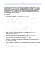
COMPLIANCES AND SAFETY
STATEMENTS
FEDERAL COMMUNICATION COMMISSION INTERFERENCE STATEMENT
This equipment has been tested and found to comply with the limits for a Class A
digital device, pursuant to Part 15 of the FCC Rules. These limits are designed to
provide reasonable protection against harmful interference when the equipment
is operated in a commercial environment. This equipment generates, uses, and
can radiate radio frequency energy and, if not installed and used in accordance
with the instruction manual, may cause harmful interference to radio
communications. Operation of this equipment in a residential area is likely to
cause harmful interference, in which case the user will be required to correct the
interference at his own expense.
Properly shielded and grounded cables and connectors must be used in order to
meet FCC emission limits. SMC is not responsible for any radio or television
interference caused by using other than recommended cables and connectors or
by unauthorized changes or modifications to this equipment. Unauthorized
changes or modifications could void the user's authority to operate the
equipment.
This device complies with Part 15 of the FCC rules. Operation is subject to the
following two conditions:
◆ This device may not cause harmful interference.
◆ This device must accept any interference received, including interference
that may cause undesired operation.
CE MARK DECLARATION OF CONFORMANCE FOR EMI AND SAFETY (EEC)
This is a class A product. In a domestic environment, this product may cause
radio interference, in which case the user may be required to take adequate
measures.
Declaration of Conformity (DoC) can be obtained from www.smc.com -> support
-> download

C
OMPLIANCES
AND
S
AFETY
S
TATEMENTS
– 6 –
This information technology equipment complies with the requirements of the
Council Directive 2004/108/EC on the Approximation of the laws of the Member
States relating to Electromagnetic Compatibility and 2006/95/EC for electrical
equipment used within certain voltage limits and the Amendment Directive
2006/95/EC. For the evaluation of the compliance with these Directives, the
following standards were applied:
RFI Emission:
◆ Limit class A according to EN 55022: 2010 (EMC)
◆ Limit class A for harmonic current emission according to EN 61000-3-
2:2006 + A1:2009 + A2: 2009
◆ Limitation of voltage fluctuation and flicker in low-voltage supply system
according to EN 61000-3-3:2008
Immunity:
◆ Product family standard according to EN 55024:2010
◆ Electrostatic Discharge according to IEC 61000-4-2: 2008
◆ Radio-frequency electromagnetic field according to IEC 61000-4-3:
2006+A1:2007+A2:2010
◆ Electrical fast transient/burst according to IEC 61000-4-4: 2012
◆ Surge immunity test according to IEC 61000-4-5: 2005
◆ Immunity to conducted disturbances, Induced by radio-frequency fields:
IEC 61000-4-6: 2008
◆ Power frequency magnetic field immunity test according to IEC 61000-4-8:
2009
◆ Voltage dips, short interruptions and voltage variations immunity test
according to IEC 61000-4-11: 2004

C
OMPLIANCES
AND
S
AFETY
S
TATEMENTS
– 7 –
LVD:
◆ EN 60950-1:2006+A11:2009+A1:2010 + A12:2011
CE MARK WARNING
This equipment complies with the requirements relating to electromagnetic
compatibility, EN 55022 class A for ITE, the essential protection requirement of
Council Directive 2004/108/EC on the approximation of the laws of the Member
States relating to electromagnetic compatibility.
SMC has an on-going policy of upgrading its products and it may be possible that
information in this document is not up-to-date. Please check with your local
distributors for the latest information. No part of this document can be copied or
reproduced in any form without written consent from SMC.
BSMI (TAIWAN)
警告使用者 : 此為甲類資訊技術設備,於居住環境中使用時,可能會造成射頻擾動,在此種
情況下,使用者會被要求採取某些適當的對策。
電氣方面的安全性
◆ 為避免可能的電擊造成嚴重損害,再搬動產品之前,請先將產品電源線暫時從電源插座
中拔掉。
◆ 當您要加入硬體裝置到系統中或者要移除系統中的硬體裝置時,請務必先連接該裝置的
訊號線,然後再連接電源線。可能的話,在安裝硬體裝置之前先拔掉產品的電源供應器
電源線。
◆ 當您要從主機板連接或拔除任何的訊號線之前,請確定所有電源線已事先拔掉。
◆ 請確定電源供應器的電壓設定已調到本國 / 本區域所使用的電壓標準。若您不確定您所
屬區域的供應電壓為何,那麼請就近詢問當地的電力公司人員。
◆ 如果電源供應器已損壞,請不要嘗試自行修復。請將之交給專業技術服務人員或經銷商
來處理。
操作方面的安全性
◆ 在使用產品之前,請確定所有的排線、電源線都已正確地連接好。若您發現有重大的瑕
疵,請盡速連絡您的經銷商。

C
OMPLIANCES
AND
S
AFETY
S
TATEMENTS
– 8 –
◆ 為避免發生電氣短路情形,請務必將所有沒用到的螺絲、迴紋針及其他零件收好,不要
遺留在主機板上或產品主機中。
◆ 灰塵、溼氣以及劇烈的溫度變化都會影響主機板的使用壽命,因此請盡量避免放置在這
些地方。
◆ 請勿將產品主機放置在容易搖晃的地方。
◆ 若在本產品的使用上有任何的技術性問題,請和經過檢定或有經驗的技術人員聯絡。
使用注意事項
◆ 在您開始操作本系統之前,請務必詳閱以下注意事項,以避免因為人為的疏失造成系統
損傷甚至人體本身的安全。
◆ 使用前,請檢查產品各部份組件是否正常,以及電源線是否有任破損,或是連接不正確
的情形發生。
◆ 如果有任何破損情形,請盡速與您的授權經銷商連絡,更換良好的線路。
◆ 產品放置的位置請遠離灰塵過多,溫度過高,太陽直射的地方。
◆ 保持機器在乾燥的環境下使用,雨水、溼氣、液體等含有礦物質將會腐蝕電子線路。
◆ 使用時,請務必保持周遭散熱空間,以利散熱。
◆ 使用前,請檢查各項周邊設備是否都已經連接妥當再開機。
◆ 避免邊吃東西邊使用,以免污染機件造成故障。
◆ 請避免讓紙張碎片、螺絲及線頭等小東西靠近產品之連接器、插槽、孔位等處,避免短
路及接觸不良等情況發生。
◆ 請勿將任何物品塞入產品內,以避免引起機件短路或電路損毀。
◆ 產品開機一段時間之後,散熱片及部份 IC 表面可能會發熱、發燙,請勿用手觸摸,並
請檢查系統是否散熱不良。
◆ 在安裝或移除周邊產品時請先關閉電源。
◆ 電源供應器如果發生損壞,切勿自行修理,請交由授權經銷商處理。

C
OMPLIANCES
AND
S
AFETY
S
TATEMENTS
– 9 –
◆ 產品的機殼、鐵片大部份都經過防割傷處理,但是您仍必須注意避免被某些細部鐵片尖
端及邊緣割傷,拆裝機殼時最好能夠戴上手套。
當你有一陣子不使用產品時,休假或是颱風天,請關閉電源之後將電源線拔掉。

– 10 –
ABOUT THIS GUIDE
PURPOSE
This guide details the hardware features of the switch, including the physical and
performance-related characteristics, and how to install the switch.
AUDIENCE
The guide is intended for use by network administrators who are responsible for
installing and setting up network equipment; consequently, it assumes a basic
working knowledge of LANs (Local Area Networks).
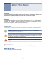
CONVENTIONS
The following conventions are used throughout this guide to show information:
REVISION HISTORY
This section summarizes the changes in each revision of this guide.
MARCH 2014 REVISION
This is the first revision of this guide.
N
OTE
:
Emphasizes important information or calls your attention to
related features or instructions.
C
AUTION
:
Alerts you to a potential hazard that could cause loss of data,
or damage the system or equipment.
W
ARNING
:
Alerts you to a potential hazard that could cause personal
injury.

– 11 –
CONTENTS
WARRANTY AND PRODUCT REGISTRATION 4
C
OMPLIANCES AND SAFETY STATEMENTS 5
A
BOUT THIS GUIDE 10
C
ONTENTS 11
1I
NTRODUCTION 13
Overview 13
Package Contents 13
Features 14
IEEE 802.1p QoS 15
Loopback Detection and Prevention 16
Private VLAN Support 17
2HARDWARE DESCRIPTION 18
Port and System Status LEDs 18
Installation 19
PC Connections 19
Switch Connections 19
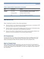
ATROUBLESHOOTING 21
Diagnosing Switch Indicators 21
The PWR LED is Off 21
The Link/Act LED is Off when a Device is Connected to the Corre-
sponding Port 21
Power and Cooling Problems 21
Installation 22
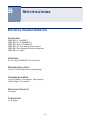
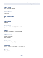
BSPECIFICATIONS 23


– 13 –
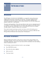
1 INTRODUCTION
OVERVIEW
The EZ Switch 10/100/1000, SMCGS805, is a powerful, high-performance
Gigabit Ethernet switch with eight RJ-45 ports. The switch supports auto-
negotiation on all ports, which means they automatically negotiate with
connected partners to determine the network speed (10/100/1000 Mbps) and
duplex mode (full or half duplex).
The auto-sensing ability of the ports provides an easy way to migrate from 10/
100 Mbps to a 1000 Mbps network. The switch also supports Auto-MDI/ MDIX,
so each port can be connected to PCs or other switches using only straight-
through cables. Crossover cables are not needed.
Store-and-forward switching provides low latency while eliminating error
packets on the network. Also, the switch supports pre-standard IEEE 802.3az
Energy Efficient Ethernet that saves power consumption.
PACKAGE CONTENTS
Before installing the switch, verify that you have all the items listed in the
package contents. If any of the items are missing or damaged, contact your
local SMC distributor. Also be sure you have all the necessary tools and cabling
before installing the switch.
The following contents should be found in your package:
◆ One SMCGS805 switch
◆ One external power adapter
◆ Wall mount Kit
◆ This User Guide

C
HAPTER
1
| Introduction
Package Contents
– 14 –
◆ SMC Warranty Card
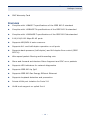
FEATURES
◆ Complies with 10BASE-T specifications of the IEEE 802.3 standard
◆ Complies with 100BASE-TX specifications of the IEEE 802.3u standard
◆ Complies with 1000BASE-T specifications of the IEEE 802.3ab standard
◆ 8 10/100/1000 Mbps RJ-45 ports
◆ Supports MDI/MDI-X auto crossover
◆ Supports full- and half-duplex operation on all ports
◆ Supports back-pressure (half duplex) and full-duplex flow control (IEEE
802.3x)
◆ Wire-speed packet filtering and forwarding rate
◆ Store-and-forward architecture filters fragment and CRC error packets
◆ Supports LED indicators for network diagnostics
◆ Supports IEEE 802.1p QoS
◆ Supports IEEE 802.3az Energy-Efficient Ethernet
◆ Supports loopback detection and prevention
◆ Private VLAN port isolation for Ports 2-8
◆ VLAN trunk support on uplink Port 1

C
HAPTER
1
| Introduction
Package Contents
– 15 –
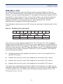
IEEE 802.1P QOS
The SMCGS805 switch supports 802.1p priority queuing Quality of Service,
which is an implementation of the IEEE 802.1p standard. With the 802.1p QoS
function, you can reserve bandwidth for important functions that require a lot of
bandwidth or have a high priority, such as VoIP (Voice-over Internet Protocol),
web browsing applications, or video conferencing. The switch has separate
hardware queues on each physical port to which packets from various
applications are mapped and priorities assigned.
The illustration below shows how 802.1p priority queuing is implemented on the
switch.
Figure 1: Mapping QoS on the Switch
There are four priority queues labeled TC0, TC1, TC2 and TC3. The untagged
packets and the eight IEEE 802.1p priority values (defined by the standard) are
mapped to the four priority queues on the switch. TC3 has the highest priority of
the four priority queues, while TC0 has the lowest priority. The untagged packets
and eight priority values, specified in IEEE 802.1p, are mapped to the switch’s
priority queues as follows:
◆ Untagged packets, and packets with priority 1 and 2 are assigned to the
switch’s TC0 queue.
◆ Packets with priority 0 and 3 are assigned to the switch’s TC1 queue.
◆ Packets with priority 4 and 5 are assigned to the switch’s TC2 queue.
◆ Packets with priority 6 and 7 are assigned to the switch’s TC3 queue.
The switch uses Weighted Robin Round (WRR) for scheduling. The WRR queue-
scheduling algorithm schedules all the queues in turn with every queue assured
a certain service time. For WRR mode, the default weight values of TC0, TC1,
TC2 and TC3 are 1:2:4:8.
Tag untag 0 1 2 3 4 5 6 7
Priority Queue
Weight Value 1 2 4 8
TC0 TC1 TC2 TC3

C
HAPTER
1
| Introduction
Package Contents
– 16 –
LOOPBACK DETECTION AND PREVENTION
When a loop occurs at a port, the switch will
■
Block the loop port, automatically protecting the switch.
■
Flash the port LED twice every second.
■
Turn the Loop LED on red.
When the loop clears the port LED will cease flashing and the Loop LED will turn
off.
Figure 2: Loopback Detection and Prevention

C
HAPTER
1
| Introduction
Package Contents
– 17 –
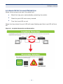
PRIVATE VLAN SUPPORT
The switch is designed for Internet access deployment where subscriber end
nodes are connected to an Internet Service Provider network through the
switch. In this application, each port is isolated in its own private VLAN to
provide security for each end user, only the uplink port (Port 1) can
communicate with all other ports. Ports 2-8 cannot communicate with each
other.
The switch ports each have a fixed default VLAN ID, with Port 1 fixed as a VLAN
trunk port. The figure below indicates the VLAN IDs assigned to each switch
port. Note that Port 1 is the uplink port and must be connected to a switch or
router in the service provider network.
Figure 3: Private VLAN Configuration

– 18 –
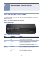
2 HARDWARE DESCRIPTION
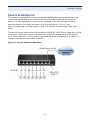
PORT AND SYSTEM STATUS LEDS
The switch contains one power LED, one loop LED for the device, and Link/Act
LEDs for each port.
Refer to the following table for LED definitions:
Figure 4: Front Panels
Table 1: System and Port Status LEDs
LED Condition Status
PWR On Green The internal power supply is operating normally.
Off The unit has no power connected.
LOOP On Red The switch has detected a loop condition and
disabled the appropriate port. When the loop
clears, the LED will turn off.
Off The switch has not detected a loop condition or
the current loop condition has cleared.
Link/Act
(10/100M)
On Green Port has established a valid 10/100 Mbps network
connection. Flashing indicates activity.
Flashing Green Flashing indicates activity.
Off There is no valid link on the port.

C
HAPTER
2
| Hardware Description
Installation
– 19 –
INSTALLATION
When installing the switch, follow these guidelines:
◆ Place the switch in an appropriate ventilated environment. A minimum of 25
mm space around the unit is recommended.
◆ Place the switch and connected cables away from sources of electrical noise,
such as radios, transmitters, and broadband amplifiers.
◆ Be sure the switch is placed away from moisture and locations that do not
conform to its recommended environmental specifications.
PC CONNECTIONS
Connect each PC to the switch using twisted-pair Ethernet cables with RJ-45
connectors at each end. Plug one RJ-45 connector into an RJ-45 port on the
switch, and plug the other RJ-45 connector into a PC's network port.
SWITCH CONNECTIONS
When making switch interconnections, you can use any port on the switch to
connect to another switch using straight-through or crossover cable. As all ports
on the switch support Auto MDI/MDIX, you can use straight-through cables for
all connections.
Link/Act
(1000M)
On Amber Port has established a valid 1000 Mbps network
connection. Flashing indicates activity.
Flashing Amber Flashing indicates activity.
Off There is no valid link on the port.
Table 1: System and Port Status LEDs (Continued)
LED Condition Status

C
HAPTER
2
| Hardware Description
Installation
– 20 –
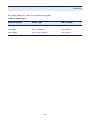
For cable selection, refer to the following table.
Table 2: Cable Types
Network Speed Cable Type Max. Length
10 Mbps Cat. 3, 4, 5 UTP/STP 100 meters
100 Mbps Cat. 5 UTP/STP 100 meters
1000 Mbps Cat. 5e, 6 UTP/STP 100 meters
ページが読み込まれています...
ページが読み込まれています...
ページが読み込まれています...
ページが読み込まれています...
ページが読み込まれています...
ページが読み込まれています...
ページが読み込まれています...
ページが読み込まれています...
-
 1
1
-
 2
2
-
 3
3
-
 4
4
-
 5
5
-
 6
6
-
 7
7
-
 8
8
-
 9
9
-
 10
10
-
 11
11
-
 12
12
-
 13
13
-
 14
14
-
 15
15
-
 16
16
-
 17
17
-
 18
18
-
 19
19
-
 20
20
-
 21
21
-
 22
22
-
 23
23
-
 24
24
-
 25
25
-
 26
26
-
 27
27
-
 28
28


