Hitachi Power Screwdriver W 6V4 ユーザーマニュアル
- カテゴリー
- パワーツール
- タイプ
- ユーザーマニュアル

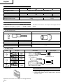
W 6VM • W 6V4 • W 6VA4 • W 6VB3 • W 8VB2
HANDLING INSTRUCTION
使用說明書
Screw Driver
日立牌電動起子機
Read through carefully and understand these instructions before use.
使用前務請詳加閱讀
W6VM • W6V4 • W6VA4
W6VB3 • W8VB2

1
12
4
6
8
3
5
7
L
R
2
1
3
4
5
6 9
7 D
8 D
:
9
A
B C
D
B E
1 - 1.5 mm
1 - 1.5 mm
1.5 - 2 mm

2
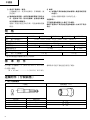
Lever
R side
Sub-Stopper (B)
Locator
Gear cover
Hex. head screw
Drywall screw
Self-drilling screw
Sub-Stopper (B)
Magnetic hex. socket
Sub-Stopper (G)
Bit
Bit holder (Short type)
Sub-Stopper (F)
Bit holder
1
2
3
4
5
6
7
8
9
@
A
B
C
D
E
拉杆
R 側
副制動器 (B)
定位器
齒輪罩
六腳頭螺絲
清水牆螺絲
自鑽螺絲
副制動器 (B)
磁性六腳座
副制動器 (G)
鑽頭
鑽頭座(短型)
副制動器 (F)
鑽頭座

3
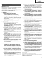
English
GENERAL SAFETY RULES
WARNING!
Read all instructions
Failure to follow all instructions listed below may result
in electric shock, fire and/or serious injury.
The term “power tool” in all of the warnings listed below
refers to your mains operated (corded) power tool or
battery operated (cordless) power tool.
SAVE THESE INSTRUCTIONS
1) Work area
a) Keep work area clean and well lit.
Cluttered and dark areas invite accidents.
b) Do not operate power tools in explosive
atmospheres, such as in the presence of
flammable liquids, gases or dust.
Power tools create sparks which may ignite the
dust of fumes.
c) Keep children and bystanders away while
operating a power tool.
Distractions can cause you to lose control.
2) Electrical safety
a) Power tool plugs must match the outlet.
Never modify the plug in any way.
Do not use any adapter plugs with earthed
(grounded) power tools.
Unmodified plugs and matching outlets will
reduce risk of electric shock.
b) Avoid body contact with earthed or grounded
surfaces such as pipes, radiators, ranges and
refrigerators.
There is an increased risk of electric shock if your
body is earthed or grounded.
c) Do not expose power tools to rain or wet
conditions.
Water entering a power tool will increase the risk
of electric shock.
d) Do not abuse the cord. Never use the cord for
carrying, pulling or unplugging the power tool.
Keep cord away from heat, oil, sharp edges or
moving parts.
Damaged or entangled cords increase the risk of
electric shock.
e) When operating a power tool outdoors, use an
extension cord suitable for outdoor use.
Use of a cord suitable for outdoor use reduces the
risk of electric shock
3) Personal safety
a) Stay alert, watch what you are doing and use
common sense when operating a power tool.
Do not use a power tool while you are tired or
under the influence of drugs, alcohol or medication.
A moment of inattention while operating power
tools may result in serious personal injury.
b) Use safety equipment. Always wear eye protection.
Safety equipment such as dust mask, non-skid
safety shoes, hard hat, or hearing protection used
for appropriate conditions will reduce personal
injuries.
c) Avoid accidental starting. Ensure the switch is in
the off position before plugging in.
Carrying power tools with your finger on the
switch or plugging in power tools that have the
switch on invites accidents.
d) Remove any adjusting key or wrench before
turning the power tool on.
A wrench or a key left attached to a rotating part
of the power tool may result in personal injury.
e) Do not overreach. Keep proper footing and
balance at all times.
This enables better control of the power tool in
unexpected situations.
f) Dress properly. Do not wear looses clothing or
jewellery. Keep your hair, clothing and gloves
away from moving parts.
Loose clothes, jewellery or long hair can be caught
in moving parts.
g) If devices are provided for the connection of dust
extraction and collection facilities, ensure these
are connected and properly used.
Use of these devices can reduce dust related hazards.
4) Power tool use and care
a) Do not force the power tool. Use the correct
power tool for your application.
The correct power tool will do the job better and
safer at the rate for which it was designed.
b) Do not use the power tool if the switch does not
turn it on and off.
Any power tool that cannot be controlled with the
switch is dangerous and must be repaired.
c) Disconnect the plug from the power source before
making any adjustments, changing accessories,
or storing power tools.
Such preventive safety measures reduce the risk
of starting the power tool accidentally.
d) Store idle power tools out of the reach of children
and do not allow persons unfamiliar with the
power tool or these instructions to operate the
power tool.
Power tools are dangerous in the hands of
untrained users.
e) Maintain power tools. Check for misalignment or
binding of moving parts, breakage of parts and
any other condition that may affect the power
tools operation.
If damaged, have the power tool repaired before
use.
Many accidents are caused by poorly maintained
power tools.
f) Keep cutting tools sharp and clean.
Properly maintained cutting tools with sharp cutting
edges are less likely to bind and are easier to control.
g) Use the power tool, accessories and tool bits
etc., in accordance with these instructions and in
the manner intended for the particular type of
power tool, taking into account the working
conditions and the work to be performed.
Use of the power tool for operations different from
intended could result in a hazardous situation.
5) Service
a) Have your power tool serviced by a qualified repair
person using only identical replacement parts.
This will ensure that the safety of the power tool
is maintained.
PRECAUTION
Keep children and infirm persons away.
When not in use, tools should be stored out of reach of
children and infirm persons.

4
English
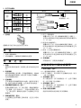
OPTIONAL ACCESSORIES (sold separately)
1. For hex-head screws
STANDARD ACCESSORIES
(1)
No. 2 Plus bit .............................. 1(W6VM, W6V4, W6VA4)
(2)
Magnetic hex socket (H = 10 mm) ....... 1 (W6VB3, W8VB2)
Standard accessories are subject to change without
notice.
Magnetic bit holder
(Short type)
Magnetic bit holder
Non-magnetic bit bolder
Hex-socket Sub-Stopper (B)
Magnetic type
H = 6.35 mm
H = 7.94 mm
H = 9.53 mm
H = 10 mm
Non magnetic type
H = 6.35 mm
H = 7.94 mm
H = 9.53 mm
H = 10 mm
H 1/4
H 5/16
H 3/8
Bit type Sub-Stopper
2. For other screws
Bit holder
Screw
head
No.1
No.2
No.3
No.1
No.2
No.1
No.2
No.3
No.1
No.2
B Size
4 mm
5 mm
Sub-Stopper (G)
Sub-Stopper (F)
SPECIFICATIONS
Model W6VM W6V4 W6VA4 W6VB3 W8VB2
Voltage (by areas)* (110V, 115V, 120V, 127V, 220V, 230V, 240V)
Power input 620 W
No-load speed 0 – 6000/min 0 – 4500/min 0 – 3000/min 0 – 2600/min 0 – 1700/min
Capacities 6 mm 8 mm
Bit shank size 6.35 mm Hex.
Weight (without cord) 1.4 kg 1.5 kg
* Be sure to check the nameplate on product as it is subject to change by areas.
3. Plastic case
Optional accessories are subject to change without
notice.
APPLICATIONS
䡬 Tightening hex-head screws.
䡬 Tightening drywall screws, wood screws and self-
drilling screws.

5
English
PRIOR TO OPERATION
1. Power source
Ensure that the power source to be utilized conforms
to the power requirements specified on the product
nameplate.
2. Power switch
Ensure that the power switch is in the OFF position. If
the plug is connected to a power receptacle while the
power switch is in the ON position, the power tool
will start operating immediately, which could cause a
serious accident.
3. Extension cord
When the work area is removed from the power
source, use an extension cord of sufficient thickness
and rated capacity. The extension cord should be
kept as short as practicable.
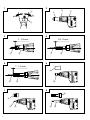
4. Confirm the direction of bit rotation (Fig. 1)
The bit rotates clockwise (viewed from the rear side)
when the reversing switch lever is set to the “R” side
position. When the lever is set to the “L” side position,
the bit rotates counterclockwise and can be used to
loosen and remove screws.
5. Adjusting the tightening depth (Fig. 2)
The tightening depth can be adjusted by turning
locator right and left click feeling.
(1) For hex-head screws:
Mount a hex-head screw on the hex-socket and set
the distance between the sub-stopper end and the
screw head neck to 1–1.5 mm, as shown in Fig. 3.
(2) For drywall screws:
Mount a drywall screw on the bit, and set the distance
between the sub-stopper end and the screw head to
1.5–2 mm, as shown in Fig. 4.
(3) For cross-recessed self-drilling screws:
Mount a self-drilling screw on the bit, and set the
distance between the sub-stopper end and the screw
head bottom to 1–1.5 mm, as shown in Fig. 5.
6. Mounting the bit
For details, refer to the item “Mounting and
dismounting the bit”.
MOUNTING AND DISMOUNTING THE HEX-
SOCKET OR THE BIT
1. Dismounting the hex-socket (Fig. 6)
(1) While rotating the Sub-Stopper pull it out from the
locator.
(2) Remove the hex-socket, hold it with the opposite
side of bit by hand or vise and pull out the bit with
pliers.
2. Dismounting the bit (Fig. 7)
Remove sub-stopper (G) as the same manner of hex-
head socket and remove the bit holder, then pull out
the bit with pliers.
3. Dismounting the bit (Fig. 8)
Remove the sub-stopper (F) as the same manner of
hex-head socket and remove the bit holder, then pull
out the bit with pliers.
4. Mounting the hex-socket or the bit
Install the bit in the reverse order to removal.
HOW TO USE THE SCREW DRIVER
1. Switch operation and rotational speed adjustment
Bit rotational speed can be adjusted between 0 –
6000/min (W6VM) or 0 – 4500/min (W6V4) or
0 – 3000/min (W6VA4) or 0 – 2600/min (W6VB3) or 0 –
1700/min (W8VB2) varying the degree by which the
trigger switch is pulled. Rotational speed increases
as the trigger switch is pulled, and reaches a
maximum speed of 6000/min (W6VM) or 4500
/min (W6V4) or 3000/min (W6VA4) or 2600
/min (W6VB3) or 1700/min (W8VB2) when the trigger
switch is pulled fully.
To facilitate continuous operation, pull the trigger
switch and depress the switch stopper. The switch
will then remain ON even when the finger is released.
By pulling the trigger switch again, the switch stopper
disengages and the switch is turned OFF when the
trigger switch is released.
2. Screw Driver operation
When the switch is turned ON, the motor starts to run
but the hex-socket (or the bit) does not rotate. Attach
the hex-socket to the screw head groove, and push
the Screw Driver against the screw. The hex-socket
then rotates and tightens the screw.
CAUTION
Ensure that the Screw Driver is held truly
perpendicular to the head of the screw.
If held at an angle, the driving force will not be fully
transferred to the screw, and the screw head and/or
hex-socket will be damaged. Hex-socket rotation stops
when pushing force is released.
3. Direction of hex-socket rotation
The hex-socket rotates clockwise (viewed from the
rear side) when the reversing switch lever is set to
the “R” side position. When the lever is set to the “L”
side position, the hex-socket rotates counter-
clockwise, and can be used to loosen and remove
screws.
CAUTION
Never change the direction of hex-socket (or bit
holder) rotation while the motor is running. To do so
would seriously damage the motor. Turn the power
switch OFF before changing the direction of hex-
socket (or bit holder) rotation.
MAINTENANCE AND INSPECTION
1. Inspecting the hex-socket (or bit)
Since continued use of a worn hex-socket (bit) will
damage screw heads, replace the hexsocket (bit) with
a new one as soon as excessive wear is noticed.
2. Inspecting the mounting screws
Regularly inspect all mounting screws and ensure
that they are properly tightened. Should any of the
screws be loose, retighten them immediately. Failure
to do so could result in serious hazard.
3. Maintenance of the motor
The motor unit winding is the very ”heart” of the
power tool. Exercise due care to ensure the winding
does not become damaged and/or wet with oil or
water.

6
English
4. Inspecting the carbon brushes
For your continued safety and electrical shock
protection, carbon brush inspection and replacement
on this tool should ONLY be performed by a Hitachi
Authorized Service Center.
5. Service and repairs
All quality power tools will eventually require
servicing or replacement of parts because of wear
from normal use. To assure that only authorized
replacement parts will be used, all service and repairs
must be performed by a Hitachi Authorized Service
Center, ONLY.
CAUTION
䡬 Be sure to follow the above assembly procedures
exactly. Should be internal wiring contact the
armature or become pinched between the handle
cover and housing, a serious risk of electric shock
to the operator would be created.
䡬 Do not tamper with parts other than those necessary
to effect carbon brush replacement.
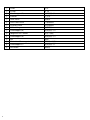
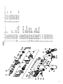
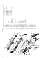
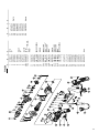
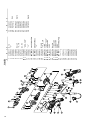
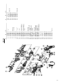
6. Service parts list
A: Item No.
B: Code No.
C: No. Used
D: Remarks
CAUTION
Repair, modification and inspection of Hitachi Power
Tools must be carried out by a Hitachi Authorized
Service Center.
This Parts List will be helpful if presented with the
tool to the Hitachi Authorized Service Center when
requesting repair or other maintenance.
In the operation and maintenance of power tools, the
safety regulations and standards prescribed in each
country must be observed.
MODIFICATION
Hitachi Power Tools are constantly being improved
and modified to incorporate the latest technological
advancements.
Accordingly, some parts (i.e. code numbers and/or
design) may be changed without prior notice.
NOTE:
Due to HITACHI’s continuing program of research and
development, the specifications herein are subject to
change without prior notice.

7
中國語
一般安全規則
警告!
請通讀本說明書
若不遵守下列注意事項,可能會導致電擊、火災及/或
嚴重傷害。
下述警告中的術語「電動工具」,指插電 (有線) 電
動工具或電池 (無線) 電動工具。
請妥善保管本說明書
1) 工作場所
a) 工作場所應打掃乾淨,並保持充分的亮度。
雜亂無章及光線昏暗容易導致事故。
b) 請勿在易爆炸的環境中操作電動工具,如存在
易燃液體、氣體或粉塵的環境中。
電動工具產生的火花可能會點燃煙塵。
c) 操作電動工具時,孩童與旁觀者勿靠近工作場
所。
工作時分神可能會造成工具失控。
2) 電氣安全
a) 電動工具插頭必須與插座相配。
不得以任何形式改裝插頭。
不得對接地的電動工具使用任何轉接插頭。
原裝插頭及相配插座將會減少電擊的危險。
b) 應避免身體與大地或接地表面,如管道、散熱
器、爐灶、冰箱等的接觸。
若身體接觸大地或接地表面,更會增加電擊的
危險。
c) 電動工具不可任其風吹雨打,或置於潮濕的環
境中。
水進入電動工具也會增加電擊的危險。
d) 要小心使用電線。不要用電線提拉電動工具,
或拉扯電線來拆除工具的插頭。
電線應遠離熱源、油液,並避免接觸到銳利邊
緣或轉動部分。
電線損壞或攪纏在一起會增加電擊的危險。
e) 在室外操作電動工具時,請使用專用延伸線。
使用專用延伸線可降低電擊的危險。
3) 人身安全
a) 保持高度警覺,充分掌握情況,以正常的判斷
力從事作業。
疲勞狀態或服藥、飲酒後,請勿使用電動工
具。
操作電動工具時,一時的疏忽都可能造成嚴重
的人身傷害。
b) 使用安全設備。始終配戴安全眼鏡。
在適用條件下,使用防塵面罩、防滑膠鞋、安
全帽或聽覺保護裝置等安全設備,都會減少人
身傷害。
c) 謹防誤開動。插接電源前,請先確認開關是否
已切斷。
搬移電動工具時指頭接觸開關,或接通開關狀
態下插上電源插座,都容易導致事故。
d) 開動前務必把調整用鍵和扳手類拆除下來。
扳手或鍵留在轉動部分上,可能會造成人身傷
害。
e) 要在力所能及的範圍內進行作業。作業時腳步
要站穩,身體姿勢要保持平衡。
這樣在意外情況下可以更好地控制工具。
f) 工作時衣服穿戴要合適。不要穿著過於寬鬆的
衣服或佩帶首飾。頭髮、衣角和手套等應遠離
轉動部分。
鬆散的衣角、首飾或長髮都可能會捲入轉動部
分。
g) 如果提供連接除塵和集塵的設備,請確認是否
已經連接好並且使用正常。
使用這些設備可降低粉塵引起的危險。
4) 電動工具的使用和維護
a) 不要使勁用力推壓。應正確使用電動工具。
正確使用才能讓工具按設計條件有效而安全地
工作。
b) 如果電動工具不能正常開關,切勿使用。
無法控制開關的電動工具非常危險,必須進行
修理。
c) 進行調整、更換附件或存放工具前,請拆除電
源插頭。
此類預防安全措施可減少誤開動工具的危險。
d) 閒置不用的工具,應存放在孩童夠不到的地
方;不熟悉電動工具或本說明書的人員,不允
許操作本工具。
未經培訓的人員使用電動工具非常危險。
e) 妥善維護工具。檢查轉動部分的對準、連接,
各零件有無異常,及其他足以給工作帶來不良
影響的情況。
如有損壞,必須修理後才能使用。
許多事故都是因工具維護不良引起的。

8
中國語
規 格
選購附件(分開銷售)
1. 用于六腳頭螺絲
六腳座
副制動器 (B)
標 準 附 件
(1) 2 號十字形鑽頭 ..... 1 (W6VM, W6V4, W6VA4)
(2) 磁性六腳座
(H = 10 mm) .............. 1 (W6VB3, W8VB2)
型 式 W6VM W6V4 W6VA4 W6VB3 W8VB2
電 壓(按地區)* (110V, 115V, 120V, 127V, 220V, 230V, 240V)
輸入功率 620 W
額定輸出功率 270 W
空載轉速 0 – 6000轉/分 0 – 4500轉/分 0 – 3000轉/分 0 – 2600轉/分 0 – 1700轉/分
螺絲旋緊能力 6 mm 8 mm
鑽頭杆的尺寸 6.35 mm 六角形
重 量(不含線纜) 1.4 kg 1.5 kg
*當須改變地區時應檢查產品上的銘牌。
標準附件可能不預先通告而徑予更改。
f) 保持工具鋒利、清潔。
正確維護工具,使其保持鋒利,作業順暢,便
於控制。
g) 請根據本說明書,按照特殊類型電動工具的方
式,使用本工具、附件及鑽頭,並考慮作業條
件及具體的作業情況。
電動工具用於規定外的作業,可能會導致危險
狀況。
磁性型
H = 6.35 mm
H = 7.94 mm
H = 9.53 mm
H = 10 mm
無磁性型
H = 6.35 mm
H = 7.94 mm
H = 9.53 mm
H = 10 mm
H 1/4
H 5/16
H 3/8
5) 維修
a) 本電動工具的維修必須由專業人員使用純正配
件進行。
這樣才能確保電動工具的安全性。
注意事項:
不可讓孩童和體弱人士靠近工作場所。
應將不使用的工具存放在孩童和體弱人士伸手不及的
地方。

9
中國語
(1)用于六腳頭螺絲︰
按圖 3 所示方法,將六腳頭螺絲裝配在六腳座上,
並將從副製動器末端至螺絲頭底部的距離設為
1 – 1.5 mm。
(2)使用清水牆螺絲時:
按圖 4 所示方法,將清水牆螺絲裝配在鑽頭上,並
將從副制動器末端至螺絲頭底部的距離設定為
1.5 – 2 mm。
(3)使用十字形頭自鑽螺絲時:
按圖 5 所示方法,將自鑽螺絲裝配在鑽頭上,並將
從副制動器末端至螺絲頭底部的距離設定為
1 – 1.5 mm。
6. 安裝鑽頭
詳細請參考“安裝與拆卸鑽頭”。
安裝與拆卸六腳座或鑽頭
1. 拆卸六腳座(圖 6)
(1)一邊旋轉副制動器一邊將其拔出。
(2)拆下六腳座后,用手或鉗子夾住鑽頭的反面,用另
一鉗子拉出鑽頭。
2. 拆卸鑽頭(圖 7)
與六腳座相似,拆下副制動器(G)並拆下鑽頭
座,然后用鉗子拉出鑽頭。
3. 拆卸鑽頭(圖 8)
與六腳座相似,拆下副制動器(F)並拆下鑽頭
座,然后用鉗子拉出鑽頭。
4. 安裝六腳座或鑽頭
請按與拆卸時的相反順序來安裝鑽頭。
3. 塑料套
選購附件可能不預先通告而徑予更改。
用 途
○ 旋緊六腳頭螺絲。
○ 清水牆螺絲、木螺絲和自鑽螺絲的旋緊。
作 業 之 前
1. 電源
確認所使用的電源與工具銘牌上標示的規格是否相
符。
2. 電源開關
確認電源開關已經切斷。若電源開關接通,則插頭
插入電源插座時電動工具將出其不意地立刻轉動,
從而招致嚴重事故。
3. 延伸線纜
若作業場所移到離開電源的地點,應使用容量足
夠、鎧裝合適的延伸線纜,並且要盡可能地短些。
4. 確認鑽頭的旋轉方向(圖 1)
將換向開關杆設為“R”側位置時,鑽頭按順時針
方向旋轉(從后面看時)。將換向開關杆設為
“L”側位置時,鑽頭按逆時針方向旋轉並可以旋
鬆螺絲。
5. 調節旋緊深度(圖 2)
左右旋轉定位器來調節上緊的深度,直至有卡嗒的
感覺。
2. 用于其他螺絲
磁性鑽頭座
(短型)
磁性鑽頭座
無磁性鑽頭座
副制動器鑽頭座
螺絲頭
1號
2號
3號
1號
2號
1號
2號
3號
1號
2號
B 尺寸
4 mm
5 mm
副制動器 (G)
副制動器 (F)

10
中國語
電動起子機的使用方法
1. 開關操作法和轉速的調節法
鑽頭的轉速的可變範圍為 0-6000 轉∕分
(W6VM),0 - 4500 轉∕分(W6V4),0 -
3000 轉∕分(W6VA4),0-2600 轉∕分
(W6VB3),0 - 1700 轉∕分(W8VB2)鑽
頭的轉速是由扳機開關的扣動程度而決定的。扳機
開關完全被拉起時,鑽頭便達到最大轉速 6000
轉∕分(W6VM),4500 轉∕分(W6V4),
3000 轉∕分(W6VA4),2600 轉∕分
(W6VB3),1700 轉∕分(W8VB2)。
若想連續進行操作,請扣動扳機開關后再按下開關
停止銷。這樣,即使鬆開手指,扳機開關也會停在
ON (開)的位置。再一次扣動扳機時,開關停止
銷便會自動鬆開。這時,鬆開手指的話,扳機開關
便回到 OFF(關)的位置。
2. 電動起子機的操作法
將開關設在 ON(開)的位置時,馬達開始轉動,
但六腳座(或鑽頭)仍靜止不動。請將六腳座插進
螺絲頭部的槽中,並將螺絲起子機壓在螺絲上。此
時,六腳座便開始轉動,並將螺絲旋緊。
注意:
操作時,螺絲起子機必須與螺絲頭保持完全垂
直。若不垂直的話,因驅動力沒被全部傳遞給螺
絲,螺絲頭和/或六腳座會受損。將螺絲起子機
從螺絲上鬆開時,六腳座便會自動停止轉動。
3. 六腳座的旋轉方向
將換向開關杆設于 R 側時,六腳座按順時針方向
旋轉(從后側看時)。而將換向開關杆設于 L 側
時,六腳座按逆時針方向旋轉,這時,便可旋鬆或
收回螺絲。
注意︰
在馬達旋轉時,切勿更改六腳座(或鑽頭座)的
旋轉方向。這樣做會嚴重損壞馬達。在更改六腳
座(或鑽頭座)的旋轉方向之前,請將電源開關
設于 OFF(關)處。
維 護 和 檢 查
1. 檢查六腳座(或鑽頭)
如繼續使用已破損了的六腳座(或鑽頭),會損傷
螺絲頭。因此,一旦注意到六腳座(或鑽頭)過度
破損,請立即用新六腳座(或鑽頭)更換之。
2. 檢查安裝螺釘
要經常檢查安裝螺釘是否緊固妥善。若發現螺釘鬆
了,應立即重新扭緊,否則會導致嚴重的事故。
3. 電動機的維護
電動機繞線是電動工具的心臟部。應仔細檢查有無
損傷,是否被油液或水沾濕。
4. 檢查碳刷
為了長期的安全及觸電保護,本工具上碳刷的檢查
與更換必須由日立授權的服務中心承擔。
5. 保養與修理
所有高質量的電動工具最終都需要對由於正常使用
而磨損的零件進行保養或更換。為了確保使用合格
的備件,所有保養及修理必須由日立授權的服務中
心承擔。
注意︰
○ 務必請遵循如上所述的組裝順序。如內部導
線碰到了轉子,或夾在了手柄罩與外殼之
間,會導致操作者嚴重觸電的危險。
○ 切勿亂碰拿那些與更換碳刷不相關的零件。
6. 維修部件目錄
A:項目號碼
B:代碼號碼
C:所使用號碼
D:備註
注意:
日立電動工具的修理、維護和檢查必須由日立所認
可的維修中心進行。
當尋求修理或其他維護時,將本部件目錄與工具一
起提交給日立所認可的維修中心會對您有所幫助。
在操作和維護電動工具中,必須遵守各國的安全規
則和標准規定。
改進:
日立電動工具隨時都在進行改進以適應最新的技術
進步。
因此,有些部件(如,代碼號碼和/或設計)可能
未預先通知而進行改進。
注︰為求改進,本手冊所載規格可能不預先通告而徑
予更改。

11
ABCD
1 876-031 1 S-16
2 323-487 1 “3”
3 323-488 1
4 971-468 1
5 317-662 1
6 321-057 3 D4×25
7 323-486 1 “5”
8 872-573 1
9 959-148 2 D3.175
10 1 323-491 1 “8, 9”
10 2 323-492 1 “8, 9” “HKG,
THA, TPE, KOR”
11 323-476 1
12 306-024 1
13 323-504 1
14 608-VVM 1 608VVMC2PS2L
15 933-545 2
16 301-936 2 M4×10
17 690-0VV 1 6900VVCMPS2L
18 323-503 1 “14-17”
19 1 360-676 1 110V-120V
19 2 360-677U 1 120V “14, 23”
19 3 360-677E 1 220V-230V
19 4 360-677F 1 240V
20 323-472 1
21 961-672 2 D4×50
22 1 340-599C 1 110V-120V
22 2 340-599E 1 220V-230V
22 3 340-599F 1 240V
23 608-VVM 1 608VVC2PS2L
24
————
1
25
————
1
26 323-471 1
27
————
1
28 323-512 2
29 999-091 2
30 323-489 1
31 323-480 1
32 323-479 1
33 323-490 1
34 323-481 1
35 323-483 1
ABCD
36 981-373 2
37 953-327 1 D8.8
38
————
1
39 937-631 1
40 984-750 2 D4×16
41 959-140 2
42 930-039 1
43 994-273 1
44 343-478 2
45 992-635 1
46 323-484 1
47 301-653 3 D4×20
W6VM

12
ABCD
1 876-031 1 S-16
2 323-487 1 “3”
3 323-488 1
4 971-468 1
5 317-662 1
6 321-057 3 D4×25
7 323-486 1 “5”
8 872-573 1
9 959-148 2
10 1 323-491 1 “8, 9”
10 2 323-482 1 “8, 9” “TPE,
THA, HKG, KOR”
11 323-476 1
12 306-024 1
13 323-485 1
14 608-VVM 2 608VVC2PS2L
15 933-545 1
16 301-936 2 M4×10
17 323-473 1
18 1 360-672 1 110V
18 2 360-673U 1 120V
18 3 360-673E 1 220V-230V
18 4 360-673F 1 240V
19 323-472 1
20 961-672 2 D4×50
21 1 340-599C 1 110V-120V
21 2 340-599E 1 220V-230V
21 3 340-599F 1 240V
22 608-VVM 1 608VVC2P2L
23
————
1
24
————
1
25 323-471 1
26
————
1
27 323-512 2
28 999-091 2
29 323-489 1
30 323-480 1
31 323-479 1
32 323-490 1
33 323-481 1
34 323-483 1
35 981-373 2
ABCD
36 953-327 1 D8.8
37
————
1
38 937-631 1
39 984-750 2 D4×16
40 959-140 2
41 930-039 1
42 994-273 1
43 323-478 2
44 992-635 1
45 323-484 1
46 301-653 3 D4×20
W6V4

13
ABCD
1 876-031 1 S-16
2 323-487 1 “3”
3 323-488 1
4 971-468 1
5 317-662 1
6 321-057 3 D4×25
7 323-486 1 “5”
8 872-573 1
9 959-148 2 D3.175
10 1 323-491 1 “8, 9”
10 2 323-482 1 “8, 9” “TPE, SIN,
HKG”
11 323-476 1
12 306-024 1
13 323-474 1
14 608-VVM 2 608VVC2PS2L
15 933-545 1
16 301-936 2 M4×10
17 323-473 1
18 1 360-670 1 100V-110V
18 2 360-671U 1 120V “14, 22”
18 3 360-671 1 220V-230V
18 4 360-671F 1 240V
19 323-472 1
20 961-672 2 D4×50
21 1 340-599C 1 110V-120V
21 2 340-599E 1 220V-230V
21 3 340-599F 1 240V
22 608-VVM 1 608VVC2PS2L
23
————
1
24
————
1
25 323-471 1
26
————
1
27 323-512 2
28 999-091 2
29 323-489 1
30 323-480 1
31 323-479 1
32 323-490 1
33 323-481 1
34 323-483 1
35 981-373 2
36 953-327 1 D8.8
ABCD
37
————
1
38 937-631 1
39 984-750 2 D4×16
40 959-140 2
41 930-039 1
42 994-273 1
43 323-478 2
44 992-635 1
45 323-484 1
46 301-653 3 D4×20
W6V
A4

14
ABCD
1 876-031 1 S-16
2 323-487 1 “3”
3 323-488 1
4 971-468 1
5 317-662 1
6 321-057 3 D4×25
7 323-498 1 “5, 16”
8 872-573 1
9 959-148 2 D3.175
10 1 317-664 1
10 2 323-507 1 “USA, CAN”
11 306-024 1
12 323-494 1 “13”
13 323-495 1
14 608-VVM 2 608VVMC2PS2L
15 933-545 1
16 608-VVM 1 608VVC2PS2L
17 323-496 1 “18”
18 307-337 1
19 323-497 1
20 301-936 2 M4×10
21 323-493 1 “14, 15, 20”
22 1 360-674 1 110V
22 2 360-675U 1 120V “14, 26“
22 3 360-675E 1 220V-230V
22 4 360-675F 1 240V
23 323-472 1
24 961-672 2 D4×50
25 1 340-599C 1 110V-120V
25 2 340-599U 1 220V-230V
25 3 340-599F 1 240V
26 608-VVM 1 608VVMC2PS2L
27
————
1
28
————
1
29 323-471 1
30
————
1
31 323-512 2
32 999-091 2
33 323-489 1
34 323-480 1
35 323-479 1
36 323-490 1
37 323-481 1
ABCD
38 323-483 1
39 981-373 2
40 953-327 1 D8.8
41
————
1
42 937-631 1
43 984-750 2 D4×16
44 959-140 2
45 930-039 1
46 994-273 1
47 323-478 2
48 992-635 1
49 323-484 1
50 301-653 3 D4×20
W6VB3

15
ABCD
1 876-031 1
2 323-487 1 “3”
3 323-488 1
4 971-468 1
5 317-662 1
6 321-057 3 D4×25
7 323-498 1 “5, 16”
8 872-573 1
9 959-148 2
10 317-664 1 “8, 9”
11 306-024 1
12 323-505 1 “13”
13 323-495 1
14 608-VVM 2 608VVC2PS2L
15 933-545 1
16 608-VVM 1 608VVC2PS2L
17 307-338 1 “18”
18 307-337 1
19 323-497 1
20 301-936 2 M4×10
21 323-473 1 “14, 15, 20”
22 1 360-674 1 110V
22 2 360-675E 1 220V-230V
22 3 360-675F 1 240V
23 323-472 1
24 961-672 2 D4×50
25 1 340-599C 1 110V-120V
25 2 340-599E 1 220V-230V
25 3 340-599F 1 240V
26 608-VVM 1 608VVC2PS2L
27
————
1
28
————
1
29 323-471 1
30
————
1
31 323-512 2
32 999-091 2
33 323-480 1
34 323-479 1
35 323-481 1
36 323-483 1
37 981-373 2
38 953-327 1 D8.8
ABCD
39
————
1
40 937-631 1
41 984-755 2 D4×16
42 959-140 2
43 930-039 1
44 994-273 1
45 323-478 2
46 992-635 1
47 323-484 1
48 301-653 3 D4×20
W8VB2

407
Code No. C99129931
Printed in Malaysia
Hitachi Koki Co., Ltd.
-
 1
1
-
 2
2
-
 3
3
-
 4
4
-
 5
5
-
 6
6
-
 7
7
-
 8
8
-
 9
9
-
 10
10
-
 11
11
-
 12
12
-
 13
13
-
 14
14
-
 15
15
-
 16
16
-
 17
17


Hitachi Power Screwdriver W 6V4 ユーザーマニュアル
- カテゴリー
- パワーツール
- タイプ
- ユーザーマニュアル
他の言語で
関連論文
-
Hitachi DH 40SC Handling Instructions Manual
-
-
Hikoki DV18DL2 ユーザーマニュアル
-
-
Hikoki CC14SF ユーザーマニュアル
-
Hitachi WH 18DBEL Handing Instructions
-
Hikoki C 12LSH ユーザーマニュアル
-
-
-
Hikoki DH24PB3 ユーザーマニュアル