
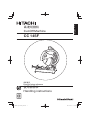
Cut-Off Machine
CC 14SF
English
Handling instructions
Keep for future reference

2

3

4
°
°

5

6

7
°
° °

8
○
○
○

9

10
33
45
B
B
501
2
1
3
4
5
6
7
8
20
6
11
12
13
14
13
16
87
19
21
5
46
47
48
49
27
28
26
29
30
31
32
90
34
35
36A
37
38
41
40
39
42
69
43
44
50
51
52
53
61
62
46
70
71
72
73
74
75
74
76
11
11
25
79
77
78
80
54
55
56
64
65
66
67
68
81
82
83
84
85
86

11

12

English
13
GENERAL OPERATIONAL PRECAUTIONS
WARNING!
When using electric tools, basic safety precautions should always be followed to reduce
the risk of fi re, electric shock and personal injury, including the following.
Read all these instructions before operating this product and save these instructions.
For safe operations:
1. Keep work area clean. Cluttered areas and benches invite injuries.
2. Consider work area environment. Do not expose power tools to rain. Do not use
power tools in damp or wet locations. Keep work area well lit.
Do not use power tools where there is risk to cause fire or explosion.
3. Guard against electric shock. Avoid body contact with earthed or grounded
surfaces. (e.g. pipes, radiators, ranges, refrigerators).
4. Keep children away. Do not let visitors touch the tool or extension cord. All visitors
should be kept away from work area.
5. Store idle tools. When not in use, tools should be stored in a dry, high or locked up
place, out of reach of children.
6. Do not force the tool. It will do the job better and safer at the rate for which it was
intended.
7. Use the right tool. Do not force small tools or attachments to do the job of a heavy
duty tool. Do not use tools for purposes not intended; for example, do not use
circular saw to cut tree limbs or logs.
8. Dress properly. Do not wear loose clothing or jewellery, they can be caught in
moving parts. Rubber gloves and non-skid footwear are recommended when
working outdoors. Wear protecting hair covering to contain long hair.
9. Use eye protection. Also use face or dust mask if the cutting operation is dusty.
10. Connect dust extraction equipment.
If devices are provided for the connection of dust extraction and collection
facilities ensure these are connected and properly used.
CONTENTS
GENERAL OPERATIONAL PRECAUTIONS ................................................13
PRECAUTIONS ON USING CUT-OFF MACHINE .......................................14
SYMBOL .......................................................................................................15
NAME OF PARTS.........................................................................................15
SPECIFICATIONS ........................................................................................ 15
STANDARD ACCESSORIES .......................................................................15
APPLICATION ..............................................................................................16
PRIOR TO OPERATION ...............................................................................16
CUTTING PROCEDURES ............................................................................ 17
MOUNTING AND DISMOUNTING THE CUT-OFF WHEEL .........................17
HOW TO OPERATE .....................................................................................18
MAINTENANCE AND INSPECTION ............................................................19
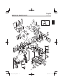
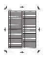
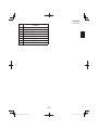
SERVICE PARTS LIST .................................................................................21

English
14
11. Do not abuse the cord. Never carry the tool by the cord or yank it to disconnect it
from the receptacle. Keep the cord away from heat, oil and sharp edges.
12. Secure work. Use clamps or a vise to hold the work. It is safer than using your hand
and it frees both hands to operate tool.
13. Do not overreach. Keep proper footing and balance at all times.
14. Maintain tools with care. Keep cutting tools sharp and clean for better and safer
performance. Follow instructions for lubrication and changing accessories. Inspect
tool cords periodically and if damaged, have it repaired by authorized service
center. Inspect extension cords periodically and replace, if damaged. Keep handles
dry, clean, and free from oil and grease.
15. Disconnect tools. When not in use, before servicing, and when changing
accessories such as blades, bits and cutters.
16. Remove adjusting keys and wrenches. Form the habit of checking to see that keys
and adjusting wrenches are removed from the tool before turning it on.
17. Avoid unintentional starting. Do not carry a plugged-in tool with a finger on the
switch. Ensure switch is off when plugging in.
18. Use outdoor extension leads. When tool is used outdoors, use only extension
cords intended for outdoor use.
19. Stay alert. Watch what you are doing. Use common sense. Do not operate tool
when you are tired.
20. Check damaged parts. Before further use of the tool, a guard or other part that is
damaged should be carefully checked to determine that it will operate properly and
perform its intended function. Check for alignment of moving parts, free running
of moving parts, breakage of parts, mounting and any other conditions that may
affect its operation. A guard or other part that is damaged should be properly
repaired or replaced by an authorized service center unless otherwise indicated
in this handling instructions. Have defective switches replaced by an authorized
service center. Do not use the tool if the switch does not turn it on and off.
21. Warning
The use of any accessory or attachment, other than those recommended in this
handling instructions, may present a risk of personal injury.
22. Have your tool repaired by a qualified person.
This electric tool is in accordance with the relevant safety requirements. Repairs
should only be carried out by qualified persons using original spare parts.
Otherwise this may result in considerable danger to the user.
PRECAUTIONS ON USING CUT-OFF MACHINE
1. Before using it, ascertain that the cut-off wheel is not cracked or split. Always
make a trial run before use to confirm that the Cut-Off Machine does not involve
abnormalities.
2. Use the normal cut-off wheel on its normal working surface.
3. Guard against cut-off sparks.
4. Properly replace the cut-off wheel.
5. Always pay attention that the cut-off wheel clamping parts are never impaired.
Defective parts will cause damage to the cut-off wheel.
6. Ensure that the workpiece is free of foreign matter such as nails.

English
15
SYMBOL
WARNING
The following show symbols used for the machine. Be sure that you understand their
meaning before use.
To reduce the risk of injury, user must read instruction manual.
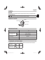
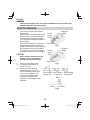
NAME OF PARTS
Wheel cover
Spark chute
Handle
Sub cover (A)
Fig. 1
SPECIFICATIONS
Voltage 220 V
Input 2000 W
Max. cutting dimensions
Height × width
90° 70 mm × 235 mm
45° 106 mm × 106 mm
No-Load Speed 3800 /min
Max. working peripheral speed 4800 m/min
Weight 17 kg
STANDARD ACCESSORIES
In addition to the main unit (1 unit), the package contains the accessories listed in the below.
Cut-off wheel 1
Hex. bar wrench
1

English
16
APPLICATION
Cutting of various metallic materials such as pipes, round bars and shaped steel and siding board.
PRIOR TO OPERATION
1. Power source
Ensure that the power source to be utilized conforms to the power requirements specifi ed
on the product nameplate.
2. Power switch
Ensure that the power switch is in the OFF position. If the plug is connected to a receptacle
while the power switch is in the ON position, the power tool will start operating immediately,
which could cause a serious accident.
3. Extension cord
When the work area is removed from the power source, use an extension cord of suffi cient
thickness and rated capacity. The extension cord should be kept as short as practicable.
4. Install the machine on a level fl at place, and keep it in a stable condition. Prior to shipping,
the equipment is subjected to a rigid factory inspection to prevent electric shocks during
operation.
5. Since movable portions are secured by tension of a chain while in transit, remove the chain
from the chain hook by slightly depressing the switch handle.
6. Ascertain that all cut-off wheels are in perfect condition, and do not display scars and
cracks.
7. Although they have been fully clamped at the factory prior to delivery, reclamp the clamping
nuts securely for safety.
8. Possible accidents such as a cracked cut-off wheel is prevented by this protective cover
(wheel cover). Although it has been fully clamped at the factory prior to delivery, securely
reclamp the mounting screws for safety.
9. When replacing the cut-off wheel, ensure that the replacement cutting wheel has a
designed circumferential speed in excess of 4800 m/min.
10. Ensure that the bar spanner used for tightening or removing the cut-off wheel is not
attached to the machine.
11. Ensure that the material is securely fastened with the vise. If it is not, a serious accident
could be caused if the material comes loose or the cut-off wheel breaks during operation.
12. Continued cutting without noticing a cracked or split cut-off wheel may prove to be very
hazardous. Before starting operation, make a trial run to confi rm that no abnormalities are
involved.
Trial run periods:
When replacing the cut-off wheel ........... Over 3 minutes.
When starting routine work ..................... Over 1 minute.
13. Rotate the cut-off wheel to inspect any facial defl ection. A heavy defl ection will cause the
cut-off wheel to shift.

English
17
CUTTING PROCEDURES
CAUTION
It is dangerous to remove or install the workpiece while the cut-off wheel turning.
1. Operating the switch
The switch is switched on by manually pulling the trigger and cut off by releasing the trigger
to the original location. The switch can operate continuously, even after releasing the
trigger, by pushing the stopper after pulling the trigger. The stopper can be removed by
pulling the trigger again and the switch is cut off with the release of the trigger.
2. Cutting
(1) Rotate the cut-off wheel, gently press down the handle, and bring the cut-off wheel close to
the cutting material.
(2) When the cut-off wheel contacts the cutting material, gently press down the handle further
and start cutting.
(3) When cutting (or designated slotting) is completed, raise the handle and restore it to its
original position.
(4) At the termination of each cutting process, turn OFF the switch to stop rotation and proceed
with the subsequent cutting job.
CAUTION
It does not necessarily cut rapidly when putting more force on the handle.
Too much force on the handle will put excessive pressure on the motor and reduce
its capacity.
Do not fail to switch OFF the switch after operation is completed and pull the plug
out.
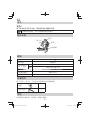
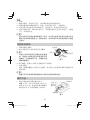
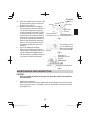
MOUNTING AND DISMOUNTING THE CUT-OFF WHEEL
1. Dismounting the cut-off wheel (Fig. 2)
(1) Press the stopper and loosen the bolt with a
hex. bar wrench.
CAUTION
When the mounting shaft for cut-off wheel
cannot be fi xed with pressing the stopper,
turn the bolt with a hex. bar wrench while
pressing the stopper. The mounting shaft
for cut-off wheel is fi xed when the stopper
has been lowered.
(2) Remove the bolt, washer (A), and the wheel washer and detach the cut-off wheel.
2. Mounting the cut-off wheel
Throughly remove dust from the wheel washers and bolt then mount the wheel by following
the dismounting procedures in reverse order.
Motor
Stopper
Hex. bar wrench
Cut-off wheel
Fig. 2

English
18
CAUTION
Confi rm that the stopper which was used for installation and removal of the cut-off
wheel has returned to the retract position.
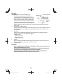
HOW TO OPERATE
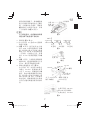
1. Procedure for fi xing the cutting material
(Fig. 3 and 4)
Place the workpiece material between vise
(A) and vise (B), raise the clutch and push
the screw handle to bring vise (A) lightly
into contact with the workpiece material, as
shown in Fig. 3.
Then, turn the clutch down, and securely
fi x the workpiece material in position by
turning the screw handle. When the cutting
job is completed, turn the screw handle 2
or 3 times to loosen the vise, and remove
the workpiece material, as shown in Fig. 4.
CAUTION
Never remove or install a workpiece
material while the cut-off wheel is
rotating, to avoid personal injury.
2. Cutting at angles (Fig. 5 and 6)
(1) The machine permits cutting at
angles of 45° or 60°.
(2) Loosen the two M10 hexagon
socket head bolts on the vise (B),
then set the working surface on the
vise-jaw at any angles of 0°, 30°,
or 45° as shown in Fig. 6. Upon
completion of setting, securely
tighten the two M10 hexagon socket
head bolts.
Vise (B)
Vise (A)
Clutch
Screw handle
Workpiece
material
Fig. 3
Fig. 4
Vise (B)
Vise (A)
Clutch
Screw handle
Workpiece
material
90°
45°
60°
Fig. 5
When setting at
an angle of 0°
When setting at
an angle of 30°
When setting at
an angle of 45°
Vise (B)
10 mm bolts
Fig. 6

English
19
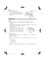
(3) When wide material is cut with angle, it will
be fi rmly camped by fi xing a steel board
like Fig. 7 to the vise (B).
3. Moving the stationary vise-jaw (Fig. 8)
The vise opening is set at the maximum of
170 mm when shipped from the factory.
In case an opening of more than 170 mm
is required, move the vise to the position
shown by the chain line after unscrewing
the two bolts. The maximum opening can
be set in two steps 205 mm and 240 mm.
When the cutting material is excessively
wide, the vise can be eff ectively used by
repositioning the stationary side of the
vise-jaws.
4. How to use metallic block (Fig. 9)
When the cut-off wheel has a reduced
outer diameter, insert between the vise (A)
and (B) a metallic block slightly smaller
than the dimension of workpiece being cut
to use the cut-off wheel economically.
MAINTENANCE AND INSPECTION
CAUTION
Be sure to switch off and pull off the plug from the power outlet before inspection
and maintenance.
1. Replacing a cut-off wheel
When the cut-off wheel has already become dull while continually using, the unnecessary
load is got from the motor. Consequently, redress or replace a dull cut-off wheel to ensure
grinding effi ciency.
120 mm
60 mm
27 mm
28 mm
45 mm
2 - 6.5 mm
6 mm nuts
Vise (B)
Steel board (More
than thickness 6 mm)
Flat hd. screw of
more than 6 mm × 15
Fig. 7
Vise (B)
The vise-jaws open to
170 mm while the vise
can be set in two steps
205 mm and 240 mm.
Fig. 8
Dimension of
workpiece to be cut
Vise (B)
Metallic block
Vise (A)
Dimension of Metallic block
Fig. 9

English
20
2. Inspecting the carbon brushes (Fig. 10)
The Motor employs carbon brushes which are
consumable parts. When they become worn to or
near the “wear limit”, it could result in motor trouble.
When an auto-stop carbon brush is equipped, the
motor will stop automatically. At that time, replace
both carbon brushes with new ones which have the
same carbon brush Number shown in the fi gure. In
addition, always keep carbon brushes clean and ensure that they slide freely within the
brush holders.
3. Inspecting the mounting screws
Regularly inspect all mounting screws and ensure that they are properly tightened. Should
any of the screws be loose, retighten them immediately. Failure to do so could result in
serious hazard.
4. Lubrication
Supply oil in the following oil supply points once a month so as to keep the machine
workable for a long time. (See Fig. 1 on page 15)
Oil supply points
○
Rotary part of shaft
○
Rotary part of vise
○
Slide way of vise (A)
5. Cleaning
Wipe off chip and waste adhered to the machine with a cloth or the like time to time. Be
careful not to make the motor portion wet with oil or water.
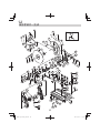
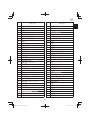
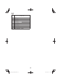
6. Service parts list
CAUTION
Repair, modifi cation and inspection of Hitachi Power Tools must be carried out by
a Hitachi Authorized Service Center.
This Parts List will be helpful if presented with the tool to the Hitachi Authorized
Service Center when requesting repair or other maintenance.
In the operation and maintenance of power tools, the safety regulations and
standards prescribed in each country must be observed.
6 mm
16 mm
[
44
]
Carbon Brush
Wear limit
No. of carbon brush
Fig. 10
ページが読み込まれています...
ページが読み込まれています...
ページが読み込まれています...
ページが読み込まれています...
-
 1
1
-
 2
2
-
 3
3
-
 4
4
-
 5
5
-
 6
6
-
 7
7
-
 8
8
-
 9
9
-
 10
10
-
 11
11
-
 12
12
-
 13
13
-
 14
14
-
 15
15
-
 16
16
-
 17
17
-
 18
18
-
 19
19
-
 20
20
-
 21
21
-
 22
22
-
 23
23
-
 24
24


他の言語で
- English: Hikoki CC14SF User manual
その他のドキュメント
-
Mitsubishi Electric GT2104-PMBD 取扱説明書
-
-
Munters Communicator V3.07 R1.0 CN 取扱説明書
-
Micro Motion LNG 系列科里奥利质量 流量计和密度仪表 取扱説明書
-
Furuno MU231 ユーザーマニュアル
-
Infocus W 6VM ユーザーマニュアル
-
Makita UA002G ユーザーマニュアル
-
Roland TD-50K 取扱説明書
-
-
Sony FE40L VPL-FX40 ユーザーマニュアル