Hitachi H 60MC Handling Instructions Manual
- カテゴリー
- パワーツール
- タイプ
- Handling Instructions Manual

Demolition Hammer
파괴햄머
H 60MC
Handling instructions
취급 설명서
Read through carefully and understand these instructions before use.
본 설명서를 자세히 읽고 내용을 숙지한 뒤 제품을 사용하십시오.

2
1
3
2
3
4
5
6
12
34
56
78

3
17 mm
a
8
9
7
910
11
9
a
0
74 7 mm
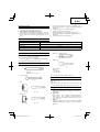
English
한국어
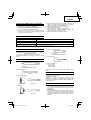
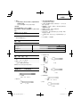
1
Tool shank
툴 섕크
2
Front cap
프런트 캡
3
Grip (A)
그립 (A)
4
Grip (B)
그립 (B)
5
Side handle
사이드 핸들
6
Grip
그립
7
Crank cover
크랭크 커버
8
Wear limit
마모 한도
9
No. of carbon brush
카본 브러시 번호
0
Auto-stop carbon brush
자동 정지 카본 브러시

4
English
GENERAL SAFETY RULES
WARNING!
Read all instructions
Failure to follow all instructions listed below may result in
electric shock, fi re and/or serious injury.
The term “power tool” in all of the warnings listed below
refers to your mains operated (corded) power tool or
battery operated (cordless) power tool.
SAVE THESE INSTRUCTIONS
1) Work area
a) Keep work area clean and well lit.
Cluttered and dark areas invite accidents.
b) Do not operate power tools in explosive
atmospheres, such as in the presence of
fl ammable liquids, gases or dust.
Power tools create sparks which may ignite the
dust of fumes.
c) Keep children and bystanders away while
operating a power tool.
Distractions can cause you to lose control.
2)
Electrical safety
a) Power tool plugs must match the outlet.
Never modify the plug in any way.
Do not use any adapter plugs with earthed
(grounded) power tools.
Unmodifi ed plugs and matching outlets will reduce
risk of electric shock.
b) Avoid body contact with earthed or grounded
surfaces such as pipes, radiators, ranges and
refrigerators.
There is an increased risk of electric shock if your
body is earthed or grounded.
c) Do not expose power
tools to rain or wet
conditions.
Water entering a power tool will increase the risk of
electric shock.
d) Do not abuse the cord. Never use the cord for
carrying, pulling or unplugging the power tool.
Keep cord away from heat, oil, sharp edges or
moving parts.
Damaged or entangled cords increase the risk of
electric shock.
e) When operating a power tool outdoors, use an
extension cord suitable for outdoor
use.
Use of a cord suitable for outdoor use reduces the
risk of electric shock.
3) Personal safety
a) Stay alert, watch what you are doing and use
common sense when operating a power tool.
Do not use a power tool while you are tired
or under the infl uence of drugs, alcohol or
medication.
A moment of inattention while operating power
tools may result in serious personal injury.
b) Use safety equipment. Always wear eye
protection.
Safety equipment such as dust mask, non-skid
safety shoes, hard hat, or hearing protection used
for appropriate conditions will reduce personal
injuries.
c) Avoid accidental starting. Ensure the switch is
in the off position before plugging in.
Carrying power tools with your fi nger on the switch
or plugging in power tools that have the switch on
invites accidents.
d) Remove any adjusting key or wrench before
turning the power tool on.
A wrench or a key left attached to a rotating part of
the power tool may result in personal injury.
e) Do not overreach. Keep proper footing and
balance at all times.
This enables better control of the power tool in
unexpected situations.
f) Dress properly. Do not wear
loose clothing or
jewellery. Keep your hair, clothing and gloves
away from moving parts.
Loose clothes, jewellery or long hair can be caught
in moving parts.
g) If devices are provided for the connection of
dust extraction and collection facilities, ensure
these are connected and properly used.
Use of these devices can reduce dust related
hazards.
4) Power tool use and care
a) Do not force the power tool. Use the
correct
power tool for your application.
The correct power tool will do the job better and
safer at the rate for which it was designed.
b) Do not use the power tool if the switch does
not turn it on and off .
Any power tool that cannot be controlled with the
switch is dangerous and must be repaired.
c) Disconnect the plug from the power source
before making any adjustments, changing
accessories, or storing power tools.
Such preventive safety measures reduce the risk of
starting the power tool accidentally.
d) Store idle power tools out
of the reach of
children and do not allow persons unfamiliar
with the power tool or these instructions to
operate the power tool.
Power tools are dangerous in the hands of
untrained users.
e) Maintain power tools. Check for misalignment
or binding of moving parts, breakage of parts
and any other condition that may aff ect the
power tools’
operation.
If damaged, have the power tool repaired
before use.
Many accidents are caused by poorly maintained
power tools.
f) Keep cutting tools sharp and clean.
Properly maintained cutting tools with sharp cutting
edges are less likely to bind and are easier to
control.
g) Use the power tool, accessories and tool bits
etc., in accordance with these instructions and
in the manner intended for the particular type
of power tool, taking into account the working
conditions
and the work to be performed.
Use of the power tool for operations diff erent from
intended could result in a hazardous situation.
5) Service
a) Have your power tool serviced by a qualifi ed
repair person using only identical replacement
parts.
This will ensure that the safety of the power tool is
maintained.
PRECAUTION
Keep children and infi rm persons away.
When not in use, tools should be stored out of reach
of children and infi
rm persons.

5
English
DEMOLITION HAMMER SAFETY WARNINGS
1. Wear ear protectors
Exposure to noise can cause hearing loss.
2. Use auxiliary handles supplied with the tool.
Loss of control can cause personal injury.
3. Do not touch the bit during or immediately after
operation. The bit becomes very hot during operation
and could cause serious burns.
SPECIFICATIONS
Voltage (by areas)*
(110 V, 120 V, 127 V, 220 V, 230 V, 240 V)
Power Input* 1250 W
Full-load Impact Rate 1600/min
Weight (without cord, side handle) 10.2 kg
* Be sure to check the nameplate on product as it is subject to change by areas.
STANDARD ACCESSORIES
(1) Case ..........................................................................1
(2) Side Handle
l type: bar type handle ........................1
ll type: D type handle ..........................1
Either type l or type ll Side handle is attached.
Standard accessories are subject to change without
notice.
OPTIONAL ACCESSORIES (sold separately)
○ Demolishing
(1) Bull Point
Overall Length: 280, 400 mm
○ Asphalt Cutting
(1) Cutter
○ Surface Roughing
+
(1) Bushing Tool (2) Shank
○ Tamp ing
+
(1) Rammer (2) Shank
○ Groove digging and edging
(1) Cold chisel
Overall Length: 280, 400 mm
○ Scooping Work
(1) Scoop
○ Hammer Grease A
500 g (in a can)
70 g (in a tube)
30 g (in a tube)
Optional accessories are subject to change without
notice.
APPLICATIONS
Demolishing concrete, chipping off concrete, grooving,
bar cutting, and driving piles.
Application examples:
Installation of piping and wiring, sanitary facility
installation, machinery installation, water supply and
drainage work, interior jobs, harbor facilities and other civil
engineering work.
PRIOR TO OPERATION
1. Power source
Ensure that the power source to be utilized conforms
to the power requirements specifi ed on the product
nameplate.
2. Power switch
Ensure that the power switch is in the OFF position. If
the plug is connected to a receptacle while the power
switch is in the ON
position, the power tool will start
operating immediately, which could cause a serious
accident.
4. Before starting to break, chip or drill into a wall, fl oor or
ceiling, thoroughly confi rm that such items as electric
cables or conduits are not buried inside.
5. Wear a mask when turning your head upward.
6. Properly set the bit holder.
7. At the start of work, confi rm screw tightening.
8. When working at a highly elevated location, pay
attention to articles and persons below.
9. Wear protective shoes to protect your feet.

6
English
3. Extension cord
When the work area is removed from the power source,
use an extension cord of suffi cient thickness and rated
capacity. The extension cord should be kept as short
as practicable.
4. Installing tools
CAUTION
Be sure to switch power OFF and disconnect the plug
from the receptacle to
avoid serious trouble.
NOTE
When using tools such as bull points, cutters, etc.,
make sure to use the genuine parts designated by our
company.
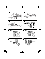
(1) Clean the shank portion of the tool.
(2) As shown in Fig. 1, pull grip (A) in the direction of
,
and insert the tool into a hole of the front cap.
(3) Adjust the groove position while turning the tool, and
furthermore insert it until it hits the end of the hole.
(4) Return grip (A) to its original position, pull the tool and
make sure it is locked completely (
Fig. 2).
5. Deciding Working Position of Tool
The tool can be turned every 30 degrees and can be
fi xed at the position of 12 steps.
(1) As shown in Fig. 3, if the grip (A) is turned in the
direction of
in a state where the grip (B) is pushed
in the direction of
,
the blade angle can be changed
freely to any desired position.
(2) Release grip (B) and turn the tool, and make sure that
it is locked completely.
6. Removing Tool
As shown in Fig. 1, pull grip (A), and pull out the tool.
CAUTION
Be sure to grip the handle and
side handle during
work. Do not hold by the grip (A) during work. If you
pull it by mistake, the bull point could jump out.
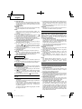
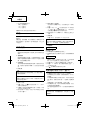
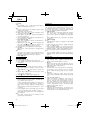
7. Move the side handle
For bar type handle
Fixing the side handle (Fig. 4).
(1) Rotate the side handle in a clockwise direction to
secure it.
(2) Set the side handle to a position that is suited to the
operation and then securely tighten the side handle.
For D type handle
The side handle can be fi xed at any desired position;
360 degrees, and can also be fi xed at any position in
the back-and-forth direction.
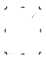
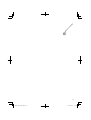
(1) Loosen the handle by turning the grip in the direction
of
as shown in Fig. 5.
(2) Adjust it to a position where vertical (up-and-down)
operation can be facilitated as illustrated in Fig. 6, Fig.
7, and Fig. 8.
(3) Turn the grip in the direction of
and fi x the handle.
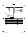
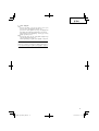
HOW TO USE THE DEMOLITION HAMMER
(Fig. 9)
1. After placing the tip of the tool on concrete surface,
switch ON.
The switch can be turned ON if the trigger is pulled and
OFF when it is released.
If the stopper is pressed while the trigger for the
switch is pulled, even if your fi nger is released from
the
trigger, the switch remains ON - convenient for
continuous operation.
To turn the switch OFF, pull the trigger again, and then
the stopper comes off .
2. By utilizing the empty weight of the machine and by
fi rmly holding the demolition hammer with both hands,
one can eff ectively control the subsequent recoil
motion.
Proceed at a moderate work-rate, the use of too much
force will impair effi ciency.
CAUTION
After long time of use, the
cylinder case becomes hot.
Therefore, be careful not to burn your hands.
GREASE REPLACEMENT
This machine is of full air-tight construction to protect
against dust and to prevent lubricant leakage. This
machine can be used without grease supplement for an
extended period of time. However, perform the grease
replacement to maintain the service life. Replace the
grease as described below.
1. Grease replacement period
You
should look at the grease when you change the
carbon brush. (See the section MAINTENANCE AND
INSPECTION.) Ask for grease replacement at the
nearest authorized Hitachi Service Center.
In the case that you are forced to change the grease by
yourself, please follow the following points.
2. How to replace grease
CAUTION
Before replacing the grease, turn the power off and pull
out the plug from the receptacle.
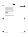
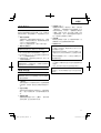
(1) Remove the crank cover and wipe off the old grease
inside. (Fig. 10)
(2) Supply 76 g (the standard volume to cover the
connecting rod) of Hitachi Electric Hammer Grease A
to
the crank case.
(3) After replacing the grease, install the crank cover
securely. At this time, do not damage or lose the oil
seal.
NOTE
The Hitachi Electric Hammer Grease A is of the
low viscosity type. When the grease is consumed,
purchase from an authorized Hitachi Service
Center.
MAINTENANCE AND INSPECTION
CAUTION
Be sure to switch power OFF and disconnect the plug
from the receptacle to avoid serious trouble.
1. Inspecting the tool
Since use of a dull tool will degrade effi ciency and
cause possible motor malfunction, sharpen or replace
the tool as soon as abrasion is noted.
2. Inspecting the
mounting screws
Regularly inspect all mounting screws and ensure that
they are properly tightened. Should any of the screws
be loose, retighten them immediately. Failure to do so
could result in serious hazard.
3. Maintenance of the motor
The motor unit winding is the very “heart” of the power
tool. Exercise
due care to ensure the winding does not
become damaged and/or wet with oil or water.
4. Inspecting the carbon brushes (Fig. 11)
The Motor employs carbon brushes which are
consumable parts. When they become worn to or near
the “wear limit”, it could result in motor trouble. When
an auto-stop
carbon brush is equipped, the motor will
stop automatically. At that time, replace both carbon
brushes with new ones which have the same carbon
brush Numbers shown in the fi gure. In addition, always
keep carbon brushes clean and ensure that they slide
freely within the brush holders.

7
English
5. Replacing carbon brushes
Loosen the set screw and remove the tail cover.
Remove the brush caps and carbon brushes. After
replacing the carbon brushes, do not forget to tighten
the brush caps securely and to install the tail cover.
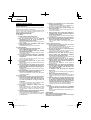
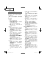
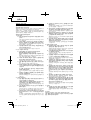
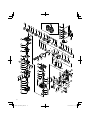
6. Service parts list
CAUTION
Repair, modifi cation and inspection of
Hitachi Power
Tool s must be carried out by a Hitachi Authorized
Service Center.
This Parts List will be helpful if presented with the
tool to the Hitachi Authorized Service Center when
requesting repair or other maintenance.
In the operation and maintenance of power tools, the
safety regulations and standards prescribed in
each
country must be observed.
MODIFICATIONS
Hitachi Power Tool s are constantly being improved
and modifi ed to incorporate the latest technological
advancements.
Accordingly, some parts may be changed without prior
notice.
NOTE
Due to HITACHI’s continuing program of research and
development, the specifi cations herein are subject to
change without prior notice.

8

9

10

11

12
한국어
일반적인 안전 수칙
경고!
설명서를 자세히 읽으십시오.
설명서의 내용에 따르지 않을 시에는 감전 사고나 화재가 발
생할 수 있으며 심각한 부상을 입을 수도 있습니다.
아래에 나오는 ‘전동 툴’이란 용어는 플러그를 콘센트에 연
결해 유선 상태로 사용하는 제품 또는 배터리를 넣어 무선
상태로 사용하는 제품을 가리킵니다.
설명서의 내용을 숙지하십시오.
1) 작업 공간
a) 작업 공간을 깨끗하게 청소하고 조명을 밝게 유지하
십시오.
작업 공간이 정리되어 있지 않거나 어두우면 사고가
날 수 있습니다.
b) 인화성 액체나 기체 또는 먼지 등으로 인해 폭발 위
험이 있는 환경에서는 전동 툴을 사용하지 마십시오.
전동 툴을 사용하다 보면 불꽃이 튀어서 먼지나 기체
에 불이 붙을 수 있습니다.
c) 어린이를 비롯하여 사용자 외에는 작업장소에 접근
하지 못하도록 하십시오.
주의가 산만해지면 문제가 생길 수 있습니다.
2) 전기 사용시 주의사항
a) 전동 툴 플러그와 콘센트가 일치해야 합니다.
플러그를 절대로 변형하지 마십시오.
접지된 전동 툴에는 어댑터 플러그를 사용하지 마십
시오.
플러그를 변형하지 않고 알맞은 콘센트에 꽂아 사용
하면, 감전 위험을 줄일 수 있습니다.
b) 파이프, 라디에이터, 레인지, 냉장고 등 접지된 표면
에 몸이 닿지 않도록 주의하십시오.
작업자의 몸이 접지되면, 감전될 위험이 있습니다.
c) 전동 툴에 비를 맞히거나 젖은 상태로 두지 마십시
오.
물이 들어가면 감전될 위험이 있습니다.
d) 코드를 조심해서 다루십시오. 전동 툴을 들거나 당기
거나 콘센트에서 뽑으려고 할 때 코드를 잡아당기면
안 됩니다.
열, 기름, 날카로운 물건, 움직이는 부품 등으로부터
코드를 보호하십시오.
코드가 파손되거나 엉키면 감전될 위험이 높아집니
다.
e) 실외에서 전동 툴을 사용할 때는 실외 용도에 적합한
연장선을 사용하십시오.
실외 용도에 적합한 코드를 사용해야 감전 위험이 줄
어듭니다.
3) 사용자 주의사항
a) 전동 툴을 사용할 때는 작업에 정신을 집중하고, 상
식의 범위 내에서 사용하십시오.
약물을 복용하거나 알코올을 섭취한 상태 또는 피곤
한 상태에서는 전동 툴을 사용하지 마십시오.
전동 툴을 사용할 때 주의가 흐트러지면 심각한 부상
을 입을 수 있습니다.
b) 안전 장비를 사용하십시오. 항상 눈 보호 장구를 착
용해야 합니다.
먼지 보호 마스크, 미끄럼 방지 신발, 안전모, 청각 보
호 장비 등을 사용하면 부상을 줄일 수 있습니다.
c) 전동 툴이 갑자기 작동되지 않도록 합니다. 플러그를
꽂기 전에 스위치가 ‘OFF’ 위치에 있는지 확인하
십시오.
손가락을 스위치에 접촉한 채 전동 툴을 들거나 스위
치가 켜진 상태로 플러그를 꽂으면 사고가 날 수 있습
니다.
d) 전원을 켜기 전에 조정 키 또는 렌치를 반드시 제거
해야 합니다.
전동 툴의 회전 부위에 키 또는 렌치가 부착되어 있으
면, 부상을 입을 수 있습니다.
e) 작업 대상과의 거리를 잘 조절하 십시오. 알맞은 발판
을 사용하고 항상 균형을 잡고 있어야 합니다.
그렇게 하면 예기치 못한 상황에서도 전동 툴을 잘 다
룰 수 있습니다.
f) 알맞은 복장을 갖추십시오. 헐렁한 옷이나 장신구를
착용하면 안 됩니다. 머리카락, 옷, 장갑 등을 움직이
는 부품으로부터 보호하십시오.
헐렁한 옷이나 장신구, 긴 머리카락이 부품에 딸려 들
어갈 수도 있습니다.
g) 분진 추출 및 집진 장비에 연결할 수 있는 장치가 제
공되는 경우, 그러한 장치가 잘 연결되어 있고 제대로
작동하는지 확인하십시오.
이러한 장치를 사용하면, 먼지와 관련된 사고를 줄일
수 있습니다.
4) 전동 툴 사용 및 관리
a) 전동 툴을 아무 곳에나 사용하지 마십시오. 용도에
알맞은 전동 툴을 사용하십시오.
적절한 전동 툴을 사용하면, 정상 속도로 안전하고 효
과적으로 작업을 수행할 수 있습니다.
b) 스위치를 눌렀을 때 전동 툴이 켜지거나 꺼지지 않으
면 사용하지 마십시오.
스위치로 작동시킬 수 없는 전동 툴은 위험하므로, 수
리를 받아야 합니다.
c) 전동 툴을 조정하거나 부속품을 바꾸거나 보관할 때
는 반드시 전원에서 플러그를 빼야 합니다.
이러한 안전 조치를 취해야 전동 툴이 갑자기 켜지는
위험을 피할 수 있습니다.
d) 사용하지 않는 전동 툴은 어린이의 손이 닿지 않는
곳에 보관하고, 사용법을 잘 모르는 사람이 사용하지
못하도록 하십시오.
전동 툴은 미숙련자가 다루기에는 매우 위험한 물건
입니다.
e) 전동 툴을 잘 관리하십시오. 움직이는 부품이 잘못
결합되어 있거나 꽉 끼어 움직이지 못하게 되어 있지
않은지 점검하십시오. 또한 전동 툴의 작동에 영향을
미칠 수 있는 기타 파손이 없는지 확인하십시오.
파손된 부분이 있는 경우, 사용하기 전에 수리하십시
오.
전동 툴을 제대로 관리하지 못해서 생기는 사고가 많
습니다.
f) 절삭 툴은 날카롭고 청결한 상태로 관리하십시오.
절삭 날을 날카로운 상태로 잘 관리하면, 원활하게
잘 움직이며 다루기도 훨씬 편합니다.
g) 설명서를 참조하여 전동 툴과 부속품, 툴 비트 등을
사용하십시오. 또한 작업 환경과 수행할 작업의 성격
을 고려해서 알맞은 종류의 전동 툴을 선택하고, 적
절한 방식으로 사용하십시오.
원래 목적과 다른 용도로 전동 툴을 사용하면 위험한
사고가 날 수 있습니다.
5) 서비스
a) 자격을 갖춘 전문가에게 서비스를 받고, 항상 원래
부품과 동일한 것으로 교체해야 합니다.
그렇게 하면 전동 툴을 보다 안전하게 사용할 수 있습
니다.
주의사항
어린이나 노약자가 가까이 오지 못하도록 하십시오.
전동 툴을 사용하지 않을 때는 어린이나 노약자의 손이 닿지
않는 곳에 보관해야 합니다.

13
한국어
철거 해머 안전 경고
1. 귀 보호 장구를 착용하십시오.
소음으로 인해 청력을 잃을 수 있습니다.
2. 함께 제공되는 보조 핸들을 사용하십시오.
장비를 제대로 다루지 못하면 부상을 입을 수 있습니다.
3. 작동 중 혹은 작동 직후에 비트를 만지지 마십시오. 작동
중에는 비트가 몹시 뜨거워지므로 화상을 입을 수 있습
니다.
사양
전압(지역별로 차이가 있음)*
(110V, 120V, 127V, 220V, 230V, 240V)
소비 전력* 1250W
분당 타격수 1600/분
중량(코드, 사이드 핸들 제외) 10.2kg
*지역별로 차이가 있을 수 있으므로, 제품 명판의 기재내용을 반드시 확인하십시오.
기본 부속품
(1) 케이스 .......................................................1
(2) 사이드 핸들
타입 I: 바 타입 핸들 .....................1
타입 II: D자형 핸들 .....................1
타입 I 또는 타입 II 사이드 핸들이 장착되어 있습니다.
기본 부속품은 예고 없이 변경될 수 있습니다.
옵션 부속품(별도 판매)
○ 철거하기
(1) 불 포인트
전체 길이: 280, 400mm
○ 아스팔트 절삭
(1) 커터
○ 황삭
+
(1) 부싱 툴 (2) 섕크
○ 평탄 작업
+
(1) 다짐판 (2) 섕크
○ 홈파기 및 가장자리 다듬기
(1) 콜드 치즐
전체 길이: 280, 400mm
○ 퍼내기 작업
(1) 삽
○ 햄머 윤활제 A
500g (캔)
70g (튜브형)
30g (튜브형)
옵션 부속품은 예고 없이 변경될 수 있습니다.
용도
콘크리트 파쇄 및 분쇄, 홈 파기, 봉 절삭, 항타(콘크리트 말
뚝을 박는 것) 등.
활용 예:
배관 설치 및 배선, 위생 시설 설치, 기계류 설치, 상하수도
관 작업, 인테리어 작업, 항만 시설 및 토목 관련 작업 등.
사용 전 주의사항
1. 전원
사용 전원이 제품 명판에 표시된 전원 요건과 부합하는지
확인하십시오.
2. 전원 스위치
전원 스위치가 ‘OFF’ 위치에 있는지 확인하십시오.
전원 스위치가 ‘ON’ 위치에 있는 상태로 플러그를 꽂
으면, 제품이 갑자기 작동하기 시작해서 심각한 사고가
날 수 있습니다.
3. 연장선
작업 공간에 전원이 없으면, 두께가 충분한 정격 용량의
연장선을 사용하십시오. 연장선은 가능한 한 짧을수록
좋습니다.
4. 벽, 바닥, 천장 등을 부수거나 깎거나 구멍을 뚫기 전에,
전기선이나 배관 같은 것이 묻혀 있지 않은지 철저히 확
인하십시오.
5. 고개를 위로 들 때 마스크를 착용하십시오.
6. 비트 홀더를 적합하게 설치하십시오.
7. 작업을 시작할 때 나사 조임 상태를 확인하십시오.
8. 높은 곳에서 작업할 때 아래에 있는 물품과 작업자에 주
의하십시오.
9. 보호 장화를 신어 발을 보호하십시오.

14
한국어
4. 툴 조립
주의
전원 스위치를 ‘OFF’ 상태에 두고 플러그를 뽑은 뒤
조립해야 사고를 예방할 수 있습니다.
참고
불포인트, 커터와 같은 공구를 사용할 때 당사가 지정한
순정품만 사용하십시오.
(1) 공구의 자루 부분을 닦으십시오.
(2) 그림 1과 같이 그립 (A)를
방향으로 잡아당겨 공구를
프런트 캡의 구멍에 넣으십시오.
(3) 공구를 돌리는 동안 홈 위치를 조정해 구멍 끝에 닿을 때
까지 계속 삽입하십시오.
(4) 그립 (A)를 원래의 위치로 되돌린 후 공구를 잡아당겨 완
전히 고정시키십시오 (그림 2).
5. 공구의 작업 위치 결정
공구는 30도 단위로 돌릴 수 있으며 12단계의 위치에 고
정시킬 수 있습니다.
(1) 그림 3과 같이, 그립 (B)를
방향으로 밀어놓은 상태
에서 그립 (A)를
방향으로 돌릴 경우, 블레이드 각도
를 원하는 위치로 자유롭게 변경할 수 있습니다.
(2) 그립 (B)를 놓고 공구를 돌려 완전히 고정시키십시오.
6. 공구 제거
그림 1과 같이, 그립 (A)를 잡아당기고 공구를 잡아당겨
빼십시오.
주의
작업 중에는 반드시 핸들과 사이드 핸들을 잡으십시오.
작업 중에 그립 (A)를 잡아 고정하지 마십시오. 실수로
잡아당길 경우 불포인트가 튀어나올 수 있습니다.
7. 사이드 핸들 이동
바 타입 핸들의 경우
사이드 핸들 고정(그림 4).
(1) 사이드 핸들을 시계 방향으로 돌려 고정하십시오.
(2) 사이드 핸들을 조작에 적합한 위치로 설정한 후 단단히
고정하십시오.
D자형 핸들의 경우
사이드 핸들을 원하는 위치에 즉 360도로 고정시킬 수
있으며, 전후 방향의 어느 위치에도 고정시킬 수 있습니
다.
(1) 그립을 그림 5와 같이
방향으로 돌려 느슨하게 하십
시오.
(2) 그림 6, 그림 7, 그림 8과 같이 쉽게 수직(상하) 조작할
수 있는 위치로 조정하십시오.
(3) 그립을
방향으로 돌려 핸들을 고정하십시오.
파괴햄머 사용법(그림 9)
1. 콘크리트 표면에 툴 끝을 갖다댄 후, 스위치를 켭니다.
트리거를 잡아당기면 스위치가 켜질 수 있고 트리거를 놓
으면 스위치가 꺼질 수 있습니다.
스위치용 트리거를 잡아당긴 상태에서 스토퍼를 누른 경
우, 심지어 트리거에서 손가락을 떼어 놓은 경우에도, 스
위치는 여전히 켜져 있기 때문에 연속 조작에 편리합니
다.
스위치를 끄려면 트리거를 다시 잡아당기십시오. 스토퍼
가 꺼집니다.
2. 기계의 공중량을 이용하고 철거 해머를 양손으로 세게 잡
아 후속 반동 동작을 효과적으로 조절할 수 있습니다.
적당한 작업 속도로 진행하십시오. 너무 세게 밀면 효율
성이 손상됩니다.
주의
장시간 사용 후 실린더 케이스가 뜨거워집니다. 따라서
손을 데지 않도록 주의하십시오.
윤활제 보충
본 기기는 먼지가 들어가지 않게 보호하고 윤활제가 새지 않
도록 하기 위해, 완전 진공 제작되었습니다. 일정 기간 동안
은 윤활제를 보충하지 않고 기기를 사용할 수 있습니다. 그
러나 기기의 수명을 유지하기 위해서는 윤활제를 보충해야
합니다. 아래 설명대로 윤활제를 보충하십시오.
1. 윤활제 보충 시기
카본 브러시 교체 시기에 맞춰 윤활제 양을 검사합니
다. (‘관리 및 검사’ 부분을 참조합니다.) 인근의 공식
Hitachi 서비스 센터에 가서 윤활제 보충을 요청하십시
오.
직접 윤활제를 보충해야 하는 상황이라면, 다음 절차대
로 하십시오.
2. 윤활제 보충 방법
주의
윤활제를 보충하기 전에 반드시 전원을 끄고 플러그를 뽑
아야 합니다.
(1) 크랭크 커버를 제거하고 안에 있는 윤활제 잔여분을 닦
아냅니다. (그림 10 참조)
(2) Hitachi 전동햄머 윤활제 A 76g(커넥팅 로드를 커버하
는데 필요한 표준 분량)을 크랭크 케이스에 보충합니다.
(3) 윤활제를 보충한 후, 크랭크 커버를 원래대로 꽉 끼웁니
다.이때 오일 씰을 손상하거나 잃어버리지 마십시오.
참고
Hitachi 전동햄머 윤활제 A는 점성이 낮은 유형입니다.
윤활제를 다 쓰면, 공식 Hitachi 서비스 센터에서 구입하
십시오.
관리 및 검사
주의
전원 스위치를 ‘OFF’ 상태에 두고 플러그를 뽑은 뒤
작업을 수행해야 사고를 예방할 수 있습니다.
1. 툴 검사
무뎌진 툴을 사용하면 작업 효율이 떨어지고 모터가 고
장날 수 있으므로, 무뎌진 것을 발견하면 최대한 빨리 날
카롭게 갈거나 툴을 교체해야 합니다.
2. 부착 나사 검사
정기적으로 모든 부착 나사를 검사하고 잘 고정되어 있는
지 확인합니다. 느슨한 나사가 있는 경우, 즉시 꽉 조여야
합니다. 그렇게 하지 않으면 심각한 사고가 날 수 있습니
다.
3. 모터 관리
모터부 권선은 전동 툴의 ‘심장부’입니다. 권선이 손상
되거나 물 또는 기름에 젖지 않도록 주의를 기울여야 합
니다.
4. 카본 브러시 검사(그림 11)
모터의 카본 브러시는 소모품입니다. 카본 브러시가 마
모되거나 ‘마모 한도’에 가까워지면, 모터가 고장날 수
있습니다. 자동 정지 카본 브러시를 장착한 경우에는 모
터가 자동으로 멈춥니다. 그러면 그림과 같이 카본 브러
시 번호가 같은 새 것으로 둘 다 교체하면 됩니다. 카본
브러시는 항상 청결하게 유지하고, 브러시 홀더 안에서
원활하게 움직이도록 해야 합니다.
5. 카본 브러시 교체
나사를 풀고 뒷 커버를 떼어냅니다. 브러시 캡과 카본 브
러시를 떼어냅니다. 카본 브러시를 교체한 후에는 반드시
브러시 캡을 끼우고 뒷 커버를 장착해야 합니다.

15
한국어
6. 서비스 부품 정보
주의
Hitachi 전동 툴의 수리, 변경 및 검사는 반드시 공식
Hitachi 서비스 센터를 통해서 해야 합니다.
공식 Hitachi 서비스 센터에 수리 또는 기타 점검을 요청
할 때 툴과 함께 부품 정보를 제공하면 도움이 됩니다.
전동 툴을 사용하거나 점검할 때는 각국의 안전 수칙 및
규정을 준수해야 합니다.
변경
Hitachi 전동 툴은 개선 및 수정을 통해 끊임없이 최신
기술 발전을 반영하고 있습니다.
따라서 일부 부품은 사전 예고 없이 변경될 수 있습니다.
참고
HITACHI는 지속적인 연구개발 프로그램을 진행하고 있으므
로, 본 설명서의 사양은 사전 예고 없이 변경될 수 있습니다.

16
B
A
44
51
49
61
64
73
72
70
56
55
53
52
50
48
1
2
3
4
5
6
7
8
9
10
11
12
28
29
30
13
14
21
22
23
24
25
26
14
27
31
32
33
34
38
39
40
41
42
45
46
47
57
66
67
68
36
35
69
75
71
76
77
74
66
37
62
63
65
78
79
81
80
59
92
89
90
87
91
95
93
58
15
16
17
18
17
16
19
20
54
59
A
B
502
85
94
86
84
96
97
83
82
88
84
43
60

17
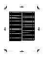
Item
No.
Part Name Q’TY
1FRONT CAP 1
2GRIP (A) 1
3RING 1
4 NEEDLE HOLDER 1
5SPRING (A) 1
6 STOPPER RING 1
7BALL HOLDER 1
8GRIP (B) 1
9 STEEL BALL D6.35 4
10
SEAL LOCK HEX. SOCKET HD. BOLT
M8 × 25
4
11 F RO NT COVER 1
12 O-RING (S-56) 1
13 O-RING (S-32) 1
14 DAMPER 2
15 BOLT M8 1
16 HANDLE HOLDER (B) 2
17 HANDLE HOLDER (A) 2
18 BAND (B) 1
19 GRIP 1
20 SIDE HANDLE ASS'Y 1
21 NEEDLE ROLLER D8 × 20 2
22 RETAINER SLEEVE 1
23 O-RING (S-26) 1
24 SECOND
HAMMER 1
25 HAMMER HOLDER 1
26 DAMPER WASHER 1
27 SLEEVE 1
28 CYLINDER CASE 1
29
HEX. SOCKET HD. BOLT (W/FLANGE)
M8 × 35
4
30 O-RING (1AS-60) 1
31 STRIKER 1
32 O-RING (A) (FPM810) 2
33 PISTON PIN 1
34 PISTON 1
35 CONNECTING ROD 1
36 RETAINING RING FOR D14 SHAFT 1
37 GEAR COVER 1
38 BALL BEARING 6203DDCMPS2L 1
39 BEARING WASHER 1
40 ARMATURE 1
41 FAN GUIDE 1
42 HEX. HD. TAP PING SCREW D5 × 50 2
43 INTERNAL WIRE 235L 1
44 STATOR ASS'Y 1
45 BRUSH TERMINAL 2
46 BEARING WASHER 1
47 BALL BEARING 6201DDCMPS2L 1
48 HOUSING
ASS'Y 1
49 BRUSH CAP 2
50 CARBON BRUSH 1
Item
No.
Part Name Q’TY
51 BRUSH HOLDER 2
52 HEX. SOCKET SET SCREW M5 × 82
53 BEARING HOLDER 1
54 TAPPING SCREW (W/FLANGE) D4 × 16 2
55 DUST SEAL 1
56 TAIL COVER 1
57 TAPPING SCREW (W/FLANGE) D5 × 20 2
58 NEEDLE BEARING (A) (BK1512) 1
59
SEAL LOCK HEX. SOCKET HD. BOLT
M6 × 25
4
60 VINYL TUBE (I.D.9.5 × T0.56 × 85) 1
61 TERMINAL M4.0 1
62 SIDE HANDLE 1
63 MOUNT 1
64 HANDLE BOLT 1
65 BAND 1
66
SEAL LOCK HEX. SOCKET HD. BOLT
M5 × 16
6
67 CRANK COVER 1
68 O-RING (I.D 74.5) 1
69 CRANK SHAFT 1
70 FEATHER KEY 3 × 3 × 10 1
71
SEAL LOCK HEX. SOCKET HD. BOLT
M6 × 50
4
72 BEARING COVER 1
73 BALL BEARING 6204DDCMPS2L 1
74 C RAN K CASE 1
75 OIL SEAL 1
76 DISTANCE RING (C) 1
77 FIRST GEAR 1
78 TAPPING SCREW (W/FLANGE) D4 × 25 4
79 HANDLE COVER 1
80 HANDLE 1
81 SW
(B) 1
82 WASHER M4 1
83 INTERNAL WIRE 1
84 VINYL TUBE 2
85 TERMINAL 1
86 NOISE SUPPRESSOR 1
87 CORD ARMOR 1
88 TUBE (A) 1
89 TAPPING SCREW (W/FLANGE) D4 × 16 2
90 CORD CLIP 1
91 CORD 1
92 NAME PLATE 1
93 TAPPING SCREW D6 × 30 4
94 SUPPORT (B) 1
95 PILLAR TERMINAL 1
96 CONNECTOR 50092 1
97 CONNECTOR 50091 1
502 CASE 1

18

19

008
Code No. C99193631 M
Printed in Malaysia
Hitachi Koki Co., Ltd.
-
 1
1
-
 2
2
-
 3
3
-
 4
4
-
 5
5
-
 6
6
-
 7
7
-
 8
8
-
 9
9
-
 10
10
-
 11
11
-
 12
12
-
 13
13
-
 14
14
-
 15
15
-
 16
16
-
 17
17
-
 18
18
-
 19
19
-
 20
20


Hitachi H 60MC Handling Instructions Manual
- カテゴリー
- パワーツール
- タイプ
- Handling Instructions Manual
他の言語で
- English: Hitachi H 60MC