Delta Electronics Network Device DOP-B クイックスタートガイド
- タイプ
- クイックスタートガイド

5011665702
2008-12-30
HB02

English-1
Preface
Thank you for purchasing DELTA’s DOP-B series. This quick start will be helpful in the installation,
wiring and inspection of Delta HMI. Before using the product, please read this quick start to ensure
correct use. You should thoroughly understand all safety precautions before proceeding with the
installation, wiring and operation. Place this quick start in a safe location for future reference. Please
observe the following precautions:
Install the product in a clean and dry location free from corrosive and inflammable gases or
liquids.
Ensure that all wiring instructions and recommendations are followed.
Ensure that HMI is correctly connected to a ground. The grounding method must comply with
the electrical standard of the country (Please refer to NFPA 70: National Electrical Code, 2005
Ed.).
Do not modify or remove wiring when power is applied to HMI.
Do not touch the power supply during operation. Otherwise, it may cause electric shock.
For the information of HMI software operation, and software installation, please refer to the
HMI software manual.
If you have any questions during operation, please contact our local distributors or Delta sales
representative.
The content of this quick start may be revised without prior notice. Please consult our distributors or
download the most updated version at http://www.delta.com.tw/industrialautomation.
Safety Precautions
Carefully note and observe the following safety precautions when receiving, inspecting, installing,
operating, maintaining and troubleshooting. The following words, DANGER, WARNING and STOP are
used to mark safety precautions when using the Delta’s HMI product. Failure to observe these
precautions may void the warranty!
Installation
¾ Comply with quick start for installation. Otherwise it may cause equipment damage.
¾ Do not install the product in a location that is outside the stated specification for the HMI.
Failure to observe this caution may result in electric shock, fire, or personal injury.
Wiring
¾ Connect the ground terminals to a class-3 ground (Ground resistance should not exceed
100Ω). Improper grounding may result in communication error, electric shock or fire.
Operation
¾ The users should use Delta Screen Editor software to perform editing in Delta's HMI
product. To perform editing and confirming HMI programs without using Delta Screen
Editor software in Delta's HMI product may result in abnormal operation.
¾ Do not modify wiring during operation. Otherwise it may result in electric shock or personal
injury.
¾ Never use a hard or pointed object to hit or strike the screen as doing this may damage the
screen and let the screen has not respond at all, and then cause HMI to work abnormally.

English-2
Maintenance and Inspection
¾ Do not touch any internal or exposed parts of the HMI as electrical shock may result.
¾ Do not remove operation panel while power is on. Otherwise electrical shock may result.
¾ Wait at least 10 minutes after power has been removed before touching any HMI terminals
or performing any wiring and/or inspection as an electrical charge may still remain in the
HMI with hazardous voltages even after power has been removed.
¾ Turn the power off before changing backup battery and check system settings after finishing
change. (all data will be cleared after changing battery).
¾ Be sure the ventilation holes are not obstructed during operation. Otherwise malfunction
may result due to bad ventilation or overheating troubles.
Wiring Method
¾ Remove the terminal block from the HMI before wiring.
¾ Insert only one wire into one terminal on the terminal block.
¾ If the wiring is in error, perform the wiring again with proper tools. Never use force to
remove the terminals or wires. Otherwise, it may result in malfunction or damage.
¾ For the power line that forced to take out, ensure to check wiring again and restart.
Communication Wiring
¾ Comply with communication wiring specification for wiring.
¾ Wiring length should comply with the stated specification for the HMI.
¾ Proper grounding to avoid bad communication quality.
Installation and Storage Conditions
The product should be kept in the shipping carton before installation. In order to retain the warranty
coverage, the HMI should be stored properly when it is not to be used for an extended period of time.
Some storage suggestions are:
Store in a clean and dry location free from direct sunlight.
Store within an ambient temperature range of -20°C to +60°C (-4°F to 140°F).
Store within a relative humidity range of 10% to 90% and non-condensing.
Do not store the HMI in a place subjected to corrosive gases and liquids.
Correctly packaged and placed on a solid and durable surface.
Do not mount the HMI adjacent to heat-radiating elements or in direct sunlight.
Do not mount the HMI in a location subjected to corrosive gases, liquids, or airborne dust or
metallic particles.
Do not mount the HMI in a location where temperatures and humidity will exceed specification.
Do not mount the HMI in a location where vibration and shock will exceed specification.
Do not mount the HMI in a location where it will be subjected to high levels of electromagnetic
radiation.
Installation
Installation Note:
Improper installation will result in malfunction and greatly reduce the life of the HMI. Be sure to
follow the guidelines in this quick start when installing the HMI.
In order to ensure the HMI being well ventilated, make sure that the ventilation holes are not
obstructed and must provide sufficient free space around HMI.

English-3
For use on a flat surface of a Type 4X "Indoor Use Only" enclosure or equivalent.
The allowable thickness of the panel for mounting should be less than 5 mm.
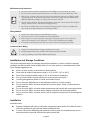
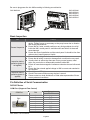
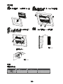
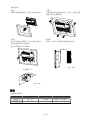
Installation Method:
Step 1:
Ensure to put waterproof gasket into HMI and
then insert the HMI into the panel cutout.
Step 2:
Ensure to insert fasteners into the HMI’s insertion
slots and turn the screw till screws touch panel
cutout.
Step 3:
Turn the screw with less than torque 0.7N.M to
avoid damage to plastic box.
Torque: 6.17lb-inch (0.7N-M)
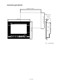
Step 4:
Keep at least 60mm distance from rear of HMI
product to the wall, installation surface or the other
controllers for heat dissipation.
The size of the fastener.
1
6
16.3
2
0
.
4
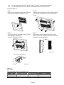
Wiring
Recommended wiring is in the table below:
Type Wire Gauge (AWG) Stripped length Torque
Solid
28 ~ 12 7 ~ 8 mm
5 kg-cm (4.3 lb-in)
Stranded 30 ~ 12 7 ~ 8 mm 5 kg-cm (4.3 lb-in)
Units: mm
Units: mm

English-4
Be sure to plug power line into HMI according to following arrow direction.
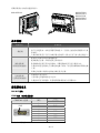
Basic Inspection
Item Content
General Inspection
Periodically inspect the screws of the connection between the HMI and
device. Tighten screws as necessary as they may loosen due to vibration
and varying temperatures.
Ensure that oil, water, metallic particles or any foreign objects do not fall
inside the HMI, control panel or ventilation slots and holes. As these will
cause damage.
Ensure the correct installation and the control panel. It should be free from
airborne dust, harmful gases or liquids.
Inspection before
operation (power is
not applied)
Ensure that all wiring terminals are correctly insulated.
Ensure that all wiring is correct or damage and or malfunction may result.
Visually check to ensure that there are not any unused screws, metal
strips, any conductive or inflammable materials inside HMI.
Ensure to lower electromagnetic interference when devices are influenced
by it.
Ensure that the external applied voltage to HMI is correct and matched to
the controller.
Inspection before
operation (power is
applied)
Check if power LED lights.
Check if the communication among devices is normal.
Please contact our local distributors or Delta sales representative if there
are any abnormal conditions.
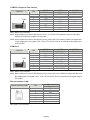
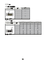
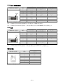
Pin Definition of Serial Communication
DOP-B07 Series
COM1 Port (Supports Flow Control)
Contact
COM Port PIN
RS-232
1
2 RXD
3 TXD
4
5 GND
6
7 RTS
8 CTS
9
Note: Blank = No Connection.
PIN1
DOP-B07S200
DOP-B07S201
DOP-B07S211
DOP-B07E205
DOP-B07E215
DOP-B05S100

English-5
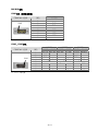
COM2 Port (Supports Flow Control)
MODE1 MODE2 MODE3
COM Port PIN
RS-232 RS-422 RS-485
1 TXD+ D+
2 RXD
3 TXD
4 RXD+
5 GND GND GND
6 TXD- D-
7 RTS
8 CTS
9 RXD-
Note1: Blank = No Connection.
Note2: When COM2 port is used for RS-232 flow control, i.e. RTS and CTS signals are used for flow control,
COM3 port will become incapable of being used.
Note3: When COM2 port is used for RS-422 flow control, please refer to the following COM3 Port signals table
for pin assignments. The signals, RTS+, CTS+, RTS- and CTS- shown in brackets are the signals used
for flow control.
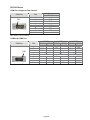
COM3 Port
MODE1 MODE2 MODE3
COM Port PIN
RS-232 RS-422 RS-485
1 TXD+(RTS+) D+
2 RXD
3 TXD
4 RXD+(CTS+)
5 GND GND GND
6 TXD-(RTS-) D-
7
8
9 RXD-(CTS-)
Note1: Blank = No Connection.
Note2: When COM2 port is used for RS-422 flow control, please refer to the COM3 Port signals table above
for
pin assignments
. The signals, RTS+, CTS+, RTS- and CTS- shown in brackets are the signals used for
flow control.
Ethernet Interface (LAN)
Contact
Ethernet Interface (LAN) PIN
Ethernet
1 TX+
2 TX-
3 RX+
4
5
6 RX-
7
8
Note: Blank = No Connection.
PIN1
PIN1

English-6
DOP-B05 Series
COM1 Port (Supports Flow Control)
Contact
COM Port PIN
RS-232
1
2 RXD
3 TXD
4
5 GND
6
7 RTS
8 CTS
9
Note: Blank = No Connection.
COM2 and COM3 Port
MODE1 MODE2 MODE3
COM2 COM3 COM2 COM3 COM2 COM3
COM Port PIN
RS-232 RS-485 RS-485 RS-485 RS-232 RS-422
1 D+ TXD+
2 RXD RXD
3 TXD TXD
4 D+ D+ RXD+
5 GND GND GND
6 D- TXD-
7
8
9 D- D- RXD-
Note: Blank = No Connection.
PIN1
PIN1

English-7
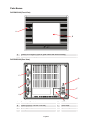
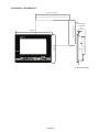
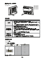
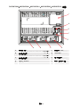
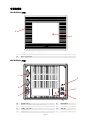
Parts Names
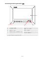
DOP-B05S100 (Front View)
A Power LED Indicator (Lights in green when HMI works normally.)
B Touch Screen / Display
DOP-B05S100 (Rear View)
A Power Input Terminal E USB Host
B COM2 (RS-232 / RS-422 / RS-485) F USB Client
C COM1 (RS-232) G System Key
D Battery Cover
A
B
D
C
B
A
E
F
G

English-8
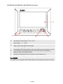
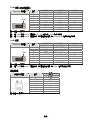
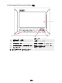
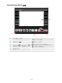
DOP-B07S200 / DOP-B07S201 / DOP-B07E205 (Front View)
A
User-defined Function Keys / System Keys
User-defined Function Keys: F1, F2, F3, F4
System Keys: Y, Z, , SYS
B
Power LED Indicator (Green)
Lights in green when HMI works normally.
C
Left side: Operation LED Indicator (Blue)
The operation LED indicator blinks in blue when either the communication is carried
out or the data is accessing (please refer to the ‘Note’ below for explanation).
Right side: Alarm LED Indicator (Red)
The alarm LED indicator blinks in red when one of the alarms is on.
D Touch Screen / Display
NOTE
The definition of the operation LED indicator (Blue) can be determined by the users freely.
CB
A
D

English-9
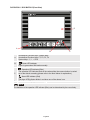
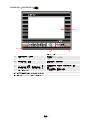
DOP-B07S211 / DOP-B07E215 (Front View)
A
User-defined Function Keys / System Keys
User-defined Function Keys: F1, F2, F3, F4
System Keys: Y, Z, , SYS
B
: Power LED Indicator
Lights in green when HMI works normally.
C
: Operation LED Indicator (Blue)
The operation LED indicator blinks in blue when either the communication is carried
out or the data is accessing (please refer to the ‘Note’ below for explanation).
: Alarm LED Indicator (Red)
The alarm LED indicator blinks in red when one of the alarms is on.
D Touch Screen / Display
NOTE
The definition of the operation LED indicator (Blue) can be determined by the users freely.
C
B
A
D

English-10
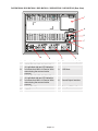
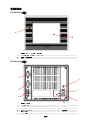
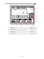
DOP-B07S200 / DOP-B07S201 / DOP-B07S211 / DOP-B07E205 / DOP-B07E215 (Rear View)
A Power Input Terminal F Ethernet Interface (LAN)
B
COM3 (RS-232 / RS-422 / RS-485)
(It is provided with two LED indicators
to indicate that HMI is in Read or Write
status during the communication
process.)
G USB Host
C
COM2 (RS-232 / RS-422 / RS-485)
(It is provided with two LED indicators
to indicate that HMI is in Read or Write
status during the communication
process.)
H Sound Output Interface
D COM1 (RS-232) I Battery / SD Card Cover
E USB Client - -
G
D
C
B
A
I
E
F
H

English-11
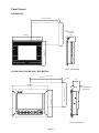
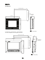
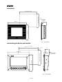
Panel Cut-out
DOP-B05S100
184(7.24")
144(5.67")
43.3
T
172.4+1(6.79"+0.04")
132.4+1(5.21"+0.04")
Note:
T=1.6mm(0.063")~
6mm(0.24")
DOP-B07S200 / DOP-B07S201 / DOP-B07E205
215.0
161.0
T
40.5
196.9 +1.0
142.9 +1.0
4-R3
(8.46")
(6.34")
(7.75" +0.04")
(5.63" +0.04")
NOTE:
T=1.6 mm(0.063")~
6 mm(0.24")
Units: mm (inches)
Units: mm (inches)

English-12
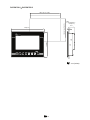
DOP-B07S211 / DOP-B07E215
142.90+1(5.63"+0.04")
196.9+1(7.75" +0.04")
214(8.43")
160(6.3")
Note:
T=1.6mm(0.063")~
6mm(0.24")
39.4
T
Units: mm (inches)

English-13
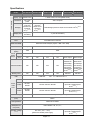
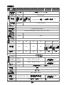
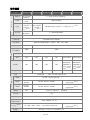
Specifications
MODEL DOP-B05S100 DOP-B07S200 DOP-B07S201 DOP-B07S211 DOP-B07E205 DOP-B07E215
Display Type
5.6” TFT LCD
(65536 colors)
7” Wide Screen TFT LCD (65536 colors)
Resolution
320 x 234
pixels
480 x 234 pixels
Backlight
LED Backlight
(less than
50,000 hours
half-life at
25
o
C)
(Note 1)
CCFL Backlight
(less than
50,000 hours
half-life at
25
o
C)
(Note 1)
LED Backlight (less than 20,000 hours half-life at 25
o
C)
(Note 1)
LCD MODULE
Display Size
5.6" (113.28 x
84.70mm)
7" (154.08 x 86.58mm)
Operation System Windows Base Real Time OS
MCU 32-bit RISC Micro-controller
NOR Flash ROM NOR Flash ROM 4 Mbytes (System: 1MB / User: 3MB)
SDRAM 8Mbytes 16Mbytes
Backup Memory
(Bytes)
128K 256K
Buzzer Multi-Tone Frequency (2K ~ 4K Hz) /85dB
Sound
Effect
Output
AUX N/A N/A N/A N/A Stereo output Stereo output
Ethernet Interface N/A N/A N/A N/A
IEEE 802.3,
IEEE 802.3u
10/100 Mbps
auto-sensing
(has built-in
isolated power
circuit
(Note 3)
)
IEEE 802.3,
IEEE 802.3u
10/100 Mbps
auto-sensing
(has built-in
isolated power
circuit
(Note 3)
)
Memory Card N/A N/A N/A N/A SD Card SD Card
USB 1 USB Host
(Note 2)
Ver 1.1 / 1 USB Client Ver 1.1
COM1 RS-232 (support hardware flow control)
COM2
RS-232 /
RS-485
RS-232 / RS-422 / RS-485
RS-232 / RS-422 / RS-485
(has built-in isolated power
circuit
(Note 3)
)
Serial
COM
Port
COM3
RS-422 /
RS-485
RS-232 / RS-422 / RS-485
RS-232 / RS-422 / RS-485
(has built-in isolated power
circuit
(Note 3)
)
Function Key N/A User defined key x 4 + System key x 4
Perpetual Calendar
(RTC)
Built-in
Cooling Method Natural air circulation
Safety Approval
(Waterproof for
front panel)
IP65 / NEMA4 / CE, UL
(Note 4)
Operation Voltage
(Note 5)
DC +24V (-10% ~ +15%)
(please use isolated power supply)
DC +24V (-10% ~ +15%)
(has built-in isolated power
circuit
(Note 3)
)

English-14
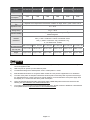
MODEL DOP-B05S100 DOP-B07S200 DOP-B07S201 DOP-B07S211 DOP-B07E205 DOP-B07E215
Voltage Endurance AC500V for 1 minute (between charging (DC24 terminal) and FG terminals)
Power
Consumption
(Note 5)
3.0W 7.5W 4.8W 4.8W 6.5W 6.5W
Backup Battery 3V lithium battery CR2032 x 1
Backup Battery
Life
It depends on the temperature used and the conditions of usage, about 3 years or more at 25
o
C.
Operation Temp.
0
o
C ~ 50
o
C
Storage Temp.
-20
o
C ~ +60
o
C
Ambient Humidity
10% ~ 90% RH [0 ~ 40
o
C], 10% ~ 55% RH [41 ~ 50
o
C]
Pollution Degree 2
Vibration
Resistance
IEC 61131-2 Compliant
5Hz≦f<9Hz = Continuous: 1.75mm / Occasional: 3.5mm
9Hz≦f≦150Hz = Continuous: 0.5g / Occasional: 1.0g
X, Y, Z directions for 10 times
Dimensions
(W) x (H) x (D) mm
184 x 144 x 50 215 x 161 x 50 215 x 161 x 50 215 x 161 x 48 215 x 161 x 50 215 x 161 x 48
Panel Cutout
(W) x (H) mm
172.4 x 142.9 196.9 x 142.9 196.9 x 142.9 196.9 x 142.9 196.9 x 142.9 196.9 x 142.9
Weight Approx. 670g Approx. 880g Approx. 880g Approx. 840g Approx. 920g Approx. 880g
NOTE
1) The half-life of backlight is defined as original luminance being reduced by 50% when the maximum driving
current is supplied to HMI.
2) USB Host port can provide up to 5V/ 500mA of power.
3) The withstand voltage of the isolated power circuit is 1500V peak for 1 minute.
4) DOP-B07S200 this model is UL recognized. Other models are in the process of application to UL certification.
5) The value of the power consumption indicates the electrical power consumed by HMI only without connecting to
any peripheral devices. In order to ensure the normal operation, it is recommended to use a power supply which
the capacity is 1.5 ~2 times the value of the power consumption.
6) Users can download the Screen Editor, the program editor of Delta HMI product and the user manual via the
following link: http://www.delta.com.tw/industrialautomation/.
7) The content of this quick start may be revised without prior notice. Please consult our distributors or download the
most updated version at http://www.delta.com.tw/industrialautomation/.

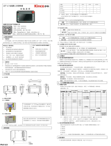
繁中-1
序言
感謝您使用本產品,本人機介面安裝手冊提供 DOP-B 系列人機介面的相關資訊。在使用之前,請您仔細
詳讀本手冊以確保使用上的正確。此外,請妥善將其放置在明顯的地點以便隨時查閱。下列事項在您尚未
讀完本手冊前,請務必遵守:
安裝的環境必須沒有水氣,腐蝕性氣體及可燃性氣體。
接線時,請依接線圖說明施工。
接地工程必須確實實施,接地時須遵照國家現行相關電工法規之規定施行(請參考 NFPA 70:
National Electrical Code, 2005 Ed.)。
在通電時,請勿拆解人機介面或更改配線。
在通電運作時,請勿接觸電源處,以免觸電。
如果您在使用上仍有問題,請洽詢經銷商或者本公司客服中心。由於產品精益求精,當內容規格有所修正
時,請洽詢代理商或至台達網站(http://www.delta.com.tw/industrialautomation/)下載最新版本。
安全注意事項
安裝、配線、操作、維護及檢查時,應隨時注意以下安全注意事項。
安裝注意
¾ 依照手冊指定的方式安裝人機介面,否則可能導致設備損壞。
¾ 禁止將本產品暴露在有水氣、腐蝕性氣體、可燃性氣體等物質的場所下使用,否則可
能會造成觸電或火災。
配線注意
¾ 請將接地端子連接到 class-3(100 Ω以下)接地,接地不良可能會造成通訊異常、觸
電或火災。
操作注意
¾ 人機介面需配合編輯軟體規劃畫面,未經規劃或確認之人機介面可能會導致不正常運
轉結果。
¾ 不得在開啟電源情況下改變配線,否則可能造成觸電或人員受傷。
¾ 請勿以尖銳物品碰觸面板,否則可能導致面板凹陷,進而使人機介面無法正常運作。

繁中-2
保養及檢查
¾ 禁止接觸人機介面內部,否則可能會造成觸電。
¾ 電源啟動時,禁止拆下人機介面面板,否則可能會造成觸電。
¾ 電源關閉 10 分鐘內,不得接觸接線端子,殘餘電壓可能造成觸電。
¾ 更換備用電池時,應切斷電源再進行,並在更換後重新檢查系統設定值。
¾ 人機介面在操作時,排氣孔不可封住,否則人機容易因為散熱不良而造成故障。
配線方法
¾ 配線時請將快速接頭從人機介面的本體上拆下來。
¾ 快速接頭的一個電線插入口,請僅插入一根電線。
¾ 對於錯誤強行拔出電線的動作,請重新檢查連接電線再啟動。
通訊電路的配線
¾ 請依標準規格採用通訊配線線材。
¾ 通訊線材長度需在符合規定內。
¾ 採用正確的接地迴路,以避免通訊不良。
安裝環境條件
本產品在安裝之前必須置於其包裝箱內,若暫時不使用,為了使該產品能夠符合本公司的保固範圍及日後
的維護,儲存時務必注意下列事項:
必須置於無塵垢、乾燥之位置。
儲存位置的環境溫度必須在-20°C to +60°C(-4°F to 140°F)範圍內。
儲存位置的相對溼度必須在 10%到 90%範圍內,且無結露。
避免儲存於含有腐蝕性氣、液體之環境中。
最好適當包裝存放在架子或檯面。
本產品適合的安裝環境包括有:無發高熱裝置之場所﹔無水滴、蒸氣、灰塵及油性灰塵之場所﹔
無腐蝕、易燃性之氣、液體之場所﹔無漂浮性的塵埃及金屬微粒之場所﹔堅固無振動、無電磁雜
訊干擾之場所。
安裝方向與空間
注意事項:
安裝方向必須依規定,否則會造成故障原因。
為了使冷卻循環效果良好,安裝人機介面時,其上下左右與相鄰的物品和擋板(牆)必須保持足夠
的空間,否則會造成散熱不良。
使用於 Type 4X 室內用等級之外殼平面。
安裝面板最大板厚請勿超過 5mm。

繁中-3
安裝示意圖:
步驟一:
請確實將防水墊圈裝入,然後再安裝人機介面
步驟二:
請確實將固定片螺絲組裝入內,然後下方鉤住前蓋
螺絲頭頂住控制箱內側
步驟三:
請以 0.7N-M 扭力鎖緊,切記不可超過此扭力,
否則將造成塑膠外殼的損壞。
扭力: 6.17lb-inch(0.7N-M)
步驟四:
安裝時,人機後方請預留 60mm 散熱空間。
固定螺絲尺寸
1
6
16.3
2
0
.
4
配線
建議配線材料如下:
種類 電源配線(AWG) 剝線長度
扭力
單芯線
28 ~ 12 7 ~ 8 mm
5 kg-cm(4.3 lb-in)
多芯線
30 ~ 12 7 ~ 8 mm
5 kg-cm(4.3 lb-in)
單位:mm
單位:mm

繁中-4
請確實依指示方向將快速接頭裝入
基本檢測
檢測項目 檢測內容
一般檢測
定期檢查人機介面與設備連接處的螺絲是否有鬆動。
排氣孔應避免油、水或金屬粉等異物侵入,且應防止電鑽的切削粉落入人機
介面內。
人機介面若設置於有害氣體或多粉塵的場所,應防止有害氣體與粉塵的侵入。
操作前檢測
(未供應控制電源)
配線端子的接續部請實施絕緣處理。
通訊配線應正確,否則可能發生異常動作。
檢查螺絲或金屬片等導電性物體、可燃性物體是否存在人機介面內。
人機介面附近使用的電子儀器受到電磁干擾時,請使用儀器調校以降低電磁
干擾。
請確定人機介面的供應電源電壓準位是否正確。
運轉前檢測
(已供應控制電源)
電源指示燈是否顯示。
與各設備之間通訊動作是否正常。
人機介面若有異常現象,請洽詢經銷商或者本公司客服中心。
通訊腳位定義
DOP-B07 系列
COM1 定義(支援流量控制)
說明
COM Port 示意圖 腳位
RS-232
1
2 RXD
3 TXD
4
5 GND
6
7 RTS
8 CTS
9
註:空白=不需連接
PIN1
DOP-B07S200
DOP-B07S201
DOP-B07S211
DOP-B07E205
DOP-B07E215
DOP-B05S100

繁中-5
COM2 定義(支援流量控制)
MODE1 MODE2 MODE3
COM Port 示意圖 腳位
RS-232 RS-422 RS-485
1 TXD+ D+
2 RXD
3 TXD
4 RXD+
5 GND GND GND
6 TXD- D-
7 RTS
8 CTS
9 RXD-
註 1:空白=不需連接
註 2:當 COM2 使用 RS-232 流量控制(RTS、CTS 腳位)時,COM3 則無法使用。
註 3:當 COM2 使用 RS-422 流量控制時,其流量控制腳位請參考 COM3 MODE2 括號內的腳位定義。
COM3 定義
MODE1 MODE2 MODE3
COM Port 示意圖 腳位
RS-232 RS-422 RS-485
1 TXD+(RTS+) D+
2 RXD
3 TXD
4 RXD+(CTS+)
5 GND GND GND
6 TXD-(RTS-) D-
7
8
9 RXD-(CTS-)
註 1:空白=不需連接
註 2:當 COM2 使用 RS-422 流量控制時,其流量控制腳位請參考 MODE2 括號內的腳位定義。
網路埠定義
說明
網路埠示意圖 腳位
網路埠
1 TX+
2 TX-
3 RX+
4
5
6 RX-
7
8
註:空白=不需連接
PIN1
PIN1
ページが読み込まれています...
ページが読み込まれています...
ページが読み込まれています...
ページが読み込まれています...
ページが読み込まれています...
ページが読み込まれています...
ページが読み込まれています...
ページが読み込まれています...
ページが読み込まれています...
ページが読み込まれています...
ページが読み込まれています...
ページが読み込まれています...
ページが読み込まれています...
ページが読み込まれています...
ページが読み込まれています...
ページが読み込まれています...
ページが読み込まれています...
ページが読み込まれています...
ページが読み込まれています...
ページが読み込まれています...
ページが読み込まれています...
ページが読み込まれています...
ページが読み込まれています...
-
 1
1
-
 2
2
-
 3
3
-
 4
4
-
 5
5
-
 6
6
-
 7
7
-
 8
8
-
 9
9
-
 10
10
-
 11
11
-
 12
12
-
 13
13
-
 14
14
-
 15
15
-
 16
16
-
 17
17
-
 18
18
-
 19
19
-
 20
20
-
 21
21
-
 22
22
-
 23
23
-
 24
24
-
 25
25
-
 26
26
-
 27
27
-
 28
28
-
 29
29
-
 30
30
-
 31
31
-
 32
32
-
 33
33
-
 34
34
-
 35
35
-
 36
36
-
 37
37
-
 38
38
-
 39
39
-
 40
40
-
 41
41
-
 42
42
-
 43
43


Delta Electronics Network Device DOP-B クイックスタートガイド
- タイプ
- クイックスタートガイド
他の言語で
関連論文
その他のドキュメント
-
Delta DOP-110DS HMI Panel Type 10.1 Inch TFT LCD 取扱説明書
-
-
Kinco GH150E ユーザーマニュアル
-
Kinco Green Series ユーザーマニュアル
-
Contec CPS-MC341-ADSC1-111 取扱説明書
-
 Kinco SZ7 ユーザーマニュアル
-
Philips DDNG232 ユーザーマニュアル
-
WEG CFW500 インストールガイド
-
Korenix JetCon 2201-w Quick Installation Manual
-
Kinco IoT Series ユーザーマニュアル
