
Quick Installation Guide
CFW500 Frequency Inverter
1 SAFETY INSTRUCTIONS
This quick installation guide contains the basic information necessary to commission the CFW500. It has been
written to be used by qualified personnel with suitable training or technical qualification for operating this type of
equipment. The personnel shall follow all the safety instructions described in this manual defined by the local
regulations. Failure to comply with the safety instructions may result in death, serious injury, and/or equipment
damage.
2 SAFETY WARNINGS IN THIS GUIDE AND IN THE PRODUCT
DANGER!
The procedures recommended in this warning aim at protecting the user against death, serious
injuries and considerable material damages.
ATTENTION!
The procedures recommended in this warning aim at preventing material damages.
NOTE!
The information mentioned in this warning is important for the proper understanding and good
operation of the product.
High voltages present.
Components sensitive to electrostatic discharges.
Do not touch them.
The connection to the protection grounding is required (PE).
Connection of the shield to the grounding.
3 PRELIMINARY RECOMMENDATIONS
DANGER!
Always disconnect the general power supply before changing any electric component associated
to the inverter. Many components may remain loaded with high voltages and/or moving (fans), even
after the AC power supply input is disconnected or turned off. Wait for at least ten minutes in order
to guarantee the full discharge of the capacitors. Always connect the grounding point of the inverter
to the protection grounding.
NOTE!
Frequency Inverter may interfere with other electronic equipment. Follow the precautions
recommended in manual available for download on the website: www.weg.net.
NOTE!
It is not the intention of this guide to present all the possibilities for the application of the CFW500,
as well as WEG cannot take any liability for the use of the CFW500 which is not based on this guide.
For further information about installation, full parameter list and recommendations, visit the website
www.weg.net.
Do not execute any applied potential test on the inverter!
If necessary, contact WEG.
ATTENTION!
Electronic boards have components sensitive to electrostatic discharges.
Do not touch directly on components or connectors. If necessary, first touch the grounding point of
the inverter, which must be connected to the protection earth (PE) or use a proper grounding strap.
DANGER!
Crushing Hazard
In order to ensure safety in load lifting applications, electric and/or mechanical devices must be
installed outside the inverter for protection against accidental fall of load.
DANGER!
This product was not designed to be used as a safety element. Additional measures must be taken
so as to avoid material and personal damages.
The product was manufactured under strict quality control, however, if installed in systems where
its failure causes risks of material or personal damages, additional external safety devices must
ensure a safety condition in case of a product failure, preventing accidents.
ATTENTION!
The operation of this equipment requires detailed installation and operation instructions provided in
the user's manual, programming manual and communication manuals, available for download on
the website: www.weg.net.
4 ABOUT THE CFW500
The frequency inverter CFW500 is a high-performance product which allows the speed and torque control of
three-phase induction motors.
5 NOMENCLATURE
Table 1: Nomenclature of the inverters CFW500
Product
and
Series
Identification of the Model
Brake
Protection
Rate
Conducted
Emission
Level
Safety
Functions
Hardware
Version
Special
Software
Version
Frame
Size
Rated
Current
Nº of
Phases
Rated
Voltage
Ex.: CFW500 A 02P6 T 4 NB 20 C2 --- --- ---
Available options
CFW500
Refer to Table 2.2 to the CFW500
user’s manual, available for download
on the website: www.weg.net
Blank =
no safety
functions
Blank =
standard
NB = without dynamic braking Sx =
special
software
DB = with dynamic braking Y2 = with
safety
functions
(STO and
SS1-t,
IEC/EN
61800-5-2)
Blank = standard
plug-in module
20 = IP20
H00 = without plug-in
N1 = cabinet Nema1 (type 1 as per UL) (protection rate
according to standard IEC IP20)
Blank = it does not meet the levels of standards
for conducted emission
C2 or C3 = as per category 2 (C2) or 3 (C3) of
IEC/EN 61800-3, with internal RFI filter
NOTE!
For models with a special software version (Sx in the smart code) and for specific applications, refer
to the application manual available for download on www.weg.net.
6 IDENTIFICATION LABEL
Production order
Rated input data
(voltage, current
and frequency)
Serial number
Manufacturing date
Rated output data
(voltage, current and
frequency)
WEG stock item
Model (Smart code
of the inverter)
CFW500A02P6T4NB20C2
SERIAL#: 1324567890
03H
OP.: 876 54 321
MAT.: 1234 5678
LINE
LINEA
REDE
OUTPUT
SALIDA
SAÍDA
200 - 240 Vac 0... REDE/LINE
1~ 8,8A XX
3~ 19A XX
3~ XX 16A XX
50-60 HzX 0-300 HzX
MADE IN BRAZIL
HECHO EN BRASIL
FABRICADO NO BRASIL
7 894171 190065
(a) For frame sizes A to E
CFW500F77P0T4DB20
FREQUENCY
INVERTER
CFW500
MAT.: 14609374 SERIAL#:
OP.: 999999999
LINE
LINEA
REDE
380 - 480 Vac
3~ 64,7 A
3~ 81,6 A
50/60 Hz
Hz
FABRICADO NO BRASIL
HECHO EN BRASIL
MADE IN BRAZIL
MANUFACTURER: "WEG DRIVES &
CONTROLS - AUTOMAÇÃO LTDA"
AV. PREFEITO WALDEMAR GRUBBA, 3000
CP420, CEP 89256-900 / JARAGUÁ
DO SUL - SC
A (HD)
A (ND)
VAC
OUTPUT
SALIDA
SAÍDA
0 - REDE
3~ 77,0 A
61,0 A
0-500 Hz
48 0
Model (Smart code
of the inverter)
Rated input data
(voltage, current and
frequency)
Production order Manufacturing date
WEG stock item
Serial number
Rated output data
(voltage, current and
frequency)
5232469094927
(b) For frame size F
Figure 1: (a) and (b) Description of the identification label on the CFW500
7 RECEIVING AND STORAGE
The CFW500 is supplied in a cardboard package up to frame size E. Models with larger enclosures are packed in a
wooden box. On this package, there is an identification label which is the same as the one attached to the side of
the inverter.
Follow the procedures below to open the package of models from frame size F up:
1. Place the package on a table with the help of two people.
2. Open the package.
3. Remove the cardboard or styrofoam protection.
Check if:
The identification of the CFW500 matches the model purchased.
Any damages occurred during transportation.
Report any damage immediately to the carrier.
If the CFW500 is not installed soon, store it in a clean and dry location (temperature between -25 °C and 60 °C (-77 ºF
and 140 ºF)), with a cover to prevent dust accumulation inside it.
ATTENTION!
When the inverter is stored for a long period, it becomes necessary to perform the capacitor
reforming. Refer to the procedure recommended in the user’s manual, available for download on
the website: www.weg.net.
8 INSTALLATION AND CONNECTION
8.1 ENVIRONMENTAL CONDITIONS:
Avoid:
Direct exposure to sunlight, rain, high humidity or sea-air.
Inflammable or corrosive liquids or gases.
Excessive vibration.
Dust, metallic particles or oil mist.
Environmental conditions permitted for the operation of the inverter:
Temperature around the inverter from -10 ºC (14 ºF) to the nominal temperature.
Inverters with frame sizes A to E: for temperatures surrounding the inverter higher than the specifications in Table
B.4 in the user's manual CFW500, available for download on the website: www.weg.net, it is necessary to apply
of 2 % of current derating for each Celsius degree, limited to an increase of 10 ºC (50 ºF).
Inverters with frame size F: for temperatures around the inverter higher than the specification indicated in Table B.5
in the user's manual, available for download on the website: www.weg.net, it is necessary to derate the current
by 1 % for each degree Celsius up to 50 °C (122 °F) and by 2 % for each degree Celsius up to 60 °C (140 °F).
Air relative humidity: 5 % to 95 % non-condensing.
Maximum altitude: up to 1000 m (3.300 ft) - nominal conditions.
1000 m to 4000 m (3.300 ft to 13.200 ft) - 1 % of current derating for each 100 m (328 ft) above 1000 m of altitude.
From 2000 m to 4000 m (6.600 ft to 13.200 ft) above sea level - maximum voltage reduction (240 V for 200...240 V
models, 480 V for 380...480 V models and 600 V for 500...600 V models) of 1.1 % for each 100 m (330 ft) above
2000 m (6.600 ft).
Pollution degree: 2 (according to EN 50178 and UL 508C), with non-conductive pollution. Condensation must not
originate conduction through the accumulated residues.
8.2 POSITIONING AND MOUNTING
The external dimensions and the drilling for the mounting, as well as the net weight (mass) of the inverter are
presented in Figure 2.
Mount the inverter in the upright position on a flat and vertical surface. First, put the screws on the surface where
the inverter will be installed, install the inverter and then tighten the screws observing the maximum torque for the
screws indicated in Figure 2.
Allow the minimum clearances indicated in Figure 3, in order to allow the cooling air circulation. Do not install heat
sensitive components right above the inverter.
P
L
A
B
H
Side viewFront viewView of the mounting base
D
C
Frame
Size
A B C D H L P Weight
Mounting
Bolt
Recommended
Torque
mm
(in)
mm
(in)
mm
(in)
mm
(in)
mm
(in)
mm
(in)
mm
(in)
kg (lb) N.m (Ibf.in)
A
50.0
(1.97)
175.0
(6.89)
11.9
(0.47)
7.2
(0.28)
189.0
(7.4 4)
75.0
(2.95)
150.0
(5.91)
0.8 (1.76)
(1)
M4 2 (17.7 )
B
75.0
(2.95)
185.0
(7.30 )
11.8
(0,46)
7.3
(0.29)
199.0
(7.8 3 )
100.0
(3.94)
160.0
(6.30)
1.2 (2.65)
(1)
M4 2 (17.7 )
C
100.0
(3.94)
195.0
(7.70 )
16.7
(0.66)
5.8
(0.23)
210.0
(8.27)
135.0
(5.31)
165.0
(6.50)
2 (4.4) M5 3 (26.5)
D
125.0
(4.92)
290.0
(11.41)
27. 5
(1.08)
10.2
(0.40)
306.6
(12.07)
180.0
(7.0 8 )
166.5
(6.55)
4.3 (0.16) M6 4.5 (39.82)
E
150.0
(5.90)
330.0
(12.99)
34.0
(1.34)
10.6
(0.42)
350.0
(13.78)
220.0
(8.66)
191.5
(7.5 4)
10 (22.05) M6 4.5 (39.82)
F
200.0
(7.87)
525.0
(20.67)
42.5
(1.67)
15.0
(0.59)
550.0
(21.65)
300.0
(11.81)
254.0
(10)
26 (57. 3) M8 19 (168.16)
Dimension tolerance: ±1.0 mm (±0.039 in).
(1) This value refers to the heaviest weight of the frame size.
Figure 2: Inverter dimensions for mechanical installation
(c) Flange mounting - standard inverter
a3
d3
b3
e3
Øc3
(a) Surface mounting
(b) DIN rail mounting (Only Sizes A, B, C)
C
D
B
A
(d) Minimum ventilation free spaces
Frame
Size
a3 b3 c3 d3 e3 A B C D
Torque
Par
(1)
mm (in) mm (in) M mm (in) mm (in) mm (in) mm (in) mm (in) mm (in)
N.m. (lbf.
in)
A - - - - - 15.0 (0.59) 40.0 (1.57) 30.0 (1.18) 10.0 (0.39)
(2)
-
B - - - - - 35.0 (1.38) 50.0 (1.97) 40.0 (1.57) 15.0 (0.59)
(2)
-
C - - - - - 40.0 (1.57) 50.0 (1.97) 50.0 (1.97) 3 0.0 (1.18) -
D - - - - - 40.0 (1.57) 50.0 (1.97) 50.0 (1.97) 40.0 (1.57) -
E - - - - - 110.0 (4.33) 130.0 (5.11) 50.0 (1.97) 40.0 (1.57) -
F
275.0
(10.83)
517.0
(20.35)
M8
288.0
(11.34)
488.0
(19.21)
110.0 (4.33) 130.0 (5.11) 10.0 (0.39) 3 0.0 (1.18) 20 (177)
Dimension tolerance: ±1.0 mm (±0.039 in).
(1) Recommended torque for fixing the inverter (valid for c3).
(2) It is possible to mount inverters side by side without lateral free space (D = 0), however with maximum ambient temperature of 40 ºC (104 ºF).
Figure 3: (a) to (d) Mechanical installation data (surface mounting and minimum ventilation free espaces)
ATTENTION!
When installing two or more inverters vertically, respect the minimum clearance A + B (as per
Figure 3) and provide an air deflecting plate so that the heat rising up from the bottom inverter
does not affect the top inverter.
Provide independent conduits for the physical separation of signal, control, and power cables
(refer to the Chapter 9 ELECTRICAL INSTALLATION).
9 ELECTRICAL INSTALLATION
DANGER!
The following information is merely a guide for proper installation. Comply with applicable local
regulations for electrical installations.
Make sure the power supply is disconnected before starting the installation.
The CFW500 must not be used as an emergency stop device. Provide other devices for that
purpose.
ATTENTION!
Integral solid state short circuit protection does not provide branch circuit protection. Branch circuit
protection must be provided in accordance with applicable local codes.
9.1 IDENTIFICATION OF THE POWER TERMINALS AND GROUNDING POINTS
The power terminals can be of different sizes and configurations, depending on the model of the inverter, according
to Table 2. The maximum torque of the power terminals and grounding points must be checked in Table 2.
Table 2: Power terminals, grounding points and recommended tightening torque
Frame
Size
Power Supply
Recommended Torque
Grounding Points Power Terminals
N.m Lbf.in N.m Lbf.in
A
200...240 V 0.5 4.34 0.5 4.34
380...480 V
0.5 4.34 0.5 4.34
B
200...240 V
0.5 4.34 0.5 4.34
380...480 V 0.5 4.34 0.5 4.34
C
200...240 V 0.5 4.34 1.7 15
380...480 V 0.5 4.34 1.8 15.93
500...600V 0.5 4.34 1.0 8.68
D
200...240 V 0.5 4.34 2.4 21.24
380...480 V
0.5 4.34 1.76 15.57
E
200...240 V 0.5 4.34 3.05 27
380...480 V 0.5 4.34 3.05 27
F 380...480 V 0.5 8.85 5.5 48.68
Description of the power terminals:
L/L1, N/L2 and L3 (R, S, T): AC power supply. Some models of voltage 200-240 V (see option of models in Table 5)
can operate in 2 or 3 phases (single-phase/ three-phase inverters) without derating of the rated current. In this case,
the AC power supply can be connected to two of the three input terminals without distinction. For the single-phase
models only, the power voltage must be connected to L/L1 and N/L2.
U, V, W: connection for the motor.
-UD: negative pole of the voltage of the DC Link.
+UD: positive pole of the voltage of the DC Link.
BR: connection of the brake resistor.
DCR: connection to the external DC Link inductor (optional). Only available for models 28 A, 33 A, 47 A and
56 A / 200-240 V and 24 A, 31 A, 39 A and 49 A / 380-480 V.
9.2 POWER AND GROUNDING WIRING, CIRCUIT BREAKERS AND FUSES
ATTENTION!
Use proper cable lugs for the power and grounding connection cables. Refer to Table 5 for
recommended wiring, circuit breakers and fuses.
Keep sensitive equipment and wiring at a minimum distance of 0.25 m from the inverter and from
the cables connecting the inverter to the motor.
It is not recommended the use of mini circuit breakers (MDU), because of the actuation level
of the magnet.
ATTENTION!
Residual Current Device (RCD):
When installing an RCD to guard against electrical shock, only devices with a trip current of 300
mA should be used on the supply side of the inverter.
Depending on the installation (motor cable length, cable type, multimotor configuration, etc.),
the RCD protection may be activated. Contact the RCD manufacturer for selecting the most
appropriate device to be used with inverters.
NOTE!
The wire gauges listed in Table 5 are orientative values. Installation conditions and the maximum
permitted voltage drop must be considered for the proper wiring sizing.
In order to meet UL requirements, use ultra fast (for frame sizes A, B and C), and use fuse type J
or circuit breaker (for frame sizes D and E) fuses at the inverter supply with a current not higher
than the values presented in Figure 5.
9.3 POWER CONNECTIONS
T
PE
WU
V
W
U
V
PE
Input
power
supply
Fuses
Disconnecting
switch
Shield
-UD DCR+UDBR
PE
TS
R
V
PE
U
W
R
S
T
PE
Fuses
Disconnecting
switch
Shield
(*) The power terminals -Ud, BR and +Ud are not available in models of frame size A.
PE
(*)
PE
V
PE
U
W
R
S
+Ud
BR
-Ud
T
(a) Frame sizes A, B, C and F
(b) Frame sizes D and E
U V W
U
V
W
PE
Input
power
supply
R
S
Figure 4: (a) and (b) Power and grounding connections
9.3.1 Input Connections
DANGER!
Provide a disconnect device for the inverter power supply. This device must cut off the power
supply whenever necessary (during maintenance for instance).
ATTENTION!
The power supply that feeds the inverter must have a grounded neutral. In case of IT networks, follow
the instructions described in the user's manual, available for download on the website: www.weg.net.
NOTE!
The input power supply voltage must be compatible with the inverter rated voltage.
Power factor correction capacitors are not needed at the inverter input (L/L1, N/L2, L3 or R, S, T)
and must not be installed at the output (U, V, W).
Power supply capacity
Suitable for use in circuits capable of delivering not more than 30.000 Arms symmetrical (200 V, 480 V or 600 V),
when protected by fuses as specified in Table 5.
English
15219001

7. Power up the input: close the disconnecting switch.
8. Check the success of the powering up:
The display of the HMI indicates:
10.1 STARTUP
10.1.1 V/f Control Type (P0202 = 0)
Step Indication on the Display/Action Step Indication on the Display/Action
1
Monitoring mode
Press the key ENTER/MENU to enter 1st level of
programming mode
2
The PARAM group is selected, press the keys or
until selecting the STARTUP group
3
When the STARTUP group is selected
Press the key ENTER/MENU
4
The parameter "P0317 – Oriented Start-up" is then
selected, press the ENTER/MENU to get into the
parameter content
5
Change the parameter P0317 to "1 - Yes", by using
the key
6
If necessary, press ENTER/MENU to modify the
content of "P0202 - Control Type" for P0202 = 0 (V/f)
7
When the desired value is reached, press ENTER/
MENU to save the modification
Press the key for the next parameter
8
If necessary, modify the content of "P0401 - Motor
Rated Current"
Press the key for the next parameter
9
If necessary, modify the content of "P0402 - Motor
Rated Speed"
Press the key for the next parameter
10
If necessary, modify the content of "P0403 - Motor
Rated Frequency"
Press the key for the next parameter
11
To end the Start-up routine, press the key BACK/
ESC
To return to the monitoring mode, press the key
BACK/ESC again
11 TECHNICAL SPECIFICATIONS
11.1 POWER DATA
Power Supply:
Voltage Tolerance: -15 % to +10 % of nominal voltage.
Frequency: 50/60 Hz (48 Hz to 62 Hz).
Phase imbalance: ≤ 3 % of the rated phase-to-phase input voltage.
Overvoltage according to Category III (IEC/EN 61010/UL 508C).
Transient voltage according to Category III.
Maximum of 10 connections (power up cycles - ON/OFF) per hour (1 every 6 minutes).
Typical efficiency: ≥ 97 %.
12 CONSIDERED STANDARDS
Table 4: Considered standards
Safety
standards
UL 508C - power conversion equipment.
Note: Suitable for Installation in a compartment handling conditioned air.
UL 840 - insulation coordination including clearances and creepage distances for electrical
equipment.
IEC/EN 61800-5-1 - safety requirements electrical, thermal and energy.
EN 50178 - electronic equipment for use in power installations.
IEC/EN 60204-1 - safety of machinery. Electrical equipment of machines. Part 1: general
requirements.
Note: for the machine to comply with this standard, the manufacturer of the machine is
responsible for installing an emergency stop device and equipment to disconnect the input
power supply.
IEC/EN 60146 (IEC 146) - semiconductor converters.
IEC/EN 61800-2 - adjustable speed electrical power drive systems - part 2: general requirements
- rating specifications for low voltage adjustable frequency AC power drive systems.
Electromagnetic
compatibility (EMC)
standards
IEC/EN 61800-3 - adjustable speed electrical power drive systems - part 3: EMC product
standard including specific test methods.
CISPR 11 - industrial, scientific and medical (ISM) radio-frequency equipment - electromagnetic
disturbance characteristics - limits and methods of measurement.
IEC/EN 61000-4-2 - electromagnetic compatibility (EMC) - part 4: testing and measurement
techniques - section 2: electrostatic discharge immunity test.
IEC/EN 61000-4-3 - electromagnetic compatibility (EMC) - part 4: testing and measurement
techniques - section 3: radiated, radio-frequency, electromagnetic field immunity test.
IEC/EN 61000-4-4 - electromagnetic compatibility (EMC) - part 4: testing and measurement
techniques - section 4: electrical fast transient/burst immunity test.
IEC/EN 61000-4-5 - electromagnetic compatibility (EMC) - part 4: testing and measurement
techniques - section 5: surge immunity test.
IEC/EN 61000-4-6 - electromagnetic compatibility (EMC)- part 4: testing and measurement
techniques - section 6: immunity to conducted disturbances, induced by radio-frequency fields.
Mechanical
construction
standards
EN 60529 - degrees of protection provided by enclosures (IP code).
UL 50 - enclosures for electrical equipment.
IEC/EN 60721-3-3 – classification of environmental conditions - part 3: classification of
groups of environmental parameters and their severities - section 3: stationary use at weather
protected locations level 3m4.
13 CERTIFICATIONS
Certifications
(*)
Notes
UL and cUL E184430
CE
IRAM
C-Tick
EAC
(*) For updated information on certifications, please contact WEG.
14 LIST OF MODELS CFW500 SERIES
Table 5: List of models of CFW500 series, main electrical specifications
Inverter
Number of Input Phases
Power Supply
Rated Voltage
Frame Size
Output
Rated
Current
Maximum
Motor
Recommended Fuse
Circuit Breaker
Power Wire
Size
Grounding
Wire Size
Dynamic Braking
I²t [A²s] Current [A]
Recommended
WEG aR Fuse
Maximum
Current
Recommended
Resistor
Braking rms
Current
Power Wire
Size for DC+
and BR
Terminals
[Vrms]
HD HD
[A] WEG mm² (AWG) mm² (AWG)
(I
max
)
[A]
[Ω] [A]
mm²
(AWG)
[Arms] [HP/ kW]
CFW500A01P6S2
1
220...240
A
1.6 0.25/0.18 373 20
(2)
FNH00-20K-A 5.5 MPW18-3-D063 1.5 (16) 2.5 (14)
Dynamic braking not
available
CFW500A02P6S2 2.6 0.5/0.37 373 20
(2)
FNH00-20K-A 9.0 MPW18-3-U010 1.5 (16) 2.5 (14)
CFW500A04P3S2 4.3 1/0.75 373 25
(2)
FNH00-25K-A 13.5 MPW18-3-U016 1.5 (16) 2.5 (14)
CFW500A07P0S2 7.0 2/1.5 800 40
(2)
FNH00-40K-A 25 MPW40-3-U025 4.0 (12) 4.0 (12)
CFW500B07P3S2
1 B
7.3 2/1.5 450 40
(2)
FNH00-40K-A 25 MPW40-3-U025 2.5 (14) 4.0 (12) 10 39 7 2.5 (14)
CFW500B10P0S2 10 3/2.2 450 63
(2)
FNH1-63K-A 32 MPW40-3-U032 4.0 (12) 4.0 (12) 15 27 11 2.5 (14)
CFW500A01P6B2
1/3
A
1.6 0.25/0.18 680 20
(2)
FNH00-20K-A 5.5/2.5
(1)
MPW18-3-D063 / MPW18-3-D025
(1)
1.5 (16) 2.5 (14)
Dynamic braking not
available
CFW500A02P6B2 2.6 0.5/0.37 680 20
(2)
FNH00-20K-A 9.0/4.0
(1)
MPW18-3-U010 / MPW18-3-U004
(1)
1.5 (16) 2.5 (14)
CFW500A04P3B2 4.3 1/0.75 680 25/20
(1) (2)
FNH00-25K-A / FNH00-20K-A
(1)
14/6.3
(1)
MPW18-3-U016 / MPW18-3-D063
(1)
1.5 (16) 2.5 (14)
CFW500B07P3B2
B
7.3 2/1.5 450 40/20
(1) (2)
FNH00-40K-A / FNH00-20K-A
(1)
25/12
(1)
MPW40-3-U025 / MPW18-3-U016
(1)
2.5/1.5 (14/16)
(1)
4.0 (12) 10 39 7 2.5 (14)
CFW500B10P0B2 10 3/2.2 450 63/25
(1) (2)
FNH1-63K-A / FNH00-25K-A
(1)
32/16
(1)
MPW40-3-U032 / MPW18-3-U016
(1)
4.0/2.5 (12/14)
(1)
4.0 (12) 15 27 11 2.5 (14)
CFW500A07P0T2
3
A
7.0 2/1.5 680 20
(2)
FNH00-20K-A 10 MPW18-3-U010 1.5 (16) 2.5 (14)
Dynamic braking not
available
CFW500A09P6T2 9.6 3/2.2 1250 25
(2)
FNH00-25K-A 16 MPW18-3-U016 2.5 (14) 2.5 (14)
CFW500B16P0T2 B 16 5/3.7 1000 40
(2)
FNH00-40K-A 25 MPW40-3-U025 4.0 (12) 4.0 (12) 20 20 14 4.0 (12)
CFW500C24P0T2 C 24 7.5/5.5 1000 63
(2)
FNH00-63K-A 40 MPW40-3-U040 6.0 (10) 4.0 (12) 26 15 13 6.0 (10)
CFW500D28P0T2
D
28 10/7.5 2750 63
(2)
FNH00-63K-A 40 MPW40-3-U040 10 (8) 10 (8) 38 10 18 10 (8)
CFW500D33P0T2 33 12.5/9.2 2750 80
(3)
FNH00-80K-A 50 MPW65-3-U050 10 (8) 10 (8) 45 8.6 22 10 (8)
CFW500D47P0T2 47 15/11 2750 100
(3)
FNH00-100K-A 65 MPW65-3-U065 10 (8) 10 (8) 45 8.6 22 10 (8)
CFW500E56P0T2 E 56 20/15 6600 125
(3)
FNH00-125K-A 80 MPW80-3-U080 16 (6) 16 (6) 95 4.7 48 16 (6)
CF W500A01P0T4
380...480
A
1.0 0.25/0.18 450 20
(2)
FNH00-20K-A 1.6 MPW18-3-D016 1.5 (16) 2.5 (14)
Dynamic braking not
available
CF W500A01P6T4 1.6 0.5/0.37 450 20
(2)
FNH00-20K-A 2.5 MPW18-3-D025 1.5 (16) 2.5 (14)
CF W500A02P6T4 2.6 1.5/1.1 450 20
(2)
FNH00-20K-A 4.0 MPW18-3-U004 1.5 (16) 2.5 (14)
CFW500A04P3T4 4.3 2/1.5 450 20
(2)
FNH00-20K-A 6.3 MPW18-3-D063 1.5 (16) 2.5 (14)
CF W500A06 P1T4 6.1 3/2.2 450 20
(2)
FNH00-20K-A 10 MPW18-3-U010 1.5 (16) 2.5 (14)
CF W500B02P6T4
B
2.6 1.5/1.1 450 20
(2)
FNH00-20K-A 4.0 MPW18-3-U004 1.5 (16) 2.5 (14) 6 127 4.5 1.5 (16)
CF W500B04P3T4 4.3 2/1.5 450 20
(2)
FNH00-20K-A 6.3 MPW18-3-D063 1.5 (16) 2.5 (14) 6 127 4.5 1.5 (16)
CFW500B06P5T4 6.5 3/2.2 450 20
(2)
FNH00-20K-A 10 MPW18-3-U010 1.5 (16) 2.5 (14) 8 100 5.7 2.5 (14)
CFW500B10P0T4 10 5/3.7 1000 25
(2)
FNH00-25K-A 16 MPW18-3-U016 2.5 (14) 2.5 (14) 16 47 11.5 2.5 (14)
CF W500C14P0T4
C
14 7.5/5.5 1000 35
(2)
FNH00-35K-A 20 MPW40-3-U020 4.0 (12) 4.0 (12) 24 33 14 6.0 (10)
CF W500C16P0T4 16 10 / 7.5 1000 35
(2)
FNH00-35K-A 25 MPW40-3-U025 4.0 (12) 4.0 (12) 24 33 14 6.0 (10)
CF W500D24P0T4
D
24 15/11 1800 60
(3)
FNH00-63K-A 40 MPW65-3-U040 6.0 (10) 6.0 (10) 34 22 21 10 (8)
CF W500D31P0T4 31 20/15 1800 60
(3)
FNH00-63K-A 50 MPW65-3-U050 10 (8) 10 (8) 48 18 27 10 (8)
CF W500E39P0T4
E
39 25/18.5 2100 80
(3)
FNH00-80K-A 50 MPW65-3-U050 10 (8) 10 (8) 78 8.6 39 10 (8)
CF W500E49P0T4 49 30/22 13000 100
(3)
FNH00-100K-A 65 MPW65-3-U065 10 (8) 10 (8) 78 8.6 39 10 (8)
CFW500C01P7T5
500...600 C
1.7 1/0.75 495 20
(2)
FNH00-20K-A 2.5 MPW18-3-D025 1.5 (16) 2.5 (14) 1.2 825 0.6 1.5 (16)
CFW500C03P0T5 3.0 2/1.5 495 20
(2)
FNH00-20K-A 4 MPW18-3-U004 1.5 (16) 2.5 (14) 2.6 392 1.3 1.5 (16)
CFW500C04P3T5 4.3 3/2.2 495 20
(2)
FNH00-20K-A 6.3 MPW18-3-D063 1.5 (16) 2.5 (14) 4 249 2 1.5 (16)
CFW500C07P0T5 7. 0 5/3.7 495 20
(2)
FNH00-20K-A 10 MPW18-3-U010 2.5 (14) 2.5 (14) 6 165 3 1.5 (16)
CFW500C10P0T5 10 7.5/5.5 495 25
(2)
FNH00-20K-A 16 MPW18-3-U016 2.5 (14) 2.5 (14) 9 110 4.5 1.5 (16)
CFW500C12P0T5 12 10 / 7.5 495 25
(2)
FNH00-20K-A 16 MPW18-3-U016 2.5 (14) 2.5 (14) 12.2 82 6.1 1.5 (16)
(1) The first number refers to the single-phase and the second to the three-phase supply.
(2) In order to comply with UL508C standard, use UL ultra fast fuses, for frame sizes A, B, and C.
(3) In order to comply with UL508C standard, use fuses UL type J for frame sizes D and E.
Table 6: List of models of CFW500 series, main electrical specifications - frame size F
Inverter
Number of Input Phases
Power Supply Rated
Voltage
Frame Size
Output Rated Current Maximum Motor
Recommended Fuse
Circuit Breaker
Power Wire
Size
Grounding
Wire Size
Dynamic Braking
I²t [A²s] Current [A]
Recommended
WEG aR Fuse
Maximum
Current
Recommended
Resistor
Braking rms
Current
Power Wire Size
for DC+ and BR
Terminals
ND HD ND HD
[Vrms] [Arms] [Arms] [HP/kW] [HP/kW] [A] WEG mm² (AWG) mm² (AWG)
(I
max
)
[A]
[Ω] [A]
mm²
(AWG)
CF W500F77P0T4 3
380....480 F
77 61 50/37 40/30 3050 100 FNH00-100K-A 80 MDW-C80-3 25 (3) 16 (4) 66.7 12 43 10 (6)
CFW500F88P0T4 3 88 73 60/45 50/37 3050 125 FNH00-125K-A 100 MDW-C100-3 35 (2) 16 (4) 129 6.2 63 25 (4)
CFW500F0105T4 3 105 88 75/55 60/45 5200 160/125
(1)
FNH1-160K-A / FNH1-125K-A
(2)
125 ACW160H-U125-3 50/35 (1/2)
(1)
16 (4) 129 6.2 63 25 (4)
(1) The first number refers to ND application and the second to HD application.
(2) The first number refers to the ND application (use 2 fuses in series per phase) and the second one to the HD application.
Document: 10007168908 / 00
9.3.2 Dynamic Braking
NOTE!
The dynamic braking is available from frame size B for the CFW500. For installation information,
refer to Item 3.2.3.4 Dynamic Braking of the user’s manual, available for download on the website:
www.weg.net.
9.3.3 Output Connections
ATTENTION!
The inverter has an electronic motor overload protection that must be adjusted according to the
driven motor. When several motors are connected to the same inverter, install individual overload
relays for each motor.
The motor overload protection available in the CFW500 is in accordance with the UL508C standard.
Note the following information:
1. Trip current equal to 1.2 times the motor rated current (P0401).
2. When parameters P0156, P0157 and P0158 (Overload current at 100 %, 50 % and 5 % of the rated
speed, respectively) are manually set, the maximum value to meet the condition 1 is 1.1 x P0401.
ATTENTION!
If a disconnect switch or a contactor is installed at the power supply between the inverter and the
motor, never operate it with the motor turning or with voltage at the inverter output.
The characteristics of the cable used to connect the motor to the inverter, as well as its interconnection and routing,
are extremely important to avoid electromagnetic interference in other equipment and not to affect the life cycle of
windings and bearings of the controlled motors.
Keep motor cables away from other cables (signal cables, sensor cables, control cables, etc.), according to Item
9.3.6 Cable Separation Distance.
Connect a fourth cable between the motor ground and the inverter ground.
9.3.4 Grounding Connections
DANGER!
The inverter must be connected to a protection grounding (PE).
Use grounding wiring with a gauge at least equal to that indicated in Table 5.
The maximum tightening torque of the grounding connections is of 1.7 N.m (15 lbf.in).
Connect the grounding points of the inverter to a specific grounding rod, or specific grounding
point or to the general grounding point (resistance ≤ 10 Ω).
The neuter conductor that powers up the inverter must be solidly grounded; however, this
conductor must not be used to ground the inverter.
Do not share the grounding wiring with other equipment that operate with high currents (e.g. high
power motors, soldering machines, etc.).
9.3.5 Control Connections
The control connections (analog input/output, digital input/output and interface RS485) must be performed
according to the specification of the connector of the plug-in module connected to the CFW500. Refer to the guide
of the plug-in module in the package of the product. The typical functions and connections for the CFW500-IOS
standard plug-in module are shown in Figure 5.
DI1
DI2
DI3
DI4
+24 V
DO1-RL-NA
DO1-RL-F
DO1-RL-NF
GND
GND
A-RS485 (-)
B-RS485
(+)
GND (485)
rpm
+10 V
AI1
GND
AO1
>300 Ω
+24 V
≥5 kΩ
DO2-
TR
Connector Description
(**)
Top connection
1 DI1
Digital input 1
3 DI2
Digital input 2
(*)
5 DI3
Digital input 3
7 DI4
Digital input 4
9 +24 V
Power supply +24 Vdc
11 DO1-RL-NA
Digital output 1 (NO contact of relay 1)
13 DO1-RL-C
Digital output 1 (common point of relay 1)
15 DO1-RL-NF
Digital output 1 (NC contact of relay 1)
17 GND
Reference 0 V
Bottom connection
2 AO1 Analog output 1
4 GND Reference 0 V
6 AI1 Analog input 1
8 +10 V Reference +10 Vdc for potentiometer
10 DO2-TR Digital output 2 (transistor)
12 GND Reference 0 V
14 RS485 - A RS485 (terminal A)
16 RS485 - B
RS485 (terminal B)
18 GND (485) GND (RS485)
(*) The digital input 2 (DI2) can also be used as input in frequency (FI). For further details
refer to the programming manual of the CFW500, available for download on the website:
www.weg.net.
(**) For further information about the technical specifications, refer to Chapter 8 in the
CFW500 user’s manual, available for download on the website: www.weg.net.
Figure 5: Signals of the connector of the CFW500-IOS plug-in module
For the correct connection of the control, use:
1. Gauge of the cables: 0.5 mm² (20 AWG) to 1.5 mm² (14 AWG).
2. Maximum torque: 0.5 N.m (4.50 lbf.in).
3. Wiring of the plug-in module connector with shielded cable and separated from the other wiring (power, command
in 110 V / 220 Vac, etc), according to Item 9.3.6 Cable Separation Distance.
4. Relays, contactors, solenoids or coils of electromechanical brake installed close to the inverters may occasionally
generate interference in the control circuitry. To eliminate this effect, RC suppressors (with AC power supply) or
freewheel diodes (with DC power supply) must be connected in parallel to the coils of these devices.
5. When using the external HMI, the cable that connects to the inverter must be separated from the other cables in
the installation, keeping a minimum distance of 10 cm.
6. When using analog reference (AI1) and the frequency oscillates (problem of electromagnetic interference),
interconnect the GND of the connector of the plug-in module to the inverter grounding connection.
9.3.6 Cable Separation Distance
Table 3: Cable separation distance
Inverter Output
Rated Current
Length
of the Cable(s)
Minimum Separation
Distance
≤ 24 A
≤ 100 m (330 ft)
> 100 m (330 ft)
≥ 10 cm (3.94 in)
≥ 25 cm (9.84 in)
≥ 28 A
≤ 30 m (100 ft)
> 30 m (100 ft)
≥ 10 cm (3.94 in)
≥ 25 cm (9.84 in)
10 PREPARATION AND POWERING UP
DANGER!
Always disconnect the general power supply before making any connection.
1. Check if the power, grounding and control connections are correct and firm.
2. Remove all materials left from the inside of the inverter or drive.
3. Check if the motor connections and if the motor current and voltage match the inverter.
4. Mechanically uncouple the motor from the load. If the motor cannot be uncoupled, be sure that the turning in any
direction (clockwise or counterclockwise) will not cause damages to the machine or risk of accidents.
5. Close the covers of the inverters or drive.
6. Measure the voltage of the input power supply and check if it is within the permitted range, as presented in Chapter
11 TECHNICAL SPECIFICATIONS.

Guia de Instalación Rápida
CFW500 Inversor de
Frecuencia
1 INSTRUCCIONES DE SEGURIDAD
Esta guía de instalación rápida contiene las informaciones básicas necesarias para la puesta en funcionamiento del
CFW500. El mismo fue desarrollado para ser utilizado por personas con capacitación o calificación técnica adecuadas
para operar este tipo de equipo. Estas personas deben seguir las instrucciones de seguridad definidas por las normas
locales. No seguir las instrucciones de seguridad puede derivar en riesgo de muerte y/o daños al equipo.
2 AVISOS DE SEGURIDAD EN EL GUÍA Y EL PRODUCTO
¡PELIGRO!
Los procedimentos recomendados en este aviso tienen como objetivo proteger al usuario contra
muerte, heridas graves y daños materiales considerables.
¡ATENCIÓN!
Los procedimentos recomendados en este aviso tienen como objetivo proteger al usuario contra
muerte, heridas graves y daños materiales considerables.
¡NOTA!
Las informaciones mencionadas en este aviso son importantes para el correcto entendimento y
bom funcionamiento del producto.
Tensiones elevadas presentes.
Componentes sensibles a descarga electrostática.
No tocarlos.
Conexión obligatoria a tierra de protección (PE).
Conexión del blindaje a tierra.
3 RECOMENDACIONES PRELIMINARES
¡PELIGRO!
Siempre desconecte la alimentación general antes de manipular cualquier componente eléctrico
asociado al convertidor. Muchos componentes pueden permanecer cargados con altas tensiones
y/o en movimiento (ventiladores), incluso después de que la entrada de alimentación CA sea
desconectada o apagada. Aguarde por lo menos 10 minutos para garantizar la total descarga de
los condensadores. Siempre conecte el punto de aterramiento del convertidor a tierra de
protección (PE).
¡NOTA!
Los convertidores de frecuencia pueden interferir en otros equipos electrónicos. Siga los cuidados
recomendados en el manual disponible para download en el sitio: www.weg.net.
¡NOTA!
No es la intención de este guía agotar todas las posibilidades de aplicación del CFW500, ni la WEG
puede asumir ninguna responsabilidad por el uso del CFW500 que no esté basado en este guía.
Para más informaciones sobre instalación, lista completa de parámetros y recomendaciones,
consulte el sitio www.weg.net.
¡No ejecute ningún ensayo de tensión aplicada en el convertidor!
En caso que sea necesario consulte a WEG.
¡ATENCIÓN!
Las tarjetas electrónicas poseen componentes sensibles a descargas electrostáticas.
No toque directamente sobre los componentes o conectores. En caso que sea necesario, toque
antes en el punto de aterramiento del convertidor que debe estar conectado a tierra de protección
(PE) o utilice una pulsera de aterramiento adecuada.
¡PELIGRO!
Riesgo de aplastamiento
Para garantizar la seguridad en aplicaciones de elevación de carga, se deben instalar dispositivos de
seguridad eléctricos y/o mecánicos, externos al convertidor, para protección contra caída accidental
de carga.
¡PELIGRO!
Este producto no fue proyectado para ser utilizado como elemento de seguridad. Para evitar daños
materiales y a la vida humana, se deben implementar medidas adicionales. El producto fue fabricado
siguiendo un riguroso control de calidad, no obstante, si es instalado en sistemas donde su falla
ofrezca riesgo de daños materiales, o a personas, los dispositivos de seguridad adicionales externos
deben garantizar una situación segura, ante la eventual falla del producto, evitando accidentes.
¡ATENCIÓN!
La operación de este equipo requiere instrucciones de instalación y operación detalladas,
suministradas en el manual del usuario, manual de programación y manuales de comunicación ,
disponibles para download en el sitio: www.weg.net.
4 SOBRE EL CFW500
El convertidor de frecuencia CFW500 es un producto de alta performance que permite el control de velocidad y
torque de motores de inducción trifásicos.
5 NOMENCLATURA
Tabla 1: Nomenclatura de los convertidores CFW500
Pr o d u c t o
y Serie
Identificación del Modelo
Frenado
Grado de
Protección
Nivel de
Emisión
Conducida
Funciones
de
Seguridad
Versión
de
Hardware
Versión
de
Software
Especial
Tamaño
Corriente
Nominal
N° de
Fases
Tensión
Nominal
Ej.: CFW500 A 02P6 T 4 NB 20 C2 --- --- ---
Opciones disponibles
CFW500
Consulte la Tabla 2.2 del manual de
usuario del CFW500, disponible para
download en el sitio: www.weg.net
En blanco =
sin funciones
de seguridad
En
blanco =
estándar
NB = sin frenado reostático Sx =
software
especial
DB = con frenado reostático Y2 = con
funciones de
seguridad
(STO y SS1-t,
conforme
IEC/EN
61800-5-2)
En blanco = módulo
plug-in estándar
20 = IP20
H00 = sem plug-in
N1 = gabinete Nema1 (tipo 1 según UL) (grado de
protección de acuerdo con norma IEC IP20)
En blanco = no atiende niveles de normas de
emisión conducida
C2 o C3 = según categoría 2 (C2) o 3 (C3) de la
IEC/EN 61800-3, con filtro RFI interno
¡NOTA!
Para modelos con versión de software especial, Sx en el código inteligente, y para aplicaciones
específicas, consulte el manual de aplicación disponible para download en el sitio www.weg.net.
6 ETIQUETAS DE IDENTIFICACIÓN
Orden de
producción
Datos nominales de entrada
(tensión, corriente y
frecuencia)
Número de serie
Fecha de fabricación
Datos nominales de salida
(tensión, corriente y frecuencia)
Ítem de stock WEG
Modelo (Código Inteligente
del convertidor)
CFW500A02P6T4NB20C2
SERIAL#: 1324567890
03H
OP.: 876 54 321
MAT.: 1234 5678
LINE
LINEA
REDE
OUTPUT
SALIDA
SAÍDA
200 - 240 Vac 0... REDE/LINE
1~ 8,8A XX
3~ 19A XX
3~ XX 16A XX
50-60 HzX 0-300 HzX
MADE IN BRAZIL
HECHO EN BRASIL
FABRICADO NO BRASIL
7 894171 190065
(a) Para los tamaños A y E
CFW500F77P0T4DB20
FREQUENCY
INVERTER
CFW500
MAT.: 14609374 SERIAL#:
OP.: 999999999
LINE
LINEA
REDE
380 - 480 Vac
3~ 64,7 A
3~ 81,6 A
50/60 Hz
Hz
FABRICADO NO BRASIL
HECHO EN BRASIL
MADE IN BRAZIL
MANUFACTURER: "WEG DRIVES &
CONTROLS - AUTOMAÇÃO LTDA"
AV. PREFEITO WALDEMAR GRUBBA, 3000
CP420, CEP 89256-900 / JARAGUÁ
DO SUL - SC
A (HD)
A (ND)
VAC
OUTPUT
SALIDA
SAÍDA
0 - REDE
3~ 77,0 A
61,0 A
0-500 Hz
48 0
Modelo (Código Inteligente
do inversor)
Datos nominales de
entrada (tensión,
corriente y frecuencia)
Orden de producción
Fecha de fabricación
Ítem de stock WEG
Número de serie
Datos nominales de
salida (tensión, corriente
y frecuencia)
5232469094927
(b) Para el tamaño F
Figura 1: (a) y (b) Descripción de las etiquetas de identificación en el CFW500
7 RECEPCIÓN Y ALMACENAMIENTO
El CFW500 es suministrado embalado en caja de cartón hasta los modelos del tamaño E. Los modelos en
gabinetes mayores son embalados en caja de madera. En la parte externa de este embalaje existe una etiqueta de
identificación que es la misma que está fijada en la lateral del convertidor.
Siga los procedimientos de abajo para abrir el embalaje de modelos a partir del tamaño F:
1. Coloque el embalaje sobre una mesa, con el auxilio de dos personas.
2. Abra el embalaje.
3. Retire la protección de cartón o isopor.
Verifique si:
La etiqueta de identificación del CFW500 corresponde al modelo comprado.
Ocurrieron daños durante el transporte.
En caso que sea detectado algún problema, contacte inmediatamente la transportadora.
Si el CFW500 no es instalado inmediatamente, almacénelo en un lugar limpio y seco (temperatura entre -25 ºC y
60 ºC) con una cobertura para evitar la entrada de polvo en el interior del convertidor.
¡ATENCIÓN!
Quando el convertidor es almacenado por largos períodos de tiempo es necesario hacer el
“reforming” de los condensadores. Consulte el procedimiento recomendado en www.weg.net.
8 INSTALACIÓN Y CONEXIÓN
8.1 CONDICIONES AMBIENTALES:
Evitar:
Exposición directa a rayos solares, lluvia, humedad excesiva o brisa marina.
Gases o líquidos explosivos o corrosivos.
Vibración excesiva.
Polvo, partículas metálicas o de aceite suspendidos en el aire.
Condiciones ambientales permitidas para funcionamiento:
Temperatura alrededor del convertidor desde - 10 ºC hasta la temperatura nominal.
Convertidores de los tamaños A a E: para temperaturas alrededor del convertidor mayor que lo especificado en
la Tabla B.4 en el manual del usuario, disponible para download en el sitio: www.weg.net, es necesario aplicar
reducción de la corriente de 2 % para cada grado Celsius limitando el incremento en 10 ºC.
Convertidores del tamaño F: para temperatura alrededor del convertidor mayor que lo especificado en la Tabla B.5
del manual del usuario, disponible para download en el sitio: www.weg.net, es necesario aplicar reducción de
la corriente de 1 % para cada grado Celsius hasta 50 ºC y 2 % para cada grado Celsius hasta 60 ºC.
Humedade relativa del aire: de 5 % a 95 % sin condensación.
Altitud máxima: hasta 1000 m - condiciones nominales.
De 1000 m a 4000 m - reducción de la corriente de 1 % para cada 100 m encima de 1000 m de altitud.
De 2000 metros a 4000 m por encima del nivel del mar - aplicar 1,1 % de reducción de la tensión máxima (240 Vca
para los modelos 200...240 Vca, 480 Vca para los modelos 380...480 Vca y 600 V para los modelos 500...600 V) para
cada 100 metros por encima de 2000 metros.
Grado de contaminación: 2 (según EN 50178 y UL 508C), con contaminación no conductiva. La condensación
no debe causar conducción de los residuos acumulados.
8.2 POSICIONAMIENTO E FIJACIÓN
Las dimensiones externas y de perforación para fijación, así como el peso líquido (masa) del convertidor son
presentados en la Figura 2.
Instale el convertidor en la posición vertical en una superficie plana. Primeramente, coloque los tornillos en la
superficie donde el convertidor será instalado, instale el convertidor y entonces apriete los tornillos respetando el
torque máximo de apriete de los mismos indicado en la Figura 2.
Deje como mínimo los espacios libres indicados en la Figura 3, de forma de permitir circulación de aire de
refrigeración. No ponga componentes sensibles al calor encima del convertidor.
P
L
A
B
H
Vista lateralVista frontalVista de la base de fijación
D
C
Tamaño
A B C D H L P Peso
Tornillo de
Fijación
Torque
Recomendado
mm
(in)
mm
(in)
mm
(in)
mm
(in)
mm
(in)
mm
(in)
mm
(in)
kg (lb) N.m (Ibf.in)
A
50,0
(1,97)
175,0
(6,89)
11,9
(0,47)
7,2
(0,28)
189,0
(7,4 4)
75,0
(2,95)
150,0
(5,91)
0,8 (1,76)
(1)
M4 2 (17,7)
B
75,0
(2,95)
185,0
(7,30)
11,8
(0,46)
7,3
(0,29)
199,0
(7,83)
100,0
(3,94)
160,0
(6,30)
1,2 (2,65)
(1)
M4 2 (17,7)
C
100,0
(3,94)
195,0
(7,70 )
16,7
(0,66)
5,8
(0,23)
210,0
(8,27)
135,0
(5,31)
165,0
(6,50)
2 (4,4) M5 3 (26,5)
D
125,0
(4,92)
290,0
(11,41)
27, 5
(1,08)
10,2
(0,40)
306,6
(12,07)
180,0
(7,0 8 )
166,5
(6,55)
4,3 (0,16) M6 4,5 (39,82)
E
150,0
(5,90)
330,0
(12,99)
34,0
(1,34)
10,6
(0,42)
350,0
(13,78)
220,0
(8,66)
191,5
(7,54 )
10 (22,05) M6 4,5 (39,82)
F
200,0
(7,87)
525,0
(20,67)
42,5
(1,67)
15,0
(0,59)
550,0
(21,65)
300,0
(11,81)
254,0
(10)
26 (57, 3 ) M8 19 (168,16)
Tolerancia de las cotas: ±1,0 mm (±0,039 in).
(1) Este valor se refiere al mayor peso para el mismo tamaño.
Figura 2: Dimensiones del convertidor para la instalación mecánica
(c) Montaje en flange - convertidor estándar
(a) Montaje en superfície
(b) Montaje en riel DIN (Solamente Tamaños A, B, C)
(d) Espacios libres mínimos para ventilación
a3
d3
b3
e3
Øc3
C
D
B
A
Tamaño
a3 b3 c3 d3 e3 A B C D
Torque
Par
(1)
mm (in) mm (in) M mm (in) mm (in) mm (in) mm (in) mm (in) mm (in)
N,m,
(lbf,in)
A
- - - - -
15,0 (0,59) 40,0 (1,57) 30,0 (1,18) 10,0 (0,39)
(2) -
B
- - - - -
35,0 (1,38) 50,0 (1,97) 40,0 (1,57) 15,0 (0,59)
(2) -
C
- - - - -
40,0 (1,57) 50,0 (1,97) 50,0 (1,97) 30,0 (1,18)
-
D
- - - - -
40,0 (1,57) 50,0 (1,97) 50,0 (1,97) 40,0 (1,57)
-
E
- - - - -
110,0 (4,33) 130,0 (5,11) 50,0 (1,97) 40,0 (1,57)
-
F
275,0
(10,83)
517, 0
(20,35)
M8
288,0
(11,34)
488,0
(19,21)
110,0 (4,33) 130,0 (5,11) 10,0 (0,39) 30,0 (1,18) 20 (177)
Tolerancia de las cotas: ±1,0 mm (±0,039 in).
(1) Torque recomendado para fijación del convertidor (válido para c3).
(2) Es posible montar convertidores lado a lado sin espacio lateral (D = 0), al menos con la temperatura ambiente máxima de 40 ºC.
Figura 3: (a) a (d) Dados para instalación mecánica (montaje en superficie y espacios libres mínimos para ventilación)
¡ATENCIÓN!
Cuando un convertidor es instalado encima de otro, use la distancia mínima A + B (según la Figura 3)
y desvíe del convertidor superior el aire caliente proveniente del convertidor que está abajo.
Prever electroducto o canales independientes para la separación física de los conductores de
señal, control y potencia (consulte el Capítulo 9 INSTALACIÓN ELÉCTRICA).
9 INSTALACIÓN ELÉCTRICA
¡PELIGRO!
Las informaciones a continuación tienen la intención de servir como guía para ejecutar una
instalación correcta. Siga también las normas de instalaciones eléctricas aplicables.
Asegúrese que la red de alimentación está desconectada antes de iniciar las conexiones.
El CFW500 no debe ser utilizado como mecanismo para parada de emergencia. Utilize otros
mecanismos adicionales para este fin.
¡ATENCIÓN!
La potencia de cortocircuito del convertidor de frecuencia no proporciona protección de
cortocircuito del circuito alimentador. La protección de cortocircuito del circuito alimentador debe
ser contemplada conforme las normativas locales aplicables.
9.1 IDENTIFICIÓN DE LOS BORNES DE POTENCIA Y PUNTOS DE ATERRAMIENTO
Los bornes de potencia pueden ser de diferentes tamaños y configuraciones, dependiendo del modelo del
convertidor, según la Tabla 2. El torque máximo de apriete de los bornes de potencia y puntos de aterramiento debe
ser verificado en la Tabla 2.
Tabla 2: Bornes de potencia, puntos de aterramiento y torques de apriete recomendado
Tamaño
Tensión
Nominal
Torque Recomendado
Puntos de Aterramiento Bornes de Potencia
N.m Lbf.in N.m Lbf.in
A
200...240 V 0,5 4,34 0,5 4,34
380...480 V
0,5 4,34 0,5 4,34
B
200...240 V
0,5 4,34 0,5 4,34
380...480 V 0,5 4,34 0,5 4,34
C
200...240 V 0,5 4,34 1,7 15
380...480 V 0,5 4,34 1,8 15,93
500...600V 0,5 4,34 1,0 8,68
D
200...240 V 0,5 4,34 2,4 21,24
380...480 V
0,5 4,34 1,76 15,57
E
200...240 V 0,5 4,34 3,05 27
380...480 V 0,5 4,34 3,05 27
F 380...480 V 0,5 8,85 5,5 48,68
Descripción de los bornes de potencia:
L/L1, N/L2 y L3 (R, S, T): red de alimentación CA. Algunos modelos de la línea de tensión 200-240 V (ver opción
de modelos en la Tabla 5) pueden operar en 2 o 3 fases (inversores monofásico/trifásico) sin reducción de la
corriente nominal. La tensión de alimentación CA, en este caso puede ser conectada en 2 de los 3 terminales de
entrada. Para los modelos solamente monofásicos, la tensión de alimentación debe ser conectada en L/L1 y N/L2.
U, V, W: conexión para el motor.
-UD: polo negativo de la tensión del Link DC.
+UD: polo positivo de la tensión del Link DC.
BR: conexión del resistor de frenado.
DCR: conexión para el inductor del Link DC externo (opcional). Solamente disponibles para los modelos 28 A, 33 A,
47 A y 56 A / 200-240 V y 24 A, 31 A, 39 A y 49 A/ 380-480 V.
9.2 CABLEADO DE POTENCIA, ATERRAMIENTO, DISYUNTORES Y FUSIBLES
¡ATENCIÓN!
Utilice terminales adecuados para los cables de las conexiones de potencia y aterramiento.
Consulte la Tabla 5 para cableado, disyuntores y fusibles recomendados.
Apartar los equipamientos y cableados sensibles a 0,25 m del convertidor y de los cables de
conexión entre convertidor y motor.
No es recomendable utilizar los mini disyuntores (MDU), debido al nivel de actuación del magnético.
¡ATENCIÓN!
Interruptor diferencial residual (DR):
Cuando utilizado en la alimentación del convertidor deberá presentar corriente de actuación de 300 mA.
Dependiendo de las condiciones de instalación, como longitud y tipo del cable del motor, accionamiento
multimotor, etc., podrá ocurrir la actuación del interruptor DR. Verificar con el fabricante el tipo más
adecuado para operar con convertidores.
¡NOTA!
Los valores dimensionales del alambre de la Tabla 5 son apenas ilustrativos. Para el correcto
dimensionamiento del cableado, se deben tomar en cuenta las condiciones de instalación y la
máxima caída de tensión permitida.
Para conformidad con la norma UL, utilizar fusibles ultrarápidos (para los tamaños A, B y C), y
utilizar fusible tipo J o el disyuntor (para los tamaños D y E) en la alimentación del convertidor
con corriente no mayor que los valores de la Tabla 5.
9.3 CONEXIONES DE POTENCIA
T
PE
WU
V
W
U
V
PE
Red
Fusibles
Seccionadora
Blindaje
-UD DCR+UDBR
PE
TS
R
V
PE
U
W
R
S
T
PE
Fusibles
Seccionadora
Blindaje
(*) Los bornes de potencia -Ud, BR y +Ud no están disponibles en los modelos del Tamaño A
PE
(*)
PE
V
PE
U
W
R
S
+Ud
BR
-Ud
T
(a) Tamaños A, B, C y F
(b) Tamaños D y E
U V W
U
V
W
PE
Red
R
S
Figura 4: (a) y (b) Conexiones de potencia y aterramiento
9.3.1 Conexiones de Entrada
¡PELIGRO!
Prevea un dispositivo para seccionamiento de la alimentación del convertidor. Éste debe seccionar
la red de alimentación para el convertidor cuando sea necesario (por ejemplo: durante trabajos de
mantenimiento).
¡ATENCIÓN!
La red que alimenta al convertidor debe tener el neutro sólidamente aterrado. En caso de red IT, siga las
instrucciones descritas en el manual del usuario disponible para download en el sitio: www.weg.net.
¡NOTA!
La tensión de red debe ser compatible con la tensión nominal del convertidor.
No son necesarios condensadores de corrección del factor de potencia en la entrada (L/L1, N/
L2, L3 o R, S, T) y no deben ser conectados en la salida (U, V, W).
Capacidad de la red de alimentación
Adecuado para uso en circuitos con capacidad de entregar un máximo de 30.000 Arms simétricos (200 V,
480 V o 600 V), cuando está protegido por fusibles, conforme la especificación de la Tabla 5.
Español
15219001

7. Energice la entrada: cierre la llave seccionadora de entrada.
8. Verifique si la energización fue efectivamente realizada:
El display de la HMI indica:
10.1 PUESTA EN FUNCIONAMIENTO
10.2 TIPO DE CONTROL V/F (P0202 = 0)
Seq Indicación en el Display/Acción Seq Indicación en el Display/Acción
1
Modo monitoreo
Presione la tecla ENTER/MENU para entrar en
el primer nivel del modo programación
2
El grupo PARAM está seleccionado, presione
las teclas o hasta seleccionar el grupo
STARTUP
3
Cuando seleccionado el grupo STARTUP
presione la tecla ENTER/MENU
4
El parámetro "P0317 – Start-up Orientado"
está seleccionado, presione ENTER/MENU para
acceder al contenido del parámetro)
5
Modifique el contenido del parámetro P0317 para
"1 - Si", usando la tecla
6
Si fuera necesario, presione ENTER/MENU
para para alterar el contenido de "P0202 - Tipo
de Control" para P0202 = 0 (V/f)
7
Cuando alcance el valor deseado, presione
ENTER/MENU para guardar la alteración
Presione la tecla para el próximo parámetro
8
Si fuera necesario altere el contenido de "P0401
- Corriente Nominal Motor"
Presione la tecla para el próximo parámetro
9
Si fuera necesario altere el contenido de "P0402
- Rotación Nominal Motor"
Presione la tecla para el próximo parámetro
10
Si fuera necesario altere el contenido de "P0403
- Frecuencia Nominal Motor"
Presione la tecla para el próximo parámetro
11
Para finalizar la rutina de Start-up, presione la
tecla BACK/ESC
Para retornar al modo monitoreo, presione la tecla
BACK/ESC nuevamente
11 ESPECIFICACIONES TÉCNICAS
11.1 DATOS DE POTENCIA
Fuente de alimentación:
Tolerancia de tensión: -15 % a +10 % de la tensión nominal.
Frecuencia: 50/60 Hz (48 Hz a 62 Hz).
Desbalanceo de fase: 3 % de la tensión de entrada fase-fase nominal.
Sobretensiones de acuerdo con Categoría III (IEC/EN 61010/UL 508C).
Tensiones transientes de acuerdo con la Categoría III.
Máxima de 10 interrupciones en la energización por hora (1 a cada 6 minutos - lado red eléctrica).
Rendimiento típico: ≥ 97 %.
12 NORMAS CONSIDERADAS
Tabla 4: Normas consideradas
Normas de
seguridad
UL 508C - power conversion equipment
Nota: Suitable for Installation in a compartment handling conditioned air
UL 840 - insulation coordination including clearances and creepage distances for electrical equipment
IEC/EN 61800-5-1 - safety requirements electrical, thermal and energy
EN 50178 - electronic equipment for use in power installations
IEC/EN 60204-1 - safety of machinery. Electrical equipment of machines. Part 1: general requirements
Nota: para tener una máquina en conformidad co esa norma, el fabricante de la máquina es
responsable por la instalación de un dispositivo de parada de emergencia y un equipamiento para
seccionamiento de la red
IEC/EN 60146 (IEC 146) - semiconductor converters
IEC/EN 61800-2 - adjustable speed electrical power drive systems - part 2: general requirements
- rating specifications for low voltage adjustable frequency AC power drive systems
Normas de
compatibilidad
electromagnética
IEC/EN 61800-3 - adjustable speed electrical power drive systems - part 3: EMC product standard
including specific test methods
CISPR 11 - industrial, scientific and medical (ISM) radio-frequency equipment - electromagnetic
disturbance characteristics - limits and methods of measurement
IEC/EN 61000-4-2 - electromagnetic compatibility (EMC) - part 4: testing and measurement techniques
- section 2: electrostatic discharge immunity test
IEC/EN 61000-4-3 - electromagnetic compatibility (EMC) - part 4: testing and measurement techniques
- section 3: radiated, radio-frequency, electromagnetic field immunity test
IEC/EN 61000-4-4 - electromagnetic compatibility (EMC) - part 4: testing and measurement techniques
- section 4: electrical fast transient/burst immunity test
IEC/EN 61000-4-5 - electromagnetic compatibility (EMC) - part 4: testing and measurement techniques
- section 5: surge immunity test
IEC/EN 61000-4-6 - electromagnetic compatibility (EMC)- part 4: testing and measurement techniques
- section 6: immunity to conducted disturbances, induced by radio-frequency fields
Normas de
construcción
mecánica
IEC/EN 60529 - degrees of protection provided by enclosures (IP code)
UL 50 - enclosures for electrical equipment
IEC/EN 60721-3-3 – classification of environmental conditions - part 3: classification of groups
of environmental parameters and their severities - section 3: stationary use at weather protected
locations level 3m4
13 CERTIFICACIONES
Certificaciones
(*)
Observaciones
UL e cUL E184430
CE
IRAM
C-Tick
EAC
(*) Para información actualizada sobre certificaciones consultar a WEG.
14 RELACIÓN DE MODELOS DE LÍNEA CFW500
Tabla 5: Relación de modelos de línea CFW500, especificaciones eléctricas principales
Convertidor
N° de Fases de
Alimentación
Tensión Nominal
de Alimentación
Tamaño
Corriente
Salida
Nominal
Motor
Máximo
Fusible Recomendado
Disyuntor
Calibre de
los Cables de
Potencia
Calibre del
Cable de
Aterramiento
Frenado Reostático
I²t [A²s]
Corriente
[A]
Fusible aR WEG
Recomendado
Corriente
Máxima
Resistor
Recomendado
Corriente
Eficaz de
Frenado
Calibre de los
Cables +UD
y BR
[Vrms]
HD HD
[A] WEG mm² (AWG) mm² (AWG)
(I
max
)
[A]
[Ω] [A]
mm²
(AWG)
[Arms] [HP/ kW]
CFW500A01P6S2
1
220...240
A
1,6 0,25/0,18 373 20
(2)
FNH00-20K-A 5,5 MPW18-3-D063 1,5 (16) 2,5 (14)
Frenado reostático no disponible
CFW500A02P6S2 2,6 0,5/0,37 373 20
(2)
FNH00-20K-A 9,0 MPW18-3-U010 1,5 (16) 2,5 (14)
CFW500A04P3S2 4,3 1/0,75 373 25
(2)
FNH00-25K-A 13,5 MPW18-3-U016 1,5 (16) 2,5 (14)
CFW500A07P0S2 7,0 2/1,5 800 40
(2)
FNH00-40K-A 25 MPW40-3-U025 4,0 (12) 4,0 (12)
CFW500B07P3S2
1 B
7,3 2/1,5 450 40
(2)
FNH00-40K-A 25 MPW40-3-U025 2,5 (14) 4,0 (12) 10 39 7 2,5 (14)
CFW500B10P0S2 10 3/2,2 450 63
(2)
FNH1-63K-A 32 MPW40-3-U032 4,0 (12) 4,0 (12) 15 27 11 2,5 (14)
CFW500A01P6B2
1/3
A
1,6 0,25/0,18 680 20
(2)
FNH00-20K-A 5,5/2,5
(1)
MPW18-3-D063/MPW18-3-D025
(1)
1,5 (16) 2,5 (14)
Frenado reostático no disponibleCFW500A02P6B2 2,6 0,5/0,37 680 20
(2)
FNH00-20K-A 9,0/4,0
(1)
MPW18-3-U010/MPW18-3-U004
(1)
1,5 (16) 2,5 (14)
CFW500A04P3B2 4,3 1/0,75 680 25/20
(1) (2)
FNH00-25K-A/FNH00-20K-A
(1)
14/6,3
(1)
MPW18-3-U016/MPW18-3-D063
(1)
1,5 (16) 2,5 (14)
CFW500B07P3B2
B
7,3 2/1,5 450 40/20
(1) (2)
FNH00-40K-A/FNH00-20K-A
(1)
25/12
(1)
MPW40-3-U025/MPW18-3-U016
(1)
2,5/1,5 (14/16)
(1)
4,0 (12) 10 39 7 2,5 (14)
CFW500B10P0B2 10 3/2,2 450 63/25
(1) (2)
FNH1-63K-A/FNH00-25K-A
(1)
32/16
(1)
MPW40-3-U032/MPW18-3-U016
(1)
4,0/2,5 (12/14)
(1)
4,0 (12) 15 27 11 2,5 (14)
CFW500A07P0T2
3
A
7,0 2/1,5 680 20
(2)
FNH00-20K-A 10 MPW18-3-U010 1,5 (16) 2,5 (14)
Frenado reostático no disponible
CFW500A09P6T2 9,6 3/2,2 1250 25
(2)
FNH00-25K-A 16 MPW18-3-U016 2,5 (14) 2,5 (14)
CFW500B16P0T2 B 16 5/3,7 1000 40
(2)
FNH00-40K-A 25 MPW40-3-U025 4,0 (12) 4,0 (12) 20 20 14 4,0 (12)
CFW500C24P0T2 C 24 7,5/5,5 1000 63
(2)
FNH00-63K-A 40 MPW40-3-U040 6,0 (10) 4,0 (12) 26 15 13 6,0 (10)
CFW500D28P0T2
D
28 10 / 7, 5 2750 63
(2)
FNH00-63K-A 40 MPW40-3-U040 10 (8) 10 (8) 38 10 18 10 (8)
CFW500D33P0T2 33 12,5/9,2 2750 80
(3)
FNH00-80K-A 50 MPW65-3-U050 10 (8) 10 (8) 45 8,6 22 10 (8)
CFW500D47P0T2 47 15/11 2750 100
(3)
FNH00-100K-A 65 MPW65-3-U065 10 (8) 10 (8) 45 8,6 22 10 (8)
CFW500E56P0T2 E 56 20/15 6600 125
(3)
FNH00-125K-A 80 MPW80-3-U080 16 (6) 16 (6) 95 4,7 48 16 (6)
CF W500A01P0T4
380...480
A
1,0 0,25/0,18 450 20
(2)
FNH00-20K-A 1,6 MPW18-3-D016 1,5 (16) 2,5 (14)
Frenado reostático no disponible
CF W500A01P6T4 1,6 0,5/0,37 450 20
(2)
FNH00-20K-A 2,5 MPW18-3-D025 1,5 (16) 2,5 (14)
CF W500A02P6T4 2,6 1,5/1,1 450 20
(2)
FNH00-20K-A 4,0 MPW18-3-U004 1,5 (16) 2,5 (14)
CFW500A04P3T4 4,3 2/1,5 450 20
(2)
FNH00-20K-A 6,3 MPW18-3-D063 1,5 (16) 2,5 (14)
CF W500A06 P1T4 6,1 3/2,2 450 20
(2)
FNH00-20K-A 10 MPW18-3-U010 1,5 (16) 2,5 (14)
CF W500B02P6T4
B
2,6 1,5/1,1 450 20
(2)
FNH00-20K-A 4,0 MPW18-3-U004 1,5 (16) 2,5 (14) 6 127 4,5 1,5 (16)
CF W500B04P3T4 4,3 2/1,5 450 20
(2)
FNH00-20K-A 6,3 MPW18-3-D063 1,5 (16) 2,5 (14) 6 127 4,5 1,5 (16)
CFW500B06P5T4 6,5 3/2,2 450 20
(2)
FNH00-20K-A 10 MPW18-3-U010 1,5 (16) 2,5 (14) 8 100 5,7 2,5 (14)
CFW500B10P0T4 10 5/3,7 1000 25
(2)
FNH00-25K-A 16 MPW18-3-U016 2,5 (14) 2,5 (14) 16 47 11,5 2,5 (14)
CF W500C14P0T4
C
14 7,5/5,5 1000 35
(2)
FNH00-35K-A 20 MPW40-3-U020 4,0 (12) 4,0 (12) 24 33 14 6,0 (10)
CF W500C16P0T4 16 10/7,5 1000 35
(2)
FNH00-35K-A 25 MPW40-3-U025 4,0 (12) 4,0 (12) 24 33 14 6,0 (10)
CF W500D24P0T4
D
24 15/11 1800 60
(3)
FNH00-63K-A 40 MPW65-3-U040 6,0 (10) 6,0 (10) 34 22 21 10 (8)
CF W500D31P0T4 31 20/15 1800 60
(3)
FNH00-63K-A 50 MPW65-3-U050 10 (8) 10 (8) 48 18 27 10 (8)
CF W500E39P0T4
E
39 25/18,5 2100 80
(3)
FNH00-80K-A 50 MPW65-3-U050 10 (8) 10 (8) 78 8,6 39 10 (8)
CF W500E49P0T4 49 30/22 13000 100
(3)
FNH00-100K-A 65 MPW65-3-U065 10 (8) 10 (8) 78 8,6 39 10 (8)
CFW500C01P7T5
500...600 C
1,7 1/0,75 495 20
(2)
FNH00-20K-A 2,5 MPW18-3-D025 1,5 (16) 2,5 (14) 1,2 825 0,6 1,5 (16)
CFW500C03P0T5 3,0 2/1,5 495 20
(2)
FNH00-20K-A 4 MPW18-3-U004 1,5 (16) 2,5 (14) 2,6 392 1,3 1,5 (16)
CFW500C04P3T5 4,3 3/2,2 495 20
(2)
FNH00-20K-A 6,3 MPW18-3-D063 1,5 (16) 2,5 (14) 4 249 2 1,5 (16)
CFW500C07P0T5 7, 0 5/3,7 495 20
(2)
FNH00-20K-A 10 MPW18-3-U010 2,5 (14) 2,5 (14) 6 165 3 1,5 (16)
CFW500C10P0T5 10 7,5/5,5 495 25
(2)
FNH00-20K-A 16 MPW18-3-U016 2,5 (14) 2,5 (14) 9 110 4,5 1,5 (16)
CFW500C12P0T5 12 10/7,5 495 25
(2)
FNH00-20K-A 16 MPW18-3-U016 2,5 (14) 2,5 (14) 12,2 82 6,1 1,5 (16)
(1) El primer número se refiere a la alimentacion monofásica y el segundo número a la alimentacion trifásica.
(2) Para estar de acuerdo con la norma UL508C, utilizar fusibles UL ultrarrápidos, para los tamaños A, B, y C.
(3) Para estar de acuerdo con la norma UL508C, utilizar fusibles UL tipo J para tamaño D y E.
Tabla 6: Relación de modelos de línea CFW500, especificaciones eléctricas principales - tamaño F
Convertidor
N° de Fases de
Alimentación
Tensión Nominal de
Alimentación
Mecânica
Corriente Salida
Nominal
Motor Máximo
Fusible Recomendado
Disyuntor
Calibre de
los Cables
de Potencia
Calibre del
Cable de
Aterramiento
Frenado Reostático
Corriente
Máxima
Resistor
Recomendado
Corriente Eficaz
de Frenado
Calibre de los
Cables +UD y BR
I²t [A²s] Corriente [A]
Fusible aR WEG
Recomendado
ND HD ND HD
[Vrms] [Arms] [Arms] [HP/kW] [HP/kW] [A] WEG mm² (AWG) mm² (AWG)
(I
max
)
[A]
[Ω] [A]
mm²
(AWG)
CF W500F77P0T4 3
380....480 F
77 61 50/37 40/30 3050 100 FNH00-100K-A 80 MDW-C80-3 25 (3) 16 (4) 66,7 12 43 10 (6)
CFW500F88P0T4 3 88 73 60/45 50/37 3050 125 FNH00-125K-A 100 MDW-C100-3 35 (2) 16 (4) 129 6,2 63 25 (4)
CFW500F0105T4 3 105 88 75/55 60/45 5200 160 / 125
(1)
FNH1-160K-A / FNH1-125K-A
(2)
125 ACW160H-U125-3 50/35 (1/2)
(1)
16 (4) 129 6,2 63 25 (4)
(1) El primer número se refiere a la aplicación ND y el segundo número a la aplicación HD.
(2) El primer número se refiere a la aplicación ND (utilizar 2 fusibles en serie por fase) y el segundo número a la aplicación HD.
9.3.2 Frenado Reostático
¡NOTA!
El frenado reostático está disponible en los modelos a partir del tamaño B del CFW500. Por
informaciones de instalación consulte el ítem 3.2.3.4 Frenado Reostático del manual del usuario,
disponible para download en el sitio: www.weg.net.
9.3.3 Conexiones de Salida
¡ATENCIÓN!
El convertidor posee protección electrónica de sobrecarga del motor, que debe ser ajustada de
acuerdo con el motor usado. Cuando diversos motores sean conectados al mismo convertidor
utilice relés de sobrecarga individuales para cada motor.
La protección de sobrecarga del motor disponible en el CFW500 está de acuerdo con la norma
UL508C, observe las informaciones a seguir:
1. Corriente de "trip" igual a 1,2 veces la corriente nominal del motor (P0401).
2. Cuando los parámetros P0156, P0157 y P0158 (Corriente de Sobrecarga a 100 %, 50 % y 5 %
de la velocidad nominal, respectivamente) son ajustados manualmente, el valor máximo para
respetar la condición 1 y 1,1 x P0401.
¡ATENCIÓN!
Si una llave aislante o un contactor es insertado en la alimentación del motor, nunca los opere con
el motor girando o con tensión en la salida del convertidor.
Las características del cable utilizado para conexión del convertidor al motor, así como su interconexión y ubicación
física, son de extrema importancia para evitar interferencia electromagnética en otros dispositivos, además de
afectar la vida útil del aislamiento de las bobinas y de los rodamientos de los motores accionados por los inversores.
Mantenga los cables del motor separados de los demás cables (cables de señal, cables de comando, etc.) según
Ítem 9.3.7 Distancia para Separación de Cables.
Conecte un cuarto cable entre la tierra del motor y la tierra del convertidor.
9.3.4 Conexiones de Aterramiento
¡PELIGRO!
El convertidor debe ser obligatoriamente conectado a una tierra de protección (PE).
Utilizar cableado de aterramiento con dimensión, como mínimo, igual a la indicada en la Tabla 5.
El torque máximo de apriete de las conexiones de aterramiento es de 1,7 N.m (15 lbf.in).
Conecte los puntos de aterramiento del convertidor a una asta de aterramiento específica, o al
punto de aterramiento específico o incluso al punto de aterramiento general (resistencia ≤ 10 Ω).
El conductor neutro de la red que alimenta al convertidor debe ser solidamente aterrado, sin
embargo el mismo no debe ser utilizado para aterramiento del convertidor.
No comparta el cableado de aterramiento con otros equipamientos que operen con altas
corrientes (ej..: motores de alta potencia, máquinas de soldadura, etc.).
9.3.5 Conexiones de Control
Las conexiones de control (entrada/salida analógica, entradas/salidas digitales y interfaz RS485) deben ser hechas
de acuerdo con la especificación del conector del módulo plug-in conectado al CFW500, consulte la guía del
módulo plug-in en el embalaje del módulo del producto. Las funciones y conexiones típicas para el módulo plug-in
estándar CFW500-IOS son presentadas en la Figura 5.
DI1
DI2
DI3
DI4
+24 V
DO1-RL-NA
DO1-RL-F
DO1-RL-NF
GND
GND
A-RS485 (-)
B-RS485
(+)
GND (485)
rpm
+10 V
AI1
GND
AO1
>300 Ω
+24 V
≥5 kΩ
DO2-
TR
Conector Descripción
(**)
Borne superior
1 DI1
Entrada digital 1
3 DI2
Entrada digital 2
(*)
5 DI3
Entrada digital 3
7 DI4
Entrada digital 4
9 +24 V
Fuente +24 Vcc
11 DO1-RL-NA
Salida digital 1 (contacto NA del relé 1)
13 DO1-RL-C
Salida digital 1 (punto común del relé 1)
15 DO1-RL-NF
Salida digital 1 (contacto NC del relé 1)
17 GND
Referencia 0 V
Borne inferior
2 AO1
Salida analógica 1
4 GND
Referencia 0 V
6 AI1
Entrada analógica 1
8 +10 V
Referencia +10 Vcc para potenciómetro
10 DO2-TR
Salida digital 2 (transistor)
12 GND Referencia 0 V
14 RS485 - A RS485 (terminal A)
16 RS485 - B RS485 (terminal B)
18 GND (485) GND (RS485)
(*) La entrada digital 2 (DI2) también puede ser usada como entrada en frecuencia (FI).
Para más detalles consulte el manual de programación del CFW500,
disponible para
download en el sitio:
www.weg.net.
(**) Para más informaciones sobre las especificaciones técnicas consulte el
Capítulo 8 del manual de usuario del CFW500, disponible para download en el
sitio: www.weg.net.
Figura 5: Señales del conector del módulo plug-in CFW500-IOS
Para una correcta instalación del cableado de control, utilice:
1. Dimensionamiento de los cables: 0,5 mm² (20 AWG) a 1.5 mm² (14 AWG).
2. Torque máximo: 0,5 N.m (4,50 lbf.in).
3. Cableados en el conector del módulo plug-in con cable blindado y separados de los demás cableados
(potencia, comando en 110 V / 220 Vca, etc, según el Item 9.3.6 Distancia para Separación de Cables.
4. Relés, contactores, solenoides o bobinas de frenos electromecánicos instalados próximos a los inversores
pueden eventualmente generar interferencias en el circuito de control. Para eliminar este efecto, deben ser
conectados supresores RC en paralelo con las bobinas de estos dispositivos, en el caso de alimentación CA, y
diodos de rueda libre en el caso de alimentación CC.
5. En la utilización de la HMI externa, se debe tener el cuidado de separar el cable que la conecta al convertidor de
los demás cables existentes en la instalación manteniendo una distancia mínima de 10 cm.
6. Cuando es utilizada una referencia analógica (AI1) y la frecuencia oscila (problema de interferencia electromagnética),
interconectar GND del conector del módulo plug-in a la conexión de aterramiento del convertidor.
9.3.6 Distancia para Separación de Cables
Tabla 3: Distancia de separación entre cables
Corriente Nominal de
Salida del Convertidor
Longitud de Cable
Distancia Mínima de
Separación
≤ 24 A
≤ 100 m (330 ft)
> 100 m (330 ft)
≥ 10 cm (3,94 in)
≥ 25 cm (9,84 in)
≥ 28 A
≤ 30 m (100 ft)
> 30 m (100 ft)
≥ 10 cm (3,94 in)
≥ 25 cm (9,84 in)
10 PREPARACIÓN Y ENERGIZACIÓN
¡PELIGRO!
Siempre desconecte la alimentación general antes de efectuar cualquier conexión.
1. Verifique si las conexiones de potencia, aterramiento y de control están correctas y firmes.
2. Retire todos los restos de materiales del interior del convertidor o accionamiento.
3. Verifique las conexiones del motor y si la corriente y tensión del motor están de acuerdo con el convertidor.
4. Desacople mecánicamente el motor de la carga. Si el motor no puede ser desacoplado, tenga la certeza de que
el giro en qualquier dirección (horario o antihorario) no causará daños a la máquina o risego de accidentes.
5. Cierre las tapas del convertidor o accionamiento.
6. Haga la medición de la tensión de la red y verifique si está dentro del rango permitido, según lo presentado en el
Capítulo 11 ESPECIFICACIONES TÉCNICAS.
Documento: 10007168908 / 00

Guia de Instalação Rápida
CFW500 Inversor de
Frequência
1 INSTRUÇÕES DE SEGURANÇA
Este guia de instalação rápida contêm as informações básicas necessárias para a colocação em funcionamento
do CFW500. Ele foi desenvolvido para ser utilizado por pessoas com treinamento ou qualificação técnica
adequados para operar este tipo de equipamento. Estas pessoas devem seguir as instruções de segurança
definidas por normas locais. Não seguir as instruções de segurança pode resultar em risco de morte e/ou danos
no equipamento.
2 AVISOS DE SEGURANÇA NO GUIA E NO PRODUTO
PERIGO!
Os procedimentos recomendados neste aviso têm como objetivo proteger o usuário contra morte,
ferimentos graves e danos materiais consideráveis.
ATENÇÃO!
Os procedimentos recomendados neste aviso têm como objetivo evitar danos materiais.
NOTA!
As informações mencionadas neste aviso são importantes para o correto entendimento e bom
funcionamento do produto.
Tensões elevadas presentes.
Componentes sensíveis à descarga eletrostática.
Não tocá-los.
Conexão obrigatória ao terra de proteção (PE).
Conexão da blindagem ao terra.
3 RECOMENDAÇÕES PRELIMINARES
PERIGO!
Sempre desconecte a alimentação geral antes de tocar em qualquer componente elétrico
associado ao inversor. Muitos componentes podem permanecer carregados com altas tensões e/
ou em movimento (ventiladores), mesmo depois que a entrada de alimentação CA for desconectada
ou desligada. Aguarde pelo menos 10 minutos para garantir a total descarga dos capacitores.
Sempre conecte o ponto de aterramento do inversor ao terra de proteção (PE).
NOTA!
Inversores de frequência podem interferir em outros equipamentos eletrônicos. Siga os cuidados
recomendados no manual do usuário CFW500, disponível para download no site: www.weg.net.
NOTA!
Não é a intenção deste guia esgotar todas as possibilidades de aplicação do CFW500, nem a WEG
pode assumir qualquer responsabilidade pelo uso do CFW500 que não seja baseado neste guia.
Para mais informações sobre instalação, lista completa de parâmetros e recomendações, consulte
o site www.weg.net.
Não execute nenhum ensaio de tensão aplicada no inversor!
Caso seja necessário consulte a WEG.
ATENÇÃO!
Os cartões eletrônicos possuem componentes sensíveis a descarga eletrostática.
Não toque diretamente sobre os componentes ou conectores. Caso necessário, toque antes no
ponto de aterramento do inversor que deve estar ligado ao terra de proteção (PE) ou utilize pulseira
de aterramento adequada.
PERIGO!
Risco de esmagamento
Para garantir a segurança em aplicações de elevação de carga, deve se instalar dispositivos de
segurança elétricos e/ou mecânicos externos ao inversor para proteger contra queda acidental de
carga.
PERIGO!
Este produto não foi projetado para ser utilizado como elemento de segurança. Medidas adicionais
devem ser implementadas para evitar danos materiais e a vidas humanas. O produto foi fabricado
seguindo rigoroso controle de qualidade porém, se instalado em sistemas em que sua falha
ofereça risco de danos materiais ou a pessoas, dispositivos de segurança adicionais externos
devem garantir situação segura na ocorrência de falha do produto evitando acidentes.
ATENÇÃO!
A operação deste equipamento requer instruções de instalação e operação detalhadas fornecidas
no manual do usuário, manual de programação e manuais de comunicação, disponíveis para
download no site: www.weg.net.
4 SOBRE O CFW500
O inversor de frequência CFW500 é um produto de alta performance que permite o controle de velocidade e torque
de motores de indução trifásicos.
5 NOMENCLATURA
Tabela 1: Nomenclatura dos inversores CFW500
Produto
e Série
Identificação do Modelo
Frenagem
Grau de
Proteção
Nível de
Emissão
Conduzida
Funções de
Segurança
Versão de
Hardware
Versão de
Software
Especial
Mecânica
Corrente
Nominal
N° de
Fases
Tensão
Nominal
Ex.: CFW500 A 02P6 T 4 NB 20 C2 --- --- ---
Opções disponíveis
CFW500
Consulte a Tabela 2.2 do manual do
usuário do CFW500, disponível para
download no site: www.weg.net
Em branco =
sem funções
de segurança
Em
branco =
standard
NB = sem frenagem reostática Sx =
software
especial
DB = com frenagem reostática Y2 = com
funções de
segurança
(STO e SS1-t,
conforme
IEC/EN
61800-5-2)
Em branco =
módulo plug-in
padrão
20 = IP20
H00 = sem plug-in
N1 = gabinete Nema1 (tipo 1 conforme UL) (grau de
proteção de acordo com norma IEC IP20)
Em branco = não atende níveis de normas de
emissão conduzida
C2 ou C3 = conforme categoria 2 (C2) ou 3 (C3)
da IEC/EN 61800-3, com filtro RFI interno
NOTA!
Para modelos com versão de software especial, Sx no código inteligente, e para aplicações
específicas, consulte o manual de aplicação disponível para download no site www.weg.net.
6 ETIQUETA DE IDENTIFICAÇÃO
Ordem de produção
Dados nominais de
entrada (tensão,
corrente e frequência)
Número de série
Data de fabricação
Dados nominais de saída
(tensão, corrente e frequência)
Item de estoque WEG
Modelo (Código inteligente
do inversor)
CFW500A02P6T4NB20C2
SERIAL#: 1324567890
03H
OP.: 876 54 321
MAT.: 1234 5678
LINE
LINEA
REDE
OUTPUT
SALIDA
SAÍDA
200 - 240 Vac 0... REDE/LINE
1~ 8,8A XX
3~ 19A XX
3~ XX 16A XX
50-60 HzX 0-300 HzX
MADE IN BRAZIL
HECHO EN BRASIL
FABRICADO NO BRASIL
7 894171
190065
(a) Para as mecânicas A a E
CFW500F77P0T4DB20
FREQUENCY
INVERTER
CFW500
MAT.: 14609374 SERIAL#:
OP.: 999999999
LINE
LINEA
REDE
380 - 480 Vac
3~ 64,7 A
3~ 81,6 A
50/60 Hz
Hz
FABRICADO NO BRASIL
HECHO EN BRASIL
MADE IN BRAZIL
MANUFACTURER: "WEG DRIVES &
CONTROLS - AUTOMAÇÃO LTDA"
AV. PREFEITO WALDEMAR GRUBBA, 3000
CP420, CEP 89256-900 / JARAGUÁ
DO SUL - SC
A (HD)
A (ND)
VAC
OUTPUT
SALIDA
SAÍDA
0 - REDE
3~ 77,0 A
61,0 A
0-500 Hz
48 0
Modelo (Código
Inteligente do inversor)
Dados nominais de
entrada (tensão,
corrente e frequência)
Ordem de produção Data de fabricação
Item de estoque WEG
Número de série
Dados nominais de
saída (tensão, corrente e
frequência)
5232469094927
(b) Para a mecânica F
Figura 1: (a) e (b) Descrição da etiqueta de identificação no CFW500
7 RECEBIMENTO E ARMAZENAMENTO
O CFW500 é fornecido embalado em caixa de papelão até os modelos da mecânica E. Os modelos em gabinetes
maiores são embalados em caixa de madeira. Na parte externa desta embalagem existe uma etiqueta de
identificação que é a mesma que está afixada na lateral do inversor.
Siga os procedimentos abaixo para abrir a embalagem de modelos a partir da mecânica F:
1. Coloque a embalagem sobre uma mesa com o auxílio de duas pessoas.
2. Abra a embalagem.
3. Retire a proteção de papelão ou isopor.
Verifique se:
A etiqueta de identificação do CFW500 corresponde ao modelo comprado.
Ocorreram danos durante o transporte.
Caso seja detectado algum problema, contate imediatamente a transportadora.
Se o CFW500 não for logo instalado, armazene-o em um lugar limpo e seco (temperatura entre -25 °C e 60 °C) com
uma cobertura para evitar a entrada de poeira no interior do inversor.
ATENÇÃO!
Quando o inversor for armazenado por longos períodos de tempo é necessário fazer o "reforming"
dos capacitores. Consulte o procedimento recomendado no manual do usuário, disponível para
download no site: www.weg.net.
8 INSTALAÇÃO E CONEXÃO
8.1 CONDIÇÕES AMBIENTAIS:
Evitar:
Exposição direta a raios solares, chuva, umidade excessiva ou maresia.
Gases ou líquidos explosivos ou corrosivos.
Vibração excessiva.
Poeira, partículas metálicas ou óleo suspensos no ar.
Condições ambientais permitidas para funcionamento:
Temperatura ao redor do inversor de -10 ºC até a temperatura nominal.
Inversores da mecânica A a E: para temperatura ao redor do inversor maior que o especificado na Tabela B.4 no
manual do usuário, disponível para download no site: www.weg.net, é necessário aplicar redução da corrente
de 2 % para cada grau Celsius limitando o acréscimo em 10 ºC.
Inversores da mecânica F: para temperatura ao redor do inversor maior que especificado na Tabela B.5 no manual
do usuário, disponível para download no site: www.weg.net, é necessário aplicar redução da corrente de 1 %
para cada grau Celsius até 50 ºC e 2% para cada grau Celsius até 60 ºC.
Umidade relativa do ar: de 5 % a 95 % sem condensação.
Altitude máxima: até 1000 m - condições nominais.
De 1000 m a 4000 m - redução da corrente de 1 % para cada 100 m acima de 1000 m de altitude.
De 2000 m a 4000 m acima do nível do mar - redução da tensão máxima (240 V para modelos 200...240 V,
480 V para modelos 380...480 V e 600 V para modelos 500...600 V) de 1,1 % para cada 100 m acima de 2000 m.
Grau de poluição: 2 (conforme EN 50178 e UL 508C), com poluição não condutiva. A condensação não deve
causar condução dos resíduos acumulados.
8.2 POSICIONAMENTO E FIXAÇÃO
As dimensões externas e de furação para fixação, assim como o peso líquido (massa) do inversor são apresentados
na Figura 2.
Instale o inversor na posição vertical em uma superfície plana. Primeiramente, coloque os parafusos na superfície
onde o inversor será instalado, instale o inversor e então aperte os parafusos respeitando o torque máximo de
aperto dos parafusos indicado na Figura 2.
Deixe no mínimo os espaços livres indicados na Figura 3, de forma a permitir circulação do ar de refrigeração. Não
coloque componentes sensíveis ao calor logo acima do inversor.
P
L
A
B
H
Vista lateralVista frontalVista da base de fixação
D
C
Mecânica
A B C D H L P Peso
Parafuso
para
Fixação
Torque
Recomendado
mm
(in)
mm
(in)
mm
(in)
mm
(in)
mm
(in)
mm
(in)
mm
(in)
kg (lb) N.m (Ibf.in)
A
50,0
(1,97)
175,0
(6,89)
11,9
(0,47)
7,2
(0,28)
189,0
(7,4 4)
75,0
(2,95)
150,0
(5,91)
0,8 (1,76)
(1)
M4 2 (17,7)
B
75,0
(2,95)
185,0
(7,30)
11,8
(0,46)
7,3
(0,29)
199,0
(7,83)
100,0
(3,94)
160,0
(6,30)
1,2 (2,65)
(1)
M4 2 (17,7)
C
100,0
(3,94)
195,0
(7,70 )
16,7
(0,66)
5,8
(0,23)
210,0
(8,27)
135,0
(5,31)
165,0
(6,50)
2 (4,4) M5 3 (26,5)
D
125,0
(4,92)
290,0
(11,41)
27, 5
(1,08)
10,2
(0,40)
306,6
(12,07)
180,0
(7,0 8 )
166,5
(6,55)
4,3 (0,16) M6 4,5 (39,82)
E
150,0
(5,90)
330,0
(12,99)
34,0
(1,34)
10,6
(0,42)
350,0
(13,78)
220,0
(8,66)
191,5
(7,54 )
10 (22,05) M6 4,5 (39,82)
F
200,0
(7,87)
525,0
(20,67)
42,5
(1,67)
15,0
(0,59)
550,0
(21,65)
300,0
(11,81)
254,0
(10)
26 (57, 3 ) M8 19 (168,16)
Tolerância das cotas: ±1,0 mm (±0,039 in)
(1) Este valor refere-se ao maior peso da mecânica.
Figura 2: Dimensões do inversor para instalação mecânica
(c) Montagem em flange - inversor padrão
a3
d3
b3
e3
Øc3
(a) Montagem em superfície
(b) Montagem em trilho DIN (Somente Mecânicas A, B, C)
C
D
B
A
(d) Espaços livres mínimos para ventilação
Mecânica
a3 b3 c3 d3 e3 A B C D
Torque
Par
(1)
mm (in) mm (in) M mm (in) mm (in) mm (in) mm (in) mm (in) mm (in)
N,m,
(lbf,in)
A - - -
- -
15,0 (0,59) 40,0 (1,57) 30,0 (1,18) 10,0 (0,39)
(2) -
B - - -
- -
35,0 (1,38) 50,0 (1,97) 40,0 (1,57) 15,0 (0,59)
(2) -
C - - - -
-
40,0 (1,57) 50,0 (1,97) 50,0 (1,97) 30,0 (1,18) -
D - - -
- -
40,0 (1,57) 50,0 (1,97) 50,0 (1,97) 40,0 (1,57) -
E - - -
- -
110,0 (4,33) 130,0 (5,11) 50,0 (1,97) 40,0 (1,57) -
F
275,0
(10,83)
517, 0
(20,35)
M8
288,0
(11,34)
488,0
(19,21)
110,0 (4,33) 130,0 (5,11) 10,0 (0,39) 30,0 (1,18) 20 (177)
Tolerância das cotas: ±1,0 mm (±0,039 in)
(1) Torque recomendado para fixação do inversor (válido para c3).
(2) É possível montar inversores lado a lado sem espaçamento lateral (D = 0), porém com temperatura ambiente máxima de 40 ºC.
Figura 3: (a) a (d) Dados para instalação mecânica (montagem em superfície e espaços livres mínimos para ventilação)
ATENÇÃO!
Quando um inversor for instalado acima de outro, usar a distância mínima A + B (conforme a
Figura 3) e desviar do inversor superior o ar quente proveniente do inversor abaixo.
Prever eletroduto ou calhas independentes para a separação física dos condutores de sinal,
controle e potência (consulte o Capítulo 9 INSTALAÇÃO ELÉTRICA).
9 INSTALAÇÃO ELÉTRICA
PERIGO!
As informações a seguir tem a intenção de servir como guia para se obter uma instalação correta.
Siga também as normas de instalações elétricas aplicáveis.
Certifique-se que a rede de alimentação está desconectada antes de iniciar as ligações.
O CFW500 não deve ser utilizado como mecanismo para parada de emergência. Prever outros
mecanismos adicionais para este fim.
ATENÇÃO!
A proteção de curto-circuito do inversor não proporciona proteção de curto-circuito do circuito
alimentador. A proteção de curto-circuito do circuito alimentador deve ser prevista conforme
normas locais aplicáveis.
9.1 IDENTIFICAÇÃO DOS BORNES DE POTÊNCIA E PONTOS DE ATERRAMENTO
Os bornes de potência podem ser de diferentes tamanhos e configurações, dependendo do modelo do inversor, conforme
a Tabela 2. O torque máximo de aperto dos bornes de potência e pontos de aterramento deve ser verificado na Tabela 2.
Tabela 2: Bornes de potência, aterramento e torques de aperto recomendados
Mecânica
Tensão
Nominal
Torque Recomendado
Pontos de Aterramento Bornes de Potência
N.m Lbf.in N.m Lbf.in
A
200...240 V 0,5 4,34 0,5 4,34
380...480 V
0,5 4,34 0,5 4,34
B
200...240 V
0,5 4,34 0,5 4,34
380...480 V 0,5 4,34 0,5 4,34
C
200...240 V 0,5 4,34 1,7 15
380...480 V 0,5 4,34 1,8 15,93
500...600V 0,5 4,34 1,0 8,68
D
200...240 V 0,5 4,34 2,4 21,24
380...480 V
0,5 4,34 1,76 15,57
E
200...240 V 0,5 4,34 3,05 27
380...480 V 0,5 4,34 3,05 27
F 380...480 V 0,5 8,85 5,5 48,68
Descrição dos bornes de potência:
L/L1, N/L2 e L3 (R,S, T): rede de alimentação CA. Alguns modelos da linha de tensão 200-240 V (ver opção de
modelos na Tabela 5) podem operar em 2 ou 3 fases (inversores monofásico/trifásico) sem redução da corrente
nominal. A tensão de alimentação CA neste caso pode ser conectada em 2 quaisquer dos 3 terminais de entrada.
Para os modelos somente monofásico, a tensão de alimentação deve ser conectada em L/L1 e N/L2.
U, V, W: conexão para o motor.
-UD: pólo negativo da tensão do Link DC.
+UD: pólo positivo da tensão do Link DC.
BR: conexão do resistor de frenagem.
DCR: conexão para o indutor do Link DC externo (opcional). Somente disponíveis para os modelos 28 A, 33 A,
47 A e 56 A / 200-240 V e 24 A, 31 A, 39 A e 49 A / 380-480 V.
9.2 FIAÇÃO DE POTÊNCIA, ATERRAMENTO, DISJUNTORES E FUSÍVEIS
ATENÇÃO!
Utilizar terminais adequados para os cabos das conexões de potência e aterramento. Consulte
a Tabela 5 para fiação, disjuntores e fusíveis recomendados.
Afastar os equipamentos e fiações sensíveis em 0,25 m do inversor e dos cabos de ligação
entre inversor e motor.
Não é recomendável utilizar os mini disjuntores (MDU), devido ao nível de atuação do magnético.
ATENÇÃO!
Interruptor diferencial residual (DR):
Quando utilizado na alimentação do inversor deverá apresentar corrente de atuação de 300 mA.
Dependendo das condições de instalação, como comprimento e tipo do cabo do motor,
acionamento multimotor, etc., poderá ocorrer a atuação do interruptor DR. Verificar com o
fabricante o tipo mais adequado para operação com inversores.
NOTA!
Os valores das bitolas da Tabela 5 são apenas orientativos. Para o correto dimensionamento da
fiação, devem-se levar em conta as condições de instalação e a máxima queda de tensão permitida.
Para conformidade com norma UL, utilizar fusíveis ultra rápidos (para as mecânicas A, B e C),
e utilizar fusível tipo J ou disjuntor (para as mecânicas D e E) na alimentação do inversor com
corrente não maior que os valores apresentados na Tabela 5.
9.3 CONEXÕES DE POTÊNCIA
T
PE
WU
V
W
U
V
PE
Rede
Fusíveis
Seccionadora
Blindagem
-UD DCR+UDBR
PE
TS
R
V
PE
U
W
R
S
T
PE
Fusíveis
Seccionadora
Blindagem
(*) Os bornes de potência -Ud, BR e +Ud não estão disponíveis nos modelos da Mecânica A
PE
(*)
PE
V
PE
U
W
R
S
+Ud
BR
-Ud
T
(a) Mecânicas A, B, C e F
(b) Mecânicas D e E
U V W
U
V
W
PE
Rede
R
S
Figura 4: (a) e (b) Conexões de potência e aterramento
9.3.1 Conexões de Entrada
PERIGO!
Prever um dispositivo para seccionamento da alimentação do inversor. Este deve seccionar a rede
de alimentação para o inversor quando necessário (por exemplo: durante trabalhos de manutenção).
ATENÇÃO!
A rede que alimenta o inversor deve ter o neutro solidamente aterrado. No caso de rede IT, seguir
as instruções descritas no manual do usuário, disponível para download no site: www.weg.net.
NOTA!
A tensão de rede deve ser compatível com a tensão nominal do inversor.
Capacitores de correção do fator de potência não são necessários na entrada (L/L1, N/L2, L3
ou R, S, T) e não devem ser conectados na saída (U, V, W).
Capacidade da rede de alimentação
Adequado para uso em circuitos com capacidade de entregar no máximo 30.000 Arms simétricos (200 V, 480 V
ou 600 V), quando protegido por fusíveis conforme especificação da Tabela 5.
Português
15219001

6. Faça a medição da tensão da rede e verifique se está dentro da faixa permitida, conforme apresentado no
Capítulo 11 ESPECIFICAÇÕES TÉCNICAS.
7. Energize a entrada: feche a seccionadora de entrada.
8. Verifique o sucesso da energização:
O display da HMI indica:
10.1 COLOCAÇÃO EM FUNCIONAMENTO
10.1.1 Tipo de Controle V/f (P0202 = 0)
Seq Indicação no Display/Ação Seq Indicação no Display/Ação
1
Modo monitoração
Pressione a tecla ENTER/MENU para entrar no 1º nível
do modo de programação
2
O grupo PARAM está selecionado, pressione as teclas
ou até selecionar o grupo STARTUP
3
Quando selecionado o grupo STARTUP pressione a
tecla ENTER/MENU
4
O parâmetro "P0317 0 Start-up Orientado" está
selecionado, pressione ENTER/MENU para acessar
o conteúdo do parâmetro
5
Altere o conteúdo do parâmetro P0317 para "1 - Sim"
usando a tecla
6
Se necessário, pressione ENTER/MENU para alterar
o conteúdo de "P0202 - Tipo de Controle" para
P0202 = 0 (V/f)
7
Quando atingir o valor desejado, pressione ENTER/
MENU para salvar a alteração
Pressione a tecla para o próximo parâmetro
8
Se necessário altere o conteúdo de "P0401 - Corrente
Nominal Motor"
Pressione a tecla para o próximo parâmetro
9
Se necessário altere o conteúdo de "P0402 - Rotação
Nominal Motor"
Pressione a tecla para o próximo parâmetro
10
Se necessário altere o conteúdo de "P0403 -
Frequência Nominal Motor"
Pressione a tecla para o próximo parâmetro
11
Para encerrar a rotina de Start-up, pressione a tecla
BACK/ESC
Para retornar ao modo monitoração, pressione a tecla
BACK/ESC novamente
11 ESPECIFICAÇÕES TÉCNICAS
11.1 DADOS DE POTÊNCIA
Fonte de alimentação:
Tolerância de tensão: -15 % a +10 % da tensão nominal.
Frequência: 50/60 Hz (48 Hz a 62 Hz).
Desbalanceamento de fase: ≤ 3 % da tensão de entrada fase-fase nominal.
Sobretensões de acordo com Categoria III (IEC/EN 61010/UL 508C).
Tensões transientes de acordo com a Categoria III.
Máximo de 10 conexões por hora (1 a cada 6 minutos).
Rendimento típico: ≥ 97 %.
12 NORMAS CONSIDERADAS
Tabela 4: Normas consideradas
Normas de segurança UL 508C - power conversion equipment
Note: Suitable for Installation in a compartment handling conditioned air
UL 840 - insulation coordination including clearances and creepage distances for electrical equipment
IEC/EN 61800-5-1 - safety requirements electrical, thermal and energy
EN 50178 - electronic equipment for use in power installations
IEC/EN 60204-1 - safety of machinery. Electrical equipment of machines. Part 1: general requirements
Nota: para ter uma máquina em conformidade com essa norma, o fabricante da máquina é
responsável pela instalação de um dispositivo de parada de emergência e um equipamento para
seccionamento da rede
IEC/EN 60146 (IEC 146) - semiconductor converters
IEC/EN 61800-2 - adjustable speed electrical power drive systems - part 2: general requirements -
rating specifications for low voltage adjustable frequency AC power drive systems
Normas de
compatibilidade
eletromagnética
IEC/EN 61800-3 - adjustable speed electrical power drive systems - part 3: EMC product standard
including specific test methods
CISPR 11 - Industrial, scientific and medical (ISM) radio-frequency equipment – Electromagnetic
disturbance characteristics - Limits and methods of measurement
IEC/EN 61000-4-2 - electromagnetic compatibility (EMC) - part 4: testing and measurement
techniques - section 2: electrostatic discharge immunity test
IEC/EN 61000-4-3 - electromagnetic compatibility (EMC) - part 4: testing and measurement
techniques - section 3: radiated, radio-frequency, electromagnetic field immunity test
IEC/EN 61000-4-4 - electromagnetic compatibility (EMC) - part 4: testing and measurement
techniques - section 4: electrical fast transient/burst immunity test
IEC/EN 61000-4-5 - electromagnetic compatibility (EMC) - part 4: testing and measurement
techniques - section 5: surge immunity test
IEC/EN 61000-4-6 - electromagnetic compatibility (EMC)- part 4: testing and measurement
techniques - section 6: immunity to conducted disturbances, induced by radio-frequency fields
Normas de construção
mecânica
IEC/EN 60529 - degrees of protection provided by enclosures (IP code)
UL 50 - enclosures for electrical equipment
IEC/EN 60721-3-3 - classification of environmental conditions - part 3: classification of groups
of environmental parameters and their severities - section 3: stationary use at weather protected
locations level 3m4
13 CERTIFICAÇÕES
Certificações
(*)
Observações
UL e cUL E184430
CE
IRAM
C-Tick
EAC
(*) Para informação atualizada sobre certificações consultar a WEG.
14 RELAÇÃO DE MODELOS DA LINHA CFW500
Tabela 5: Relação de modelos da linha CFW500, especificações elétricas principais - mecânica A a E
Inversor
N° de Fases de
Alimentação
Tensão Nominal
de Alimentação
Mecânica
Corrente
Nominal de
Saída
Motor
Máximo
Fusível Recomendado
Disjuntor
Bitola dos
Cabos de
Potência
Bitola do
Cabo de
Aterramento
Frenagem Reostática
I²t [A²s] Corrente [A]
Fusível aR WEG
Recomendado
Corrente
Máxima
Resistor
Recomendado
Corrente
Eficaz
de Frenagem
Bitola dos
Cabos +UD
e BR
[Vrms]
HD HD
[A] WEG mm² (AWG) mm² (AWG)
(I
max
)
[A]
[Ω] [A]
mm²
(AWG)
[Arms] [HP/ kW]
CFW500A01P6S2
1
220...240
A
1,6 0,25/0,18 373 20
(2)
FNH00-20K-A 5,5 MPW18-3-D063 1,5 (16) 2,5 (14)
Frenagem reostática não
disponível
CFW500A02P6S2 2,6 0,5/0,37 373 20
(2)
FNH00-20K-A 9,0 MPW18-3-U010 1,5 (16) 2,5 (14)
CFW500A04P3S2 4,3 1/0,75 373 25
(2)
FNH00-25K-A 13,5 MPW18-3-U016 1,5 (16) 2,5 (14)
CFW500A07P0S2 7,0 2/1,5 800 40
(2)
FNH00-40K-A 25 MPW40-3-U025 4,0 (12) 4,0 (12)
CFW500B07P3S2
1 B
7,3 2/1,5 450 40
(2)
FNH00-40K-A 25 MPW40-3-U025 2,5 (14) 4,0 (12) 10 39 7 2,5 (14)
CFW500B10P0S2 10 3/2,2 450 63
(2)
FNH1-63K-A 32 MPW40-3-U032 4,0 (12) 4,0 (12) 15 27 11 2,5 (14)
CFW500A01P6B2
1/3
A
1,6 0,25/0,18 680 20
(2)
FNH00-20K-A 5,5/2,5
(1)
MPW18-3-D063 / MPW18-3-D025
(1)
1,5 (16) 2,5 (14)
Frenagem reostática não
disponível
CFW500A02P6B2 2,6 0,5/0,37 680 20
(2)
FNH00-20K-A 9,0/4,0
(1)
MPW18-3-U010 / MPW18-3-U004
(1)
1,5 (16) 2,5 (14)
CFW500A04P3B2 4,3 1/0,75 680 25/20
(1) (2)
FNH00-25K-A / FNH00-20K-A
(1)
14/6,3
(1)
MPW18-3-U016 / MPW18-3-D063
(1)
1,5 (16) 2,5 (14)
CFW500B07P3B2
B
7,3 2/1,5 450 40/20
(1) (2)
FNH00-40K-A / FNH00-20K-A
(1)
25/12
(1)
MPW40-3-U025 / MPW18-3-U016
(1)
2,5/1,5 (14/16)
(1)
4,0 (12) 10 39 7 2,5 (14)
CFW500B10P0B2 10 3/2,2 450 63/25
(1) (2)
FNH1-63K-A / FNH00-25K-A
(1)
32/16
(1)
MPW40-3-U032 / MPW18-3-U016
(1)
4,0/2,5 (12/14)
(1)
4,0 (12) 15 27 11 2,5 (14)
CFW500A07P0T2
3
A
7,0 2/1,5 680 20
(2)
FNH00-20K-A 10 MPW18-3-U010 1,5 (16) 2,5 (14)
Frenagem reostática não
disponível
CFW500A09P6T2 9,6 3/2,2 1250 25
(2)
FNH00-25K-A 16 MPW18-3-U016 2,5 (14) 2,5 (14)
CFW500B16P0T2 B 16 5/3,7 1000 40
(2)
FNH00-40K-A 25 MPW40-3-U025 4,0 (12) 4,0 (12) 20 20 14 4,0 (12)
CFW500C24P0T2 C 24 7,5/5,5 1000 63
(2)
FNH00-63K-A 40 MPW40-3-U040 6,0 (10) 4,0 (12) 26 15 13 6,0 (10)
CFW500D28P0T2
D
28 10/ 7,5 2750 63
(2)
FNH00-63K-A 40 MPW40-3-U040 10 (8) 10 (8) 38 10 18 10 (8)
CFW500D33P0T2 33 12,5/9,2 2750 80
(3)
FNH00-80K-A 50 MPW65-3-U050 10 (8) 10 (8) 45 8,6 22 10 (8)
CFW500D47P0T2 47 15/11 2750 100
(3)
FNH00-100K-A 65 MPW65-3-U065 10 (8) 10 (8) 45 8,6 22 10 (8)
CFW500E56P0T2 E 56 20/15 6600 125
(3)
FNH00-125K-A 80 MPW80-3-U080 16 (6) 16 (6) 95 4,7 48 16 (6)
CF W500A01P0T4
380...480
A
1,0 0,25/0,18 450 20
(2)
FNH00-20K-A 1,6 MPW18-3-D016 1,5 (16) 2,5 (14)
Frenagem reostática não
disponível
CF W500A01P6T4 1,6 0,5/0,37 450 20
(2)
FNH00-20K-A 2,5 MPW18-3-D025 1,5 (16) 2,5 (14)
CF W500A02P6T4 2,6 1,5/1,1 450 20
(2)
FNH00-20K-A 4,0 MPW18-3-U004 1,5 (16) 2,5 (14)
CFW500A04P3T4 4,3 2/1,5 450 20
(2)
FNH00-20K-A 6,3 MPW18-3-D063 1,5 (16) 2,5 (14)
CF W500A06 P1T4 6,1 3/2,2 450 20
(2)
FNH00-20K-A 10 MPW18-3-U010 1,5 (16) 2,5 (14)
CF W500B02P6T4
B
2,6 1,5/1,1 450 20
(2)
FNH00-20K-A 4,0 MPW18-3-U004 1,5 (16) 2,5 (14) 6 127 4,5 1,5 (16)
CF W500B04P3T4 4,3 2/1,5 450 20
(2)
FNH00-20K-A 6,3 MPW18-3-D063 1,5 (16) 2,5 (14) 6 127 4,5 1,5 (16)
CFW500B06P5T4 6,5 3/2,2 450 20
(2)
FNH00-20K-A 10 MPW18-3-U010 1,5 (16) 2,5 (14) 8 100 5,7 2,5 (14)
CFW500B10P0T4 10 5/3,7 1000 25
(2)
FNH00-25K-A 16 MPW18-3-U016 2,5 (14) 2,5 (14) 16 47 11,5 2,5 (14)
CF W500C14P0T4
C
14 7,5/5,5 1000 35
(2)
FNH00-35K-A 20 MPW40-3-U020 4,0 (12) 4,0 (12) 24 33 14 6,0 (10)
CF W500C16P0T4 16 10 / 7,5 1000 35
(2)
FNH00-35K-A 25 MPW40-3-U025 4,0 (12) 4,0 (12) 24 33 14 6,0 (10)
CF W500D24P0T4
D
24 15/11 1800 60
(3)
FNH00-63K-A 40 MPW65-3-U040 6,0 (10) 6,0 (10) 34 22 21 10 (8)
CF W500D31P0T4 31 20/15 1800 60
(3)
FNH00-63K-A 50 MPW65-3-U050 10 (8) 10 (8) 48 18 27 10 (8)
CF W500E39P0T4
E
39 25/18,5 2100 80
(3)
FNH00-80K-A 50 MPW65-3-U050 10 (8) 10 (8) 78 8,6 39 10 (8)
CF W500E49P0T4 49 30/22 13000 100
(3)
FNH00-100K-A 65 MPW65-3-U065 10 (8) 10 (8) 78 8,6 39 10 (8)
CFW500C01P7T5
500...600 C
1,7 1/0,75 495 20
(2)
FNH00-20K-A 2,5 MPW18-3-D025 1,5 (16) 2,5 (14) 1,2 825 0,6 1,5 (16)
CFW500C03P0T5 3,0 2/1,5 495 20
(2)
FNH00-20K-A 4 MPW18-3-U004 1,5 (16) 2,5 (14) 2,6 392 1,3 1,5 (16)
CFW500C04P3T5 4,3 3/2,2 495 20
(2)
FNH00-20K-A 6,3 MPW18-3-D063 1,5 (16) 2,5 (14) 4 249 2 1,5 (16)
CFW500C07P0T5 7, 0 5/3,7 495 20
(2)
FNH00-20K-A 10 MPW18-3-U010 2,5 (14) 2,5 (14) 6 165 3 1,5 (16)
CFW500C10P0T5 10 7,5/5,5 495 25
(2)
FNH00-20K-A 16 MPW18-3-U016 2,5 (14) 2,5 (14) 9 110 4,5 1,5 (16)
CFW500C12P0T5 12 10 / 7,5 495 25
(2)
FNH00-20K-A 16 MPW18-3-U016 2,5 (14) 2,5 (14) 12,2 82 6,1 1,5 (16)
(1) O primeiro número refere-se à alimentação monofásica e o segundo número à alimentação trifásica.
(2) Para estar de acordo com a norma UL508C, utilizar fusíveis UL ultra rápidos, para as mecânicas A, B e C.
(3) Para estar de acordo com a norma UL508C, utilizar fusíveis UL tipo J para mecânica D e E.
Tabela 6: Relação de modelos da linha CFW500, especificações elétricas principais - mecânica F
Inversor
N° de Fases de
Alimentação
TensãoNominal
de Alimentação
Mecânica
Corrente Nominal
de Saída
Motor Máximo
Fusível Recomendado
Disjuntor
Bitola dos
Cabos de
Potência
Bitola do
Cabo de
Aterramento
Frenagem Reostática
Corrente
Máxima
Resistor
Recomendado
Corrente
Eficaz
de Frenagem
Bitola dos Cabos
+UD e BR
I²t [A²s] Corrente [A]
Fusível aR WEG
Recomendado
ND HD ND HD
[Vrms]
[Arms] [Arms] [HP/kW] [HP/kW]
[A] WEG mm² (AWG) mm² (AWG)
(I
max
)
[A]
[Ω] [A]
mm²
(AWG)
CF W500F77P0T4 3
380....480 F
77 61 50/37 40/30 3050 100 FNH00-100K-A 80 MDW-C80-3 25 (3) 16 (4) 66,7 12 43 10 (6)
CFW500F88P0T4 3 88 73 60/45 50/37 3050 125 FNH00-125K-A 100 MDW-C100-3 35 (2) 16 (4) 129 6,2 63 25 (4)
CFW500F0105T4 3
105 88 75/55 60/45
5200 160 / 125
(1)
FNH1-160K-A / FNH1-125K-A
(2)
125 ACW160H-U125-3 50/35 (1/2)
(1)
16 (4) 129 6,2 63 25 (4)
(1) O primeiro número refere-se à aplicação ND e o segundo número à aplicação HD.
(2) O primeiro número refere-se à aplicação ND (utilizar 2 fusíveis em série por fase) e o segundo número à aplicação HD.
Documento: 110007168908 / 00
9.3.2 Frenagem Reostática
NOTA!
A frenagem reostática está disponível nos modelos a partir da mecânica B do CFW500. Para
informações de instalação consulte o Item 3.2.3.4 Frenagem Reostática no manual do usuário,
disponível para download no site: www.weg.net.
9.3.3 Conexões de Saída
ATENÇÃO!
O inversor possui proteção eletrônica de sobrecarga do motor, que deve ser ajustada de acordo
com o motor usado. Quando diversos motores forem conectados ao mesmo inversor utilize relés
de sobrecarga individuais para cada motor.
A proteção de sobrecarga do motor disponível no CFW500 está de acordo com a norma UL508C,
observe as informações a seguir:
1. Corrente de "trip" igual a 1,2 vezes a corrente nominal do motor (P0401).
2. Quando os parâmetros P0156, P0157 e P0158 (Corrente de Sobrecarga a 100 %, 50 % e
5 % da velocidade nominal, respectivamente) são ajustados manualmente, o valor máximo para
atender a condição 1 é 1,1 x P0401.
ATENÇÃO!
Se uma chave isoladora ou contator for inserido na alimentação do motor nunca os opere com o
motor girando ou com tensão na saída do inversor.
As características do cabo utilizado para conexão do inversor ao motor, bem como a sua interligação e localização
física, são de extrema importância para evitar interferência eletromagnética em outros dispositivos, além de afetar
a vida útil do isolamento das bobinas e dos rolamentos dos motores acionados pelos inversores.
Mantenha os cabos do motor separados dos demais cabos (cabos de sinal, cabos de comando, etc) conforme
Item 9.3.6 Distância para Separação de Cabos.
Conecte um quarto cabo entre o terra do motor e o terra do inversor.
9.3.4 Conexões de Aterramento
PERIGO!
O inversor deve ser obrigatoriamente ligado a um terra de proteção (PE).
Utilizar fiação de aterramento com bitola, no mínimo, igual à indicada na Tabela 5.
O torque máximo de aperto das conexões de aterramento é de 1,7 N.m (15 lbf.in).
Conecte os pontos de aterramento do inversor a uma haste de aterramento específica, ou ao
ponto de aterramento específico ou ainda ao ponto de aterramento geral (resistência ≤ 10 Ω).
O condutor neutro da rede que alimenta o inversor deve ser solidamente aterrado, porém o
mesmo não deve ser utilizado para aterramento do inversor.
Não compartilhe a fiação de aterramento com outros equipamentos que operem com altas
correntes (ex.: motores de alta potência, máquinas de solda, etc.).
9.3.5 Conexões de Controle
As conexões de controle (entrada/saída analógica, entradas/saídas digitais e interface RS485) devem ser feitas de
acordo com a especificação do conector do módulo plug-in conectado ao CFW500, consulte o guia do módulo
plug-in na embalagem do módulo do produto. As funções e conexões típicas para o módulo plug-in padrão
CFW500-IOS são apresentadas na Figura 5.
DI1
DI2
DI3
DI4
+24 V
DO1-RL-NA
DO1-RL-F
DO1-RL-NF
GND
GND
A-RS485 (-)
B-RS485
(+)
GND (485)
rpm
+10 V
AI1
GND
AO1
>300 Ω
+24 V
≥5 kΩ
DO2-
TR
Conector Descrição
(**)
Borne Superior
1 DI1 Entrada digital 1
3 DI2 Entrada digital 2
(*)
5 DI3 Entrada digital 3
7 DI4 Entrada digital 4
9 +24 V
Fonte +24 Vcc
11 DO1-RL-NA Saída digital 1 (contato NA do relé 1)
13 DO1-RL-C Saída digital 1 (ponto comum do relé 1)
15 DO1-RL-NF Saída digital 1 (contato NF do relé 1)
17 GND
Refêrencia 0 V
Borne Inferior
2 AO1 Saída analógica 1
4 GND Referência 0 V
6 AI1 Entrada analógica 1
8 +10 V Referência +10 Vcc para potenciômetro
10 DO2-TR Saída digital 2 (transistor)
12 GND Referência 0 V
14 RS485 - A RS485 (terminal A)
16 RS485 - B RS485 (terminal B)
18 GND (485) GND (RS485)
(*) A entrada digital 2 (DI2) também pode ser usada como entrada em frequência (FI).
Para mais detalhes consulte o manual de programação do CFW500, disponível
para download no site: www.weg.net.
(**) Para mais informações sobre as especificações técnicas consulte o Capítulo 8
do manual do usuário do CFW500, disponível para download no site: www.we.net.
Figura 5: Sinais do conector do módulo plug-in CFW500-IOS
Para correta instalação da fiação de controle, utilize:
1. Bitola dos cabos: 0,5 mm² (20 AWG) a 1,5 mm² (14 AWG).
2. Torque máximo: 0,5 N.m (4,50 lbf.in).
3. Fiações no conector do módulo plug-in com cabo blindado e separadas das demais fiações (potência, comando
em 110 V / 220 Vca, etc, conforme o
Item 9.3.6 Distância para Separação de Cabos.
4. Relés, contatores, solenóides ou bobinas de freios eletromecânicos instalados próximos aos inversores podem
eventualmente gerar interferências no circuito de controle. Para eliminar este efeito, supressores RC devem ser
conectados em paralelo com as bobinas destes dispositivos, no caso de alimentação CA, e diodos de roda-livre
no caso de alimentação CC.
5. Na utilização da HMI externa, deve-se ter o cuidado de separar o cabo que a conecta ao inversor dos demais
cabos existentes na instalação mantendo uma distância mínima de 10 cm.
6. Quando utilizada referência analógica (AI1) e a frequência oscilar (problema de interferência eletromagnética),
interligar GND do conector do módulo plug-in à conexão de aterramento do inversor.
9.3.6 Distância para Separação de Cabos
Tabela 3: Distância de separação entre cabos
Corrente Nominal de
Saída do Inversor
Comprimento
do(s) Cabo(s)
Distância Mínima
de Separação
≤ 24 A
≤ 100 m (330 ft)
> 100 m (330 ft)
≥ 10 cm (3,94 in)
≥ 25 cm (9,84 in)
≥ 28 A
≤ 30 m (100 ft)
> 30 m (100 ft)
≥ 10 cm (3,94 in)
≥ 25 cm (9,84 in)
10 PREPARAÇÃO E ENERGIZAÇÃO
PERIGO!
Sempre desconecte a alimentação geral antes de efetuar quaisquer conexões.
1. Verifique se as conexões de potência, aterramento e de controle estão corretas e firmes.
2. Retire todos os restos de materiais do interior do inversor ou acionamento.
3. Verifique as conexões do motor e se a corrente e tensão do motor estão de acordo com o inversor.
4. Desacople mecanicamente o motor da carga. Se o motor não pode ser desacoplado, tenha certeza que o giro
em qualquer direção (horário ou anti-horário) não causará danos à máquina ou risco de acidentes.
5. Feche as tampas do inversor ou acionamento.

快速安装指南
CFW500 变频器
1 安全说明
本快速安装指南包含调试 CFW500 变频器所需的基本信息。该指南用于经过培训,拥有技术资格的操作人员来操作
设备。设备操作人员应遵守当地法规确定本手册所述之所有安全说明.不遵守安全说明可能导致死亡、严重伤害和设
备损伤。
2 手册及产品安全警告
危险!
该警告建议之程序旨在使用户免受死亡、严重伤害和巨大物质损失.
警示!
该警告建议之程序旨在防止物质损失。
注意!
该警告提及之信息对于正确理解和使用产品是很重要的。
当前有高压。
组件对静电放电敏感。
请勿触摸。
要求保护接地的连接(PE)。
屏蔽连接接地。
3 初步建议
危险!
更换与变频器相关的所有电气元件之前,请务必切断总电源。
即使在交流电源输入断开或关闭后,许多运行组件仍可能载有高压或急需运行(风扇)。至少等待
10 分钟,以保证电容器完全放电。始终将变频器的接地点连接到保护接地。
注意!
变频器可能对其他电子设备造成干扰。
参照使用手册建议之事项,详情见网址 www.weg.net.
注意!
本手册无法呈现CFW500应用的所有可能情况,未按照指南使用CFW500进而出现问题,WEG不承担任何
责任。
有关安装的更多信息、完整参数列表和建议,请访问网站 www.weg.net.
严禁在变频器上进行耐压试验。
如果必须进行此类实验,请与WEG联系。
警示!
电子板有对静电放电敏感的部件。
请勿直接触摸组件或连接器。如果必须要接触的话,应先接触接地的金属外壳或者佩戴合适的接地
带.
危险!
挤压危险
为确保在提升机此类应用的安全性,必须在变频器外部安装机械或电气设备以防止意外坠落。
危险!
该产品并非设计用作安全元件。必须采取额外措施从而避免物质和个人损害。
该产品根据严格的质量控制制造,但是,如果所安装系统自身故障有可能导致重大风险或人身伤
害,则必须额外安装满足安全条件的外部保护设备以防止本设备损坏及意外事故。
警示!
操作设备前,请认真阅读《用户手册》、《编程手册》和《通信手册》中提供的详细操作和安装说
明,并按要求操作。如需下载上述手册,敬请登录:www.weg.net.
4 关于 CFW500
CFW500变频器性能卓越,可用于控制三相感应电机的转速和转矩。
5 命名
表 1: CFW500变频器的命名
产品
及
系列
代码含义
制动 防护等级
传导辐射
水平
安全功能
硬件
版本
特殊软件
版本
机座号 额定电流
N
o
相位
额定
电压
例
子
CFW500 A 02P6 T 4 NB 20 C2 --- --- ---
可用选项
CFW500
参见CFW500《用户手册》(下载网址:
www.weg.net)中 的 表 2 . 2
空白 = 无安
全功能
空白 = 标
准软件
NB = 无动态制动
Sx = 特殊
软件
DB = 有动态制动
Y2 = 带安全功
能(STO和SS1-
t,IEC / EN
61800-5-2)
空白 = 标准插
入组件
20 = IP20
H00 = 无插件
N1 = NEMA1(参照UL标准类型1)型机柜(防护等级为
IEC IP20
空白 = 不符合传导辐射标准
C2或C3 = 符合IEC / EN 61800-3标准的2 (C2) 或
3 (C3) 要求,内置RFI滤波器
注意!
对于带特殊软件版本(智能代码为Sx)和特定应用型产品,请参见《应用手册》(下载网址:www. weg.net)。
6 识别标签
生产订单
额定输入数据
(电压、电流
和频率)
序列号
生产日期
额定输出数据
(电压、电流和
频率)
WEG物料号
型号(变频器智能
代码)
CFW500A02P6T4NB20C2
SERIAL#: 1324567890
03H
OP.: 876 54 321
MAT.: 1234 5678
LINE
LINEA
REDE
OUTPUT
SALIDA
SAÍDA
200 - 240 Vac
0... REDE/LINE
1~ 8,8A XX
3~ 19A XX
3~ XX 16A XX
50-60 HzX 0-300 HzX
MADE IN BRAZIL
HECHO EN BRASIL
FABRICADO NO BRASIL
7 894171 190065
(a) 机座号为A至E的型号
CFW500F77P0T4DB20
FREQUENCY
INVERTER
CFW500
MAT.: 14609374 SERIAL#:
OP.: 999999999
LINE
LINEA
REDE
380 - 480 Vac
3~ 64,7 A
3~ 81,6 A
50/60 Hz
Hz
FABRICADO NO BRASIL
HECHO EN BRASIL
MADE IN BRAZIL
MANUFACTURER: "WEG DRIVES &
CONTROLS - AUTOMAÇÃO LTDA"
AV. PREFEITO WALDEMAR GRUBBA, 3000
CP420, CEP 89256-900 / JARAGUÁ
DO SUL - SC
A (HD)
A (ND)
VAC
OUTPUT
SALIDA
SAÍDA
0 - REDE
3~ 77,0 A
61,0 A
0-500 Hz
48 0
型号(变频器智能
代码)
额定输入数据
(电压、电流
和频率)
生产订单 生产日期
WEG物料号
序列号
额定输出数据
(电压、电流和
频率)
5232469094927
(b) 机座号为F的型号
图 1: (a) 和 (b) - CFW500标识说明
7 收货与存储
机座号小于等于E的CFW500逆变器采用纸板包装,更大机座号的型号则采用木箱包装。每个包装上均张贴逆变器的标
识 ,规 格 和 逆 变 器 侧 面 的 标 识 一 致 。
机座号大于等于F的型号开箱时须遵循以下步骤:
1. 在两人协助下将包装置于桌子上.
2. 打开包装.
3. 拆下纸板或聚苯乙烯泡沫塑料保护层.
做如下检查:
检查该 CFW500 的标识是否与购买的型号相匹配。
检查在运输过程中是否发生任何损坏。
如果变频器有任何损坏,请立即与运输方联系.
如 CFW500 未能尽快安装,可将其遮盖以防止里面的灰尘堆积,存放在清洁、干燥的地方(温度介于 -25°C 至
60°C 之间(-77°F 至 140°F))。
警示!
变频器存储长时间后,对电容器进行充电是很有必要的。参考程序详见 www.weg.net.
8 安装和连接
8.1 环境条件:
避免:
阳光直射、淋雨、高湿度或海风中。
易燃或腐蚀性液体或气体。
过度振动。
灰尘、金属颗粒或油雾。
允许变频器运行的环境条件:
变频器周围温度:从 -10°C(14°F)至标准温度.
机座号为A到E的逆变器:若逆变器周边环境温度超过CFW500《用户手册》(下载网址:www. weg.net)中表B.4的规
定,每超出1°C,额定电流就需要降额2%,且最大超出温度为10°C(50°F)。
机座号为F的逆变器:若逆变器周边环境温度超过《用户手册》(下载网址:www. weg.net)中表B.5的规定,若
超出温度≤50 °C (122 °F),则每超出1°C,额定电流就需要降额1%;若超出温度超过50 °C (122 °F),则
每超出1°C,额定电流就需要降额2 %,且最大超出温度为60 °C (140 °F)。
空气相对湿度:5% 至 95%,无凝露。
最大海拔高度:高达 1000 米(3.300 英尺) - 标准高度。
1000 米至 4000 米(3.300 英尺到 13.200 英尺) - 海拔高度 1000 米以上每 100 米当前降额的 1%(328 英尺)。
从海拔超过 2000 米至 4000 米(6.600 英尺到 13.200 英尺) - 2000 米以上(6.600 英尺)每 100 米(330
英尺)1.1% 的最大电压降低(240 V200... 240 V模式,480 V380...480 V 模式和 600 V500...600 V 模式)。
污染等级:2(根据 EN 50178 和 UL508C),具有非导电性污染。冷凝不得通过累计残留引起传导。
8.2 定位和安装
变频器的外部尺寸和用于安装的钻孔,以及净重(质量)如图 2 所示。
将逆变器垂直安装在平坦的垂直表面上:先将螺钉放在要安装逆变器的表面上,安装逆变器,然后按照第1页“图2
:变频器机械安装尺寸”中指示的最大转矩拧紧螺钉.
允许最小间隙如图 3 所示,以便于容许冷却空气循环。不要在变频器正上方安装热敏感元器件。
P
L
A
B
H
侧面图正面图
安装底座视图
D
C
机座号
A B C D H L P
重量
安装
螺栓
推荐
转矩
毫米(英寸) 毫米(英寸) 毫米(英寸) 毫米(英寸) 毫米(英寸) 毫米(英寸) 毫米(英寸) 公斤(磅) 牛.米(磅力.英寸)
A
50.0
(1.97)
175.0
(6.89)
11.9
(0.47)
7.2
(0.28)
189.0
(7.4 4)
75.0
(2.95)
150.0
(5.91)
0.8 (1.76)
(1)
M4 2 (17.7 )
B
75.0
(2.95)
185.0
(7.30 )
11.8
(0,46)
7.3
(0.29)
199.0
(7.8 3 )
100.0
(3.94)
160.0
(6.30)
1.2 (2.65)
(1)
M4 2 (17.7 )
C
100.0
(3.94)
195.0
(7.70 )
16.7
(0.66)
5.8
(0.23)
210.0
(8.27)
135.0
(5.31)
165.0
(6.50)
2 (4.4) M5 3 (26.5)
D
125.0
(4.92)
290.0
(11.41)
27. 5
(1.08)
10.2
(0.40)
306.6
(12.07)
180.0
(7.0 8 )
166.5
(6.55)
4.3 (0.16) M6 4.5 (39.82)
E
150.0
(5.90)
330.0
(12.99)
34.0
(1.34)
10.6
(0.42)
350.0
(13.78)
220.0
(8.66)
191.5
(7.5 4)
10 (22.05) M6 4.5 (39.82)
F
200.0
(7.87)
525.0
(20.67)
42.5
(1.67)
15.0
(0.59)
550.0
(21.65)
300.0
(11.81)
254.0
(10)
26 (57. 3) M8 19 (168.16)
尺寸公差:±1,0 毫米 (±0,039 英寸)
(1) 该值是基座尺寸的重量是最重的。
图 2: 变频器机械安装尺寸
a3
d3
b3
e3
Øc3
C
D
B
A
(c)
法兰安装 – 标准型逆变器
(a)
表面安装
(b)
DIN 导轨安装 (仅限尺寸 A、B、C)
(d)
最小通风距离
机座号
a3 b3 c3 d3 e3 A B C D
推荐转矩
(1)
毫米(英寸) 毫米(英寸)
M
毫米(英寸) 毫米(英寸) 毫米(英寸) 毫米(英寸) 毫米(英寸) 毫米(英寸)
牛 . 米( 磅
力.英寸)
A - - - - - 15.0 (0.59) 40.0 (1.57) 30.0 (1.18) 10.0 (0.39)
(2)
-
B - - - - - 35.0 (1.38) 50.0 (1.97) 40.0 (1.57) 15.0 (0.59)
(2)
-
C - - - - - 40.0 (1.57) 50.0 (1.97) 50.0 (1.97) 3 0.0 (1.18) -
D - - - - - 40.0 (1.57) 50.0 (1.97) 50.0 (1.97) 40.0 (1.57) -
E - - - - - 110.0 (4.33) 130.0 (5.11) 50.0 (1.97) 40.0 (1.57) -
F
275.0
(10.83)
517.0
(20.35)
M8
288.0
(11.34)
488.0
(19.21)
110.0 (4.33) 130.0 (5.11) 10.0 (0.39) 3 0.0 (1.18) 20 (177)
尺寸公差:±1,0 毫米 (±0,039 英寸)
(1) 固定逆变器的推荐转矩(适用于c3)。
(2) 没有横向自由空间(D= 0),也可以并排安装变频器,但是得在 40℃(104°F)的最高环境温度下实现.
图 3: (a)至(d)-机械安装数据(表面)安装和最小通风距离
警示!
W垂直安装两个或多个变频器时,遵守最小间隙 A + B(按照图 3 所示),并提供一种空气挡板
防止下方变频器的热量影响到上方安装的变频器。
为信号、控制和电源电缆(参见第 9 章电气安装)的物理分离提供独立的通道。
9 电气安装
危险!
以下信息仅供正确安装使用。符合电气安装的当地适用规定。
确保电源在开始安装前断开。
该 CFW500 不能用作紧急停止装置。有关紧急停止装置,请提供其他设备。
警示!
集成固态短路保护并不提供支路保护。
支路保护必须按照当地的适用法规提供。
9.1 电源端子和接地点识别
根据表 2 所示,根据变频器的型号,电源端子可以是不同的尺寸和配置。在表 2 中提供 电源端子和接地点的最大
的参考值。
表 2: 电源端子,接地柱推荐紧固力矩
机座号 电源
推荐力矩
接地点 电源端子
N.m Lbf.in N.m Lbf.in
A
200...240 V 0.5 4.34 0.5 4.34
380...480 V 0.5 4.34 0.5 4.34
B
200...240 V 0.5 4.34 0.5 4.34
380...480 V 0.5 4.34 0.5 4.34
C
200...240 V 0.5 4.34 1.7 15
380...480 V
0.5 4.34 1.8 15.93
500...600V 0.5 4.34 1.0 8.68
D
200...240 V 0.5 4.34 2.4 21.24
380...480 V 0.5 4.34 1.76 15.57
E
200...240 V 0.5 4.34 3.05 27
380...480 V
0.5 4.34 3.05 27
F
380...480 V
0.5 8.85 5.5 48.68
电源端子的说明:
L/L1、N/L2、L3 (R,S , T): 交流电源。一些 200-240 伏电压变频器型号(参见表 5 模式选项)在无额定电流降额
下可在 2 相或 3 相(单相/三相变频器)变频器中工作。在这种情况下,交流电源可以毫无差别地连接至三个输入
端子中的两个端子。仅用于单相模式时,电源电压必须连接到 L/L1 和 N/L2。
U, V, W: 电动机连接。
-UD: 直流总线电压的负极。
+UD: 直流总线电压的正极.
BR: 制动电阻器的连接。
DCR: 连接到外部直流环节电感器(可选)。仅适用于型号 28 A、33 A、47 A 和 56 A/200-240 V 和 24 A、31 A、39
A 和 49 A/380-480 V。
9.2 电源和接地布线、断路器及保险丝
警示!
对于电源和接地连接线,要使用合适的电缆接头。有关推荐的布线、断路器和保险丝,请参阅表 5.
敏感设备和布线与变频器和连接变频器到电动机的电缆之间至少要保持 0.25 米的最小距离。
由于磁铁的动作水平,不建议使用小型断路器(MDU)。
警示!
电流式漏电断路器(RCD):
安装 RCD 以防止触电时,只有具备 300mA 跳闸电流的装置能在变频器的供电侧使用。
根据安装(电机电缆长度、电缆类型、多电机配置等),RCD 可供激活。
联系 RCD 制造商,选择最适合用于变频器的设备。
注意!
表 5 中列出的线规引导值。安装条件和最大允许压降必须考虑正确的布线线号。
为确保满足UL要求,请为变频器电源配备超快速保险丝(对于机座号A、B和C),以及J型保险丝或断
路器保险丝(对于机座号D和E)。施加电流不能超过图5中给出的额定值。
9.3 电源连接
T
PE
WU
V
W
U
V
PE
输入电
源
保险丝
断开
开关
屏蔽
-UD DCR+UDBR
PE
TS
R
V
PE
U
W
R
S
T
PE
保险丝
断开
开关
屏蔽
(*) 电源端子-Ud、BR和+ Ud在机座号为A的型号中不可用。
PE
(*)
PE
V
PE
U
W
R
S
+Ud
BR
-Ud
T
(a) 机 座 号 A 、B 、C 和 F
(b) 机座号D和E
U V W
U
V
W
PE
输入电
源
R
S
图 4: (a) 和 (b) - 电源和接地连接
9.3.1 输入连接
危险!
提供变频器电源断开设备。必要时,设备必须切断电源(例如,在维护期间)。
警示!
逆变器的供电电源必须正确接地。对于IT网络,请遵循《用户手册》(下载网址:www. weg.net)中的说
明。
注意!
输入电源电压必须与变频器的额定电压兼容。
在变频器输入端,不需要功率因数校正电容器(L/L1、N/L2、L3 或 R、S、T),且不能在输出
端(U、V、W)安装。
电源容量
如表 5 所示,受保险丝保护时,适用于提供不超过 30000A 对称(200 V、 480 V 或 600 V)电流的电路使用。
中文
15219001

Document: 10007168908 / 00
9.3.2 直流环节电感/电源电抗
注意!
机座号为B的CFW500逆变器可提供动态制动。有关安装信息,请参阅《用户手册》(下载网
址:www. weg.net)第3.2.3.4章节“动态制动”。
9.3.3 输出连接
警示!
此变频器具有一个电子式电机过载保护装置,该保护装置可根据其所驱动的电机进行调节。如果有
多台电机同一台变频器连接 则需为每一台电机安装独立的过载继电器。
CFW500 可用电机过载保护是根据 UL508C 标准执行的。请注意以下信息:
1. 跳闸电流等于电机额定电流(P0401)的 1.2 倍。
2.手动设置 P0156、P0157 和 P0158(分别为额定转速 100%、50% 和 5%的过载电流)参数时,
满足条件 1 的最大值是 1.1×P0401。
警示!
如果执行电源断开动作的开关或接触器安装在变频器和电机之间,禁止在电机运行或变频器有输 电
压时进行操作。
电缆(用于将电动机连接至变频器)的特性,以及它的互连和布线,在避免在其它设备的电磁干扰和不影响受控电
机绕组和轴承寿命周期方面是极其重要的。
根据电缆间隔距离项 9.3.6,将电机电缆与其它电缆(信号电缆、传感器电缆、控制电缆等)保持间隔。
使用第四根电缆连接电机接地和变频器接地。
9.3.4 接地连接
危险!
变频器必须连接到一个保护接地(PE)。
接地线的选择使用规格需至少同等于表5所示数据。
接地连接的最大拧紧扭矩为 1.7 牛.米(15 磅力.英寸)。
将变频器的接地点连接到特定的接地棒,或特定的接地点,或一般的接地点(电阻≤10Ω)。
为变频器上电的中性导体必须直接接地;但是,该导体不能用于接地变频器。
不要与其他大电流运行的设备共用接地线(例如:高功率电机、焊接机等)。
9.3.5 控制连接
控制连接(模拟输入/输出、数字输入/输出和 RS485 接口)必须根据连接至 CFW500 的插件模块连接器的规格来执行。
参考产品包中插件模块的指南。CFW500-IOS 标准插件模块的特色功能和连接如图 5 所示。
连接器
描述
(**)
顶部连接
1 DI1
数字输入
1
3 DI2
数字输入
2
(*)
5 DI3
数字输入
3
7 DI4
数字输入
4
9 +24 V
+24 Vdc
11
DO1-RL-NO 电源1(继电器)1的NA触点
13 DO1-RL-C
数字输出1(继电器)1的公共触点
15
DO1-RL-NC
数字输出1(继电器1的NF触点)
17 GND
参考 0 V
底部连接
2 AO1
模拟输出 1
4 GND
参考 0 V
6 AI1
模拟输入 1
8 +10 V
参考电位器 +10 Vdc
10 DO2-TR
数字输出 2(晶体管)
12 GND
参考 0 V
14 RS485 - A
RS485 (终端 A)
16 RS485 - B
RS485 (终端 B)
18 接地 (485) 接地 (RS485)
(*) 数字输入2 (DI2) 也可用作频率 (FI) 输入。更多详细信息请参阅
CFW500的《编程手册》(下载网站:www.weg.net)。
(**)更多技术规格的信息,请参阅CFW500《用户手册》(下载网址:www.
w e g . n e t )第 8 章 。
DI1
DI2
DI3
DI4
+24 V
DO1-RL-NA
DO1-RL-F
DO1-RL-NF
GND
GND
A-RS485 (-)
B-RS485
(+)
GND (485)
rpm
+10 V
AI1
GND
AO1
>300 Ω
+24 V
≥5 kΩ
DO2-
TR
图 5: CFW500-IOS 插件模块连接器的信号
对于控制的正确连接,使用:
1.电缆计:0.5 mm² (20 AWG) to 1.5 mm² (14 AWG).
2.最大扭矩:0.5 牛.米 (4.50 磅力.英寸)。
3.根据电缆分离距离项 9.3.6,配备屏蔽电缆插件模块连接器及从其他接线分离(电源,110 V/220 Vac 控制 等)的接线。
4.控制电路中的继电器、接触器、螺线管或安装在接近变频器的机电制动器线圈可偶尔产生干扰。为了消除这种影
响,RC 抑制器(交流电源)或续流二极管(直流电源)必须并列连接到这些装置的线圈。
5.当使用外部 HMI 时,连接至变频器的电缆必须与安装的其他电缆分离,保持 10 厘米的最小距离。
6.当使用模拟参考(AI1)和频率振荡(电磁干扰的问题)时,将插件模块连接器的接地互连至变频器接地连接。
9.3.6 电缆间隔距离
表 3: 电缆间隔距离
变频器输出
额定电流
电缆
长度
最小间隔
距离
≤ 24 A
≤ 100 m (330 ft)
> 100 m (330 ft)
≥ 10 cm (3.94 in)
≥ 25 cm (9.84 in)
≥ 28 A
≤ 30 m (100 ft)
> 30 m (100 ft)
≥ 10 cm (3.94 in)
≥ 25 cm (9.84 in)
10 通电准备
危险!
进行任何接线工作前,请始终断开总电源.
1.检查电源、接地和控制连接是否正确牢固。
2.清除变频器内遗留的所有安装材料。
3.检查电机连接,以及电机电流和电压是否与变频器匹配。
4.断开负载与电机的机械连接。如果电机无法脱开,确保在任何方向(顺时针或逆时针)的旋转不会造成机器损坏
或意外事故的风险。
5.安装变频器或驱动保护盖。
6.测量输入电源的电压,参照第 11 章技术规范,检查电压是否在允许的范围内。
7.变频器输入端通电:闭合断路开关。
8.检查变频器成功通电:
HMI 显示屏显示:
10.1 启动
10.1.1 V/f 控制类型 (P0202 = 0)
顺序
号
显示/操作指示
顺序
号
显示/操作指示
1
监控模式
按下 ENTER/MENU (输入/菜单)键,进入第一层主
菜单编程模式选择
2
选择 PARAM (参数)组,按下 或 键直至
选择 STARTUP (启动)组
3
选择STARTUP模式
按下 ENTER/MENU(输入/菜单)键
4
然后 选 择 参 数“P 0 317 - 定 向启动”,按下E N T E R / M E N U(
输 入 / 菜 单 )键 查 看 参 数 内 容
5
使用 键将参数P0317更改为“1 - 是”
6
必要时,按下 ENTER/MENU (输入/菜单)键,
将“P0202 - 控制类型”的内容修改为 P0202 =
0 (V/f)
7
当目标值修改完成,按下 ENTER/MENU (输入/菜
单),保存修改
按下 键,设置其他参数
8
必要时,修改“P0401 - 电机额定电流”的内容
按下 键,设置其他参数
9
必要时,修改“P0402 - 电机额定转速”的内容
按下 键,设置其他参数
10
必要时,修改“P0403 - 电机额定频率”的内容
按下 键,设置其他参数
11
结束STARTUP模式,按 BACK/ESC(返回/退出)键
返回监控模式,再次按 BACK/ESC (返回/退出)键
11 技术规范
11.1 功率数据
电源:
公差:-15 % to +10 %.
频率:50/60 赫兹 (48 赫兹至 62 赫兹)。
相不平衡:≤ 3 % 的额定相与相输入电压。
根据类别 III (EN 61010/UL 508C)的超电压。
根据类别 III 的瞬时电压。
每小时 (每 6 分钟 1 次)最多 10 次连接(加电循环 - ON/OFF)。
典型效率:≥ 97 %。
12 考虑标准
表 4: 考虑后的标准
安全
标准
UL 508C - 电源转换设备。
注:适合安装在装有空调的隔断间。
UL 840 - 绝缘配合包括电气设备的电气间隙和爬电距离。
EN 61800-5-1 - 电、热和能量的安全要求。
EN 50178 - 用于电力安装的电子设备。
EN 60204-1 - 机械安全性。机器的电气设备。第 1 部分:一般要求。
注: 对于符合此标准的机器,该机器制造商负责安装用以断开输入电源的紧急停止装置和设备。
EN 60146 (IEC 146) - 半导体转换器。
EN 61800-2 - 可调速电驱动系统 - 第 2 部分:一般要求 - 低压变频交流电源驱动系统等级规范。
电磁
兼容性(EMC)
标准
EN 61800-3 - 可调速电源驱动系统 - 第 3 部分:包括具体测试方法的 EMC 产品标准。
工业、科学和医疗 (ISM) 用射频设备 - 无线电干扰特性 - 极限值和测量方法。
EN 61000-4-2 - 电磁兼容性(EMC) - 第 4 部分:试验和测量技术 - 第 2 节:静电放电抗扰度试验。
EN 61000-4-3 - 电磁兼容性(EMC) - 第 4 部分:试验和测量技术 - 第 3 节:辐射、射频、电
磁场抗扰度试验。
EN 61000-4-4 - 电磁兼容性(EMC) - 第 4 部分:试验和测量技术 - 第 4 节:电快速瞬变/脉冲
群抗扰度试验。
EN 61000-4-5 - 电磁兼容性(EMC) - 第 4 部分:试验和测量技术 - 第 5 节:振荡抗扰度试验。
EN 61000-4-6 - 电磁兼容性(EMC) - 第 4 部分:试验和测量技术 - 第 6 节:传导骚扰抗干扰
性,射频场感应。
机械施工标准 EN 60529 - 由附件提供的防护等级(IP代码)。
UL 50 - 电气设备附件。
IEC / EN 60721-3-3 - 环境条件的分类–第3部分:环境参数组及其严重程度的分类–第3节:在3m4的
受天气保护的位置固定使用。
13 认证
认证 (*)
备注
UL和cUL E184430
CE
IRAM
C-Tick
EAC
(*) 有关认证的更新信息,请联系WEG。
14 型号 CFW500 系列列表
表 5: CFW500系列型号列表及其主要电气参数
逆变器
输入相数
电源的额定电压
机座号
输出额定
电流
最大电机
功率
推荐保险丝
断路器 电源线规格 接地线规格
动态制动
I²t [A²s] 电流 [A]
推荐的WEG aR保险丝
最大电流
推荐电阻器
制动电流
DC+和BR接线
端子的电源线
规格
[Vrms]
HD HD
[A] WEG mm² (AWG) mm² (AWG)
(I
max
)
[A]
[Ω] [A]
mm²
(AWG)
[Arms] [HP/ kW]
CFW500A01P6S2
1
220...240
A
1.6 0.25/0.18 373 20
(2)
FNH00-20K-A 5.5 MPW18-3-D063 1.5 (16) 2.5 (14)
动态制动不可用
CFW500A02P6S2 2.6 0.5/0.37 373 20
(2)
FNH00-20K-A 9.0 MPW18-3-U010 1.5 (16) 2.5 (14)
CFW500A04P3S2 4.3 1/0.75 373 25
(2)
FNH00-25K-A 13.5 MPW18-3-U016 1.5 (16) 2.5 (14)
CFW500A07P0S2 7.0 2/1.5 800 40
(2)
FNH00-40K-A 25 MPW40-3-U025 4.0 (12) 4.0 (12)
CFW500B07P3S2
1 B
7.3 2/1.5 450 40
(2)
FNH00-40K-A 25 MPW40-3-U025 2.5 (14) 4.0 (12) 10 39 7 2.5 (14)
CFW500B10P0S2 10 3/2.2 450 63
(2)
FNH1-63K-A 32 MPW40-3-U032 4.0 (12) 4.0 (12) 15 27 11 2.5 (14)
CFW500A01P6B2
1/3
A
1.6 0.25/0.18 680 20
(2)
FNH00-20K-A 5.5/2.5
(1)
MPW18-3-D063 / MPW18-3-D025
(1)
1.5 (16) 2.5 (14)
动态制动不可用
CFW500A02P6B2 2.6 0.5/0.37 680 20
(2)
FNH00-20K-A 9.0/4.0
(1)
MPW18-3-U010 / MPW18-3-U004
(1)
1.5 (16) 2.5 (14)
CFW500A04P3B2 4.3 1/0.75 680 25/20
(1) (2)
FNH00-25K-A / FNH00-20K-A
(1)
14/6.3
(1)
MPW18-3-U016 / MPW18-3-D063
(1)
1.5 (16) 2.5 (14)
CFW500B07P3B2
B
7.3 2/1.5 450 40/20
(1) (2)
FNH00-40K-A / FNH00-20K-A
(1)
25/12
(1)
MPW40-3-U025 / MPW18-3-U016
(1)
2.5/1.5 (14/16)
(1)
4.0 (12) 10 39 7 2.5 (14)
CFW500B10P0B2 10 3/2.2 450 63/25
(1) (2)
FNH1-63K-A / FNH00-25K-A
(1)
32/16
(1)
MPW40-3-U032 / MPW18-3-U016
(1)
4.0/2.5 (12/14)
(1)
4.0 (12) 15 27 11 2.5 (14)
CFW500A07P0T2
3
A
7.0 2/1.5 680 20
(2)
FNH00-20K-A 10 MPW18-3-U010 1.5 (16) 2.5 (14)
动态制动不可用
CFW500A09P6T2 9.6 3/2.2 1250 25
(2)
FNH00-25K-A 16 MPW18-3-U016 2.5 (14) 2.5 (14)
CFW500B16P0T2 B 16 5/3.7 1000 40
(2)
FNH00-40K-A 25 MPW40-3-U025 4.0 (12) 4.0 (12) 20 20 14 4.0 (12)
CFW500C24P0T2 C 24 7.5/5.5 1000 63
(2)
FNH00-63K-A 40 MPW40-3-U040 6.0 (10) 4.0 (12) 26 15 13 6.0 (10)
CFW500D28P0T2
D
28 10/7.5 2750 63
(2)
FNH00-63K-A 40 MPW40-3-U040 10 (8) 10 (8) 38 10 18 10 (8)
CFW500D33P0T2 33 12.5/9.2 2750 80
(3)
FNH00-80K-A 50 MPW65-3-U050 10 (8) 10 (8) 45 8.6 22 10 (8)
CFW500D47P0T2 47 15/11 2750 100
(3)
FNH00-100K-A 65 MPW65-3-U065 10 (8) 10 (8) 45 8.6 22 10 (8)
CFW500E56P0T2 E 56 20/15 6600 125
(3)
FNH00-125K-A 80 MPW80-3-U080 16 (6) 16 (6) 95 4.7 48 16 (6)
CF W500A01P0T4
380...480
A
1.0 0.25/0.18 450 20
(2)
FNH00-20K-A 1.6 MPW18-3-D016 1.5 (16) 2.5 (14)
动态制动不可用
CF W500A01P6T4 1.6 0.5/0.37 450 20
(2)
FNH00-20K-A 2.5 MPW18-3-D025 1.5 (16) 2.5 (14)
CF W500A02P6T4 2.6 1.5/1.1 450 20
(2)
FNH00-20K-A 4.0 MPW18-3-U004 1.5 (16) 2.5 (14)
CFW500A04P3T4 4.3 2/1.5 450 20
(2)
FNH00-20K-A 6.3 MPW18-3-D063 1.5 (16) 2.5 (14)
CF W500A06 P1T4 6.1 3/2.2 450 20
(2)
FNH00-20K-A 10 MPW18-3-U010 1.5 (16) 2.5 (14)
CF W500B02P6T4
B
2.6 1.5/1.1 450 20
(2)
FNH00-20K-A 4.0 MPW18-3-U004 1.5 (16) 2.5 (14) 6 127 4.5 1.5 (16)
CF W500B04P3T4 4.3 2/1.5 450 20
(2)
FNH00-20K-A 6.3 MPW18-3-D063 1.5 (16) 2.5 (14) 6 127 4.5 1.5 (16)
CFW500B06P5T4 6.5 3/2.2 450 20
(2)
FNH00-20K-A 10 MPW18-3-U010 1.5 (16) 2.5 (14) 8 100 5.7 2.5 (14)
CFW500B10P0T4 10 5/3.7 1000 25
(2)
FNH00-25K-A 16 MPW18-3-U016 2.5 (14) 2.5 (14) 16 47 11.5 2.5 (14)
CF W500C14P0T4
C
14 7.5/5.5 1000 35
(2)
FNH00-35K-A 20 MPW40-3-U020 4.0 (12) 4.0 (12) 24 33 14 6.0 (10)
CF W500C16P0T4 16 10 / 7.5 1000 35
(2)
FNH00-35K-A 25 MPW40-3-U025 4.0 (12) 4.0 (12) 24 33 14 6.0 (10)
CF W500D24P0T4
D
24 15/11 1800 60
(3)
FNH00-63K-A 40 MPW65-3-U040 6.0 (10) 6.0 (10) 34 22 21 10 (8)
CF W500D31P0T4 31 20/15 1800 60
(3)
FNH00-63K-A 50 MPW65-3-U050 10 (8) 10 (8) 48 18 27 10 (8)
CF W500E39P0T4
E
39 25/18.5 2100 80
(3)
FNH00-80K-A 50 MPW65-3-U050 10 (8) 10 (8) 78 8.6 39 10 (8)
CF W500E49P0T4 49 30/22 13000 100
(3)
FNH00-100K-A 65 MPW65-3-U065 10 (8) 10 (8) 78 8.6 39 10 (8)
CFW500C01P7T5
500...600 C
1.7 1/0.75 495 20
(2)
FNH00-20K-A 2.5 MPW18-3-D025 1.5 (16) 2.5 (14) 1.2 825 0.6 1.5 (16)
CFW500C03P0T5 3.0 2/1.5 495 20
(2)
FNH00-20K-A 4 MPW18-3-U004 1.5 (16) 2.5 (14) 2.6 392 1.3 1.5 (16)
CFW500C04P3T5 4.3 3/2.2 495 20
(2)
FNH00-20K-A 6.3 MPW18-3-D063 1.5 (16) 2.5 (14) 4 249 2 1.5 (16)
CFW500C07P0T5 7. 0 5/3.7 495 20
(2)
FNH00-20K-A 10 MPW18-3-U010 2.5 (14) 2.5 (14) 6 165 3 1.5 (16)
CFW500C10P0T5 10 7.5/5.5 495 25
(2)
FNH00-20K-A 16 MPW18-3-U016 2.5 (14) 2.5 (14) 9 110 4.5 1.5 (16)
CFW500C12P0T5 12 10 / 7.5 495 25
(2)
FNH00-20K-A 16 MPW18-3-U016 2.5 (14) 2.5 (14) 12.2 82 6.1 1.5 (16)
(1) 第1个数字是指单相电源,第2个数字是指三相电源。
(2) 为确保符合UL508C标准,请使用经UL认证的超快速保险丝(对于机座号A、B和C)。
(3) 为确保符合UL508C标准,请使用经UL认证的J型保险丝(对于机座号D和E)。
表 6: CFW500系列型号列表及其主要电气参数 – 机座号F
逆变器
输入相数
电源的额定电压
机座号
输出额定电流 最大电机功率
推荐保险丝
断路器 电源线规格 接地线规格
动态制动
I²t [A²s]
电流
[A]
推荐的WEG aR保险丝
最大电流
推荐电阻器
制动电流
[Arms]
DC+和BR接线端子的电源线
规格
ND HD ND HD
[Vrms] [Arms] [Arms] [HP/kW] [HP/kW] [A] WEG mm² (AWG) mm² (AWG)
(I
max
)
[A]
[Ω] [A]
mm²
(AWG)
CF W500F77P0T4 3
380....480 F
77 61 50/37 40/30 3050 100 FNH00-100K-A 80 MDW-C80-3 25 (3) 16 (4) 66.7 12 43 10 (6)
CFW500F88P0T4 3 88 73 60/45 50/37 3050 125 FNH00-125K-A 100 MDW-C100-3 35 (2) 16 (4) 129 6.2 63 25 (4)
CFW500F0105T4 3 105 88 75/55 60/45 5200 160/125
(1)
FNH1-160K-A / FNH1-125K-A
(2)
125 ACW160H-U125-3 50/35 (1/2)
(1)
16 (4) 129 6.2 63 25 (4)
(1) 第1个数字是指ND应用,第2个数字是指HD应用。
(2) 第1个数字是指ND应用(每相串联2个保险丝),第2个数字指是HD应用
。

Quick Parameter
Reference V2.2X
CFW500 Frequency Inverter
NOTE!
For further information, please, refer to the programming manual available for download
at www.weg.net.
1 USE OF THE HMI TO OPERATE THE INVERTER
Press this key to accelerate the motor up to the speed set in P0122 within the time determined by the
acceleration ramp. The motor speed is kept while the key is pressed. When the key is released, the
motor decelerates within the time determined by the deceleration ramp, until it stops. This function is
active when all the conditions below are met:
1. Turn/Stop = Stop.
2. Enable general = Active.
3. P0225 = 1 in LOC and/or P0228 = 1 in REM.
Press this key to commute between LOCAL
and REMOTE mode.
Active when:
P0220 = 2 or 3.
Press this key to define the motor rotation
direction.
Active when:
P0223 = 2 or 3 in LOC and/or P0226 = 2
or 3 in REM.
- When in the monitoring mode: press this
key to increase the speed.
- When in the setting mode, level 1: press
this key to go to the previous group.
- When in the setting mode, level 2: press this
key to go to the next parameter.
- When in the setting mode, level 3: press
this key to increase the content of the
parameter.
- When in the setting mode, level 1: press
this key to return to the monitoring mode.
- When in the setting mode, level 2:
press this key to return to level 1 of the
setting mode.
- When in the setting mode, level 3: press
this key to cancel the new value (new value
is not saved) and return to level 2 of the
setting mode.
- When in the monitoring mode: press this key to
enter the setting mode.
- When in the setting mode, level 1: press this key
to select the desired parameter group – it shows
the parameter group selected.
- When in the setting mode, level 2: press this
key to show the parameter – it shows the content
of the parameter in order to change the content.
- When in the setting mode, level 3: press this
key to save the new content of the parameter – it
returns to level 2 of the setting mode.
- When in the monitoring mode: press this key to
decrease the speed.
- When in the setting mode, level 1: press this
key to go to the next group.
- When in the setting mode, level 2: press this
key to go to the previous parameter.
- When in the setting mode, level 3: press this
key to decrease the content of the parameter.
Press this key to accelerate the motor within
the time determined by the acceleration ramp.
Active when:
P0224 = 0 in LOC or P0227 = 0 in REM.
Press this key to decelerate the motor within
the time determined by the deceleration ramp.
Active when:
P0224 = 0 in LOC or P0227 = 0 in REM.
1.1INDICATIONS ON THE HMI DISPLAY
Inverter status
Bar graph
Menu (to select the
parameter groups) –
only one parameter
group is shown
at a time
Measurement unit
(it refers to the
value of the main
indication)
Secondary indication
Main display
1.2OPERATING MODES OF THE HMI
Monitoring Mode
It is the initial status of the HMI after the powering, up and of the initialization
screen , with default values
The field Menu is not active in this mode
The main display, secondary display and bar graph indicate the values of
three parameters predefined by P0205, P0206 and P0207
From the monitoring mode, when you press the key ENTER/MENU you
commute to the setting mode
Monitoring
Setting
Level 2
Setting
Level 3
Setting
Level 1
Enter
Menu
Enter
Menu
Enter
Menu
Back
Esc
Back
Esc
Back
Esc
Setting Mode
Level 1:
This is the first level of the setting mode. It is possible to choose the
parameter group using the keys and
The main display, secondary display, bar graph and measurement units
are not shown
Press the key ENTER/MENU to go to level 2 of the setting mode - parameter
selection
Press the key BACK/ESC to return to the monitoring mode
Level 2:
The number of the parameter is shown on the main display and its content
on the secondary display
Use the keys and to find the desired parameter
Press the key ENTER/MENU to go to level 3 of the setting mode –
modification of the parameter content
Press the key BACK/ESC to return to level 1 of the setting mode
Level 3:
The content of the parameter is shown on the main display and the number
of the parameter is shown on the secondary display
Use the keys and to configure the new value for the selected
parameter
Press the key ENTER/MENU to confirm the modification (save the new
value) or BACK/ ESC to cancel the modification (not save the new value).
In both cases, the HMI returns to level 2 of the setting mode
2 MAIN PAREMETERS
NOTE!
ro = read only parameter.
V/f = parameter available in V/f mode.
cfg = configuration parameter, value can only be changed with the motor stopped.
VV W = parameter available in VVW mode.
VVW PM = parameter available in VVW PM mode.
Vector = parameter available in vector mode.
Sless = parameter available only in sensorless mode.
Enc = parameter available only in vector mode with encoder.
English
Param. Description Adjustable Range Factory Setting Propr. Groups
P0000 Access to Parameters 0 to 9999 0
P0001 Speed Reference 0 to 65535 ro READ
P0002 Output Speed (Motor) 0 to 65535 ro READ
P0003 Motor Current 0.0 to 200.0 A ro READ
P0004 DC Link Voltage (Ud) 0 to 2000 V ro READ
P0005 Output Frequency (Motor) 0.0 to 500.0 Hz ro READ
P0006 Inverter Status 0 = Ready
1 = Run
2 = Undervoltage
3 = Fault
4 = Self-Tuning
5 = Configuration
6 = DC-Braking
7 = Sleep Mode
ro READ
P0007 Output Voltage 0 to 2000 V ro READ
P0010 Output Power 0.0 to 6553.5 kW ro READ
P0011 Power Factor -1.00 to 1.00 ro READ
P0012 DI8 to DI1 Status Bit 0 = DI1
Bit 1 = DI2
Bit 2 = DI3
Bit 3 = DI4
Bit 4 = DI5
Bit 5 = DI6
Bit 6 = DI7
Bit 7 = DI8
ro READ, I/O
P0013 DO5 to DO1 Status Bit 0 = DO1
Bit 1 = DO2
Bit 2 = DO3
Bit 3 = DO4
Bit 4 = DO5
ro READ, I/O
P0022 FI Hz Value 0 to 20000 Hz ro READ, I/O
P0023 Main SW Version 0.00 to 655.35 ro READ
P0030 Heatsink Temperature -20 to 150 ºC ro READ
P0037 Motor Overload Ixt 0 to 100 % ro READ
P0047 CONF Status 0 to 999 ro READ
P0048 Present Alarm 0 to 999 ro READ
P0049 Present Fault 0 to 999 ro READ
P0050 Last Fault 0 to 999 ro READ
P0100 Acceleration Time 0.1 to 999.0 s 10.0 s BASIC
P0101 Deceleration Time 0.1 to 999.0 s 10.0 s BASIC
P0120 Speed Ref. Backup 0 = Inactive
1 = Active
2 = Backup por P0121
1
P0121 Keypad Reference 0.0 to 500.0 Hz 3.0 Hz
P0133 Minimum Speed 0.0 to 500.0 Hz 3.0 Hz BASIC
P0134 Maximum Speed 0.0 to 500.0 Hz 66.0 (55.0) Hz BASIC
P0135 Max. Output Current 0.0 to 200.0 A 1.5 x I
nom
V/f, V V W,
VVW PM
BASIC,
MOTOR
P0136 Manual Torque Boost 0.0 to 30.0 % According to
inverter model
V/f, VVW
PM
BASIC,
MOTOR
P0156 Overload Current 100 % 0.0 to 200.0 A 1.1 x I
nom
P0157 Overload Current 50 % 0.0 to 200.0 A 1.0 x I
nom
P0158 Overload Current 5 % 0.0 to 200.0 A 0.8 x I
nom
P0202 Type of Control 0 = V/f
1 and 2 = Not Used
3 = Sensorless
4 = Encoder
5 = VVW
6 and 7 = Not Used
8 = VVW PM
0 cfg STARTUP
P0204 Load/Save Parameters 0 to 4 = Not Used
5 = Load WEG 60 Hz
6 = Load WEG 50 Hz
7 = Load User 1
8 = Load User 2
9 = Save User 1
10 = Save User 2
11 = Load Default SoftPLC
12 to 15 = Reserved
0 cfg
P0220 LOC/REM Selection Src 0 = Always Local
1 = Always Remote
2 = HMI Key (LOC)
3 = HMI Key (REM)
4 = DIx
5 = Serial/USB (LOC)
6 = Serial/USB (REM)
7 and 8 = Not Used
9 = CO/DN/PB/Eth (LOC)
10 = CO/DN/PB/Eth (REM)
11 = SoftPLC
2 cfg I/O
P0221 LOC Reference Sel. 0 = HMI Keys
1 = AI1
2 = AI2
3 = AI3
4 = FI
5 = AI1 + AI2 > 0
6 = AI1 + AI2
7 = E.P.
8 = Multispeed
9 = Serial/USB
10 = Not Used
11 = CO/DN/PB/Eth
12 = SoftPLC
13 = Not Used
14 = AI1 > 0
15 = AI2 > 0
16 = AI3 > 0
17 = FI > 0
0 cfg I/O
P0222 REM Reference Sel. See options in P0221 1 cfg I/O
P0223 LOC FWD/REV Selection 0 = Clockwise
1 = Counterclockwise
2 = HMI Key (H)
3 = HMI Keys (AH)
4 = DIx
5 = Serial/USB (H)
6 = Serial/USB (AH)
7 and 8 = Not Used
9 = CO/DN/PB/Eth (H)
10 = CO/DN/PB/Eth (AH)
11 = Not Used
12 = SoftPLC
2 cfg I/O
P0224 LOC Run/Stop Selection 0 = HMI Keys
1 = DIx
2 = Serial/USB
3 = Not Used
4 = CO/DN/PB/Eth
5 = SoftPLC
0 cfg I/O
P0225 LOC JOG Selection 0 = Disable
1 = HMI Keys
2 = DIx
3 = Serial/USB
4 = Not Used
5 = CO/DN/PB/Eth
6 = SoftPLC
1 cfg I/O
P0226 REM Rotation Selection See options in P0223 4 cfg I/O
P0227 REM Run/Stop Selection 0 = Tecla HMI
1 = DIx
2 = Serial/USB
3 = Not Used
4 = CO/DN/PB/Eth
5 = SoftPLC
1 cfg I/O
P0228 REM JOG Selection See options in P0225 2 cfg I/O
P0263 DI1 Function 0 = Not Used
1 = Run/Stop
2 = General Enable
3 = Quick Stop
4 = Forward Run
5 = Reverse Run
6 = Start
7 = Stop
8 = Clockwise Rotation Dir.
9 = LOC/REM
10 = JOG
11 = Accelerate E.P.
12 = Decelerate E.P.
13 = Multispeed
14 = 2
nd
Ramp
15 to 17 = Not Used
18 = No Ext. Alarm
19 = No Ext. Fault
20 = Reset
21 = SoftPLC
22 = PID Man./Auto
23 = Not Used
24 = Disab.Flying Start
25 = DC Link Regulator
26 = Lock Prog.
27 = Load User 1
28 = Load User 2
29 = PTC
30 and 31 = Not Used
32 = 2
nd
Ramp Multispeed
33 = 2
nd
Ramp E.P. Ac.
34 = 2
nd
Ramp E.P. De.
35 = 2
nd
Ramp FWD Run
36 = 2
nd
Ramp Rev Run
37 = Turn ON / Ac. E.P.
38 = De. E.P. / Turn OFF
39 = Function 1 Application
40 = Function 2 Application
41 = Function 3 Application
42 = Function 4 Application
43 = Function 5 Application
44 = Function 6 Application
45 = Function 7 Application
46 = Function 8 Application
1 cfg I/O
P0264 DI2 Function See Options in P0263 8 cfg I/O
P0265 DI3 Function See Options in P0263 20 cfg I/O
P0266 DI4 Function See Options in P0263 10 cfg I/O
P0267 DI5 Function See Options in P0263 0 cfg I/O
P0268 DI6 Function See Options in P0263 0 cfg I/O
P0269 DI7 Function See Options in P0263 0 cfg I/O
P0270 DI8 Function See Options in P0263 0 cfg I/O
P0295 Inverter Rated Current 0.0 to 200.0 A According to
inverter model
ro READ
P0296 Line Rated Voltage 0 = 200 - 240 V
1 = 380 V
2 = 400 - 415 V
3 = 440 - 460 V
4 = 480 V
5 = 500 - 525 V
6 = 550 - 575 V
7 = 600 V
According to
inverter model
ro, cfg READ
P0297 Switching Frequency 2500 to 15000 Hz 5000 Hz cfg
P0401 Motor Rated Current 0.0 to 200.0 A 1.0 x I
nom
cfg MOTOR,
STARTUP
P0402 Motor Rated Speed 0 to 30000 rpm 1710 (1425) rpm cfg MOTOR,
STARTUP
P0403 Motor Rated Frequency 0 to 500 Hz 60 (50) Hz cfg MOTOR,
STARTUP
3 FAULTS AND ALARMS
Most common faults and alarms
Fault / Alarm Description Possible Causes
A0046
Motor Overload
Motor overload alarm
Settings of P0156, P0157, and P0158 are too low for the
used motor
Overload on the motor shaft
A0050
Power Module
Overtemperature
Overtemperature alarm from the power
module temperature sensor (NTC)
High ambient temperature around the inverter (> 50 °C (>
122 °F)) and high output current
Blocked or defective fan
Heatsink is too dirty, preventing the air flow
A0090
External Alarm
External alarm via DIx (option "No
External Alarm" in P026x)
Wiring on DI1 to DI8 inputs are open or have poor contact
A0700
Communication Fault
with Remote HMI
No communication with remote HMI, but
there is no speed command or reference
for this source
Check if the communication interface with the HMI is
properly configured in parameter P0312
HMI cable disconnected
F0021
Undervoltage on the DC
Link
Undervoltage fault on the intermediate
circuit
Wrong voltage supply; check if the data on the inverter
label comply with the power supply and parameter P0296
Supply voltage is too low, producing voltage on the DC link
below the minimum value (in P0004):
Ud < 200 Vdc in 200-240 Vac (P0296 = 0)
Ud < 360 Vdc in 380-480 Vac (P0296 = 1)
Ud < 500 Vdc in 500-600 Vac (P0296 = 2)
Phase fault in the input
Fault in the pre-charge circuit
F0022
Overvoltage on the DC
Link
Overvoltage fault on the intermediate
circuit
Wrong voltage supply; check if the data on the inverter
label comply with the power supply and parameter P0296
Supply voltage is too high, producing voltage on the DC link
above the maximum value (in P0004):
Ud > 410 Vdc in 200-240 Vac (P0296 = 0)
Ud > 810 Vdc in 380-480 Vac (P0296 = 1)
Ud > 1000 Vdc in 500-600 Vac (P0296 = 2)
Load inertia is too high or deceleration ramp is too fast
P0151, P0153 or P0185 setting is too high
F0031
Communication Fault
with Plug-In Module
Main control cannot set a
communication link with the Plug-In
module
Plug-In module is damaged
Plug-In module is not properly connected
Problem in the identification of the Plug-In module; refer to
P0027 for further information
F0051
IGBTs Overtemperature
Overtemperature fault measured on the
temperature sensor of the power pack
High ambient temperature around the inverter (>50 °C (>122
°F)) and high output current
Blocked or defective fan
Heatsink is too dirty, preventing the air flow
F0070
Overcurrent/Short-
Circuit
Overcurrent or short- circuit on the
output, DC link or braking resistor
Short- circuit between two motor phases
Short- circuit of the rheostatic braking resistor connecting
cables
IGBTs module in short- circuit or damaged
Start with too short acceleration ramp
Start with motor spinning without the flying-start function
F0072
Motor Overload
Motor overload fault (60 s in 1.5xInom)
P0156, P0157 and P0158 setting is too low in relation to the
motor operating current
Overload on the motor shaft
F0080
CPU Fault (Watchdog)
Fault related to the supervision algorithm
of the inverter main CPU
Electric noise
Inverter firmware fault
F0084
Auto-Diagnosis Fault
Fault related to the automatic
identification algorithm of the inverter
hardware and Plug-In module
Poor contact in the connection between the main control
and the power pack
Hardware not compatible with the firmware version
Defect on the internal circuits of the inverter
F0091
External Fault
External fault via DIx (“No External Fault”
in P026x)
Wiring on DI1 to DI8 inputs are open or have poor contact
F0700
Remote HMI
Communication Fault
No communication with remote HMI, but
there is speed command or reference for
this source
Check if the communication interface with the HMI is
properly configured in parameter P0312
HMI cable disconnected
4 DEFAULT CONFIGURATION FOR SPEED REFERENCE AND COMMAND
The CFW500 is configured at the factory by setting its parameters so as to define the logical command
and the speed reference in both LOCAL and REMOTE operating modes. This default setting can be
restored by means of P0204 for both motors 60Hz and 50Hz (P0204 = 5 or 6).
In the LOCAL mode, the command and reference are directed to the HMI of the CFW500, allowing the
commands Run/Stop, JOG and Direction of Rotation of the motor. In addition to these commands, the
HMI keypad can also be used to select the LOCAL or REMOTE mode. The speed reference can be set in
P0121 or by means of the and keys of the HMI in the monitoring mode.
In the REMOTE mode, the speed reference and command are directed to the product terminals; DI1 executes
Run/Stop and DI2 the Direction of Rotation. The reference is executed by analog input AI1 in this mode.
15219001
Document: 10007168908 / 00

Referencia Rápida de
los Parámetros V2.2X
CFW500 Convertidor de Frecuencia
¡NOTA!
Para más informaciones, consulte el manual de programación, disponible para download
en www.weg.net.
1 USO DE LA HMI PARA OPERACIÓN DEL CONVERTIDOR
Presione esta tecla para acelerar el motor hasta la velocidad ajustada en P0122 por el tiempo determinado por
la rampa de aceleración. La velocidad del motor es mantenida mientras la tecla es presionada Cuando la tecla
es liberada, el motor es desacelerado durante el tiempo determinado por la rampa de desaceleración, hasta su
parada. Esta función esta activa cuando todas las condiciones abajo sean cumplidas:
1. Gira/Para = Para.
2. Habilita General = Activo.
3. P0225 = 1 en LOC y/o P0228 = 1 en REM.
Presione esta tecla para alterar entre el
modo LOCAL y el REMOTO.
Activa cuando:
P0220 = 2 o 3.
Presione esta tecla para definir la dirección
de rotación del motor.
Activa cuando:
P0223 = 2 o 3 en LOC y/o P0226 = 2 o
3 en REM.
- Cuando está en el modo monitoración:
presione la tecla para aumentar la velocidad.
- Cuando está en el modo parametrización,
nivel 1: presione esta tecla para ir al
grupo anterior. - Cuando está en el modo
parametrización, nivel 2: presione esta tecla
para ir al próximo parámetro. - Cuando está
en el modo parametrización, nivel 3: presione
esta tecla para incrementar contenido del
parámetro.
- Cuando está en el modo parametrización,
nivel 1: presione esta tecla para retornar al
modo de monitoreo.
- Cuando está en el modo parametrización,
nivel 2: presione esta tecla para retornar al
nivel 1 del modo parametrización.
- Cuando está en el modo parametrización,
nivel 3: presione esta tecla para
cancelar el nuevo valor (no salva el nuevo
valor) y retornará al nivel 2 del modo
parametrización.
- Cuando está en el modo monitoreo: presione esta
tecla para entrar en el modo parametrización.
- Cuando está en el modo parametrización, nivel
1: presione esta tecla para seleccionar el grupo
de parámetros deseado — exhibe los parámetros
del grupo seleccionado. - Cuando está en el modo
parametrización, nivel 2: presione esta tecla
para exhibir el parámetro - exhibe el contenido del
parámetro para la modificación del contenido.-
Cuando está en el modo parametrización, nivel 3:
presione esta tecla para salvar el nuevo contenido
del parámetro - retorna para el nivel 2 del modo
parametrización.
- Cuando está en el modo monitoreo: presione
esta tecla para disminuir la velocidad. - Cuando
está en el modo parametrización, nivel 1:
presione esta tecla para ir al próximo grupo. -
Cuando está en el modo parametrización, nivel
2: presione esta tecla para ir al parámetro anterior.
- Cuando está en el modo parametrización, nivel
3: presione esta tecla para decrementar contenido
del parámetro.
Presione esta tecla para acelerar el motor
con tiempo determinado por la rampa de
aceleración.
Activa cuando:
P0224 = 0 en LOC o P0227 = 0 en REM.
Presione esta tecla para desacelerar el motor
con tiempo determinado por la rampa de
desaceleración.
Activa cuando:
P0224 = 0 en LOC o P0227 = 0 en REM.
1.1 INDICACIONES EN EL DISPLAY DE LA HMI
Mostrador secundario
Estado del
convertidor
Menú (para selección
de los grupos
de parámetros) -
solamente un grupo
de parámetros es
mostrado cada vez
Barra para monitoreo
de variable
Unidad de medida
(se refiere al valor del
pantalla principal)
Mostrador principal
1.2 MODOS DE OPERACIÓN DE LA HMI
Modo Monitoreo
Es el estado inicial de la HMI trás la energización y del display de inicialización,
con valores estándar de fábrica
El campo Menú no está activo en ese modo
Los campos mostrador principal, mostrador secundario de la HMI y la barra para
monitora y o indican los valores de tres parámetros predefinidos por P0205,
P0206 y P0207
Partiendo del modo de monitoreo, al presionar la tecla ENTER/MENU se conmuta
para el modo parametrización
Monitoreo
Parametrización
nivel 2
Parametrización
nivel 3
Parametrización
nivel 1
Enter
Menu
Enter
Menu
Enter
Menu
Back
Esc
Back
Esc
Back
Esc
Modo Parametrización
Nível 1:
Este es el primer nivel del modo parametrización. Es posible escoger el grupo de
parámetro utilizando las teclas y
Los campos mostrador principal, mostrador secundario, barra para monitoreo de
variable y unidades de medida no son mostrados en ese nivel
Presione la tecla ENTER/MENU para ir al nivel 2 del modo parametrización -
selección de parámetros
Presione la tecla BACK/ESC para retornar al modo monitoreo
Nível 2:
El número del parámetro es exhibido en el display principal y su contenido en el
display secundario
Use las teclas y para encontrar el parámetro deseado
Presione la tecla ENTER/MENU para ir al nivel 3 del modo parametrización –
alteración del contenido de los parámetros
Presione la tecla BACK/ESC para retornar al nivel 1 del modo parametrización
Nível 3:
El contenido del parámetro es exhibido en el display principal y el número del
parámetro en el display secundario
Use las teclas y para configurar el nuevo valor para el parámetro seleccionado
Presione la tecla ENTER/MENU para confirmar la modificación (guardar el nuevo
valor) o BACK/ESC para cancelar la modificación (no guarda el nuevo valor). En
ambos casos la HMI retorna al nivel 2 del modo parametrización
2 PRINCIPALES PARÁMETROS
NOTA!
ro = parámetro solamente lectura.
V/f = parámetro disponible en modo V/f.
cfg = parámetro de configuración, solamente puede ser alterado con el motor parado.
VV W = parámetro disponible en modo VVW.
VVW PM = parámetro disponible en modo VVW PM.
Vectorial = parámetro disponible en el modo vectorial.
Sless = parámetro disponible solo en modo sensorless.
Enc = parámetro disponible solo en modo vectorial con encoder.
Parâm. Descripción Rango de Valores Ajuste de Fábrica Propr. Grupos
P0000 Acceso a los Parámetros 0 a 9999 0
P0001 Referencia Velocidad 0 a 65535 rpm ro READ
P0002 Velocidad de Salida 0 a 65535 rpm ro READ
P0003 Corriente del Motor 0,0 a 200,0 A ro READ
P0004 Tensión Link DC (Ud) 0 a 2000 V ro READ
P0005 Frecuencia del Motor 0,0 a 500,0 Hz ro READ
P0006 Estado del Convertidor 0 = Ready (Pronto)
1 = Run (Ejecución)
2 = Subtensión
3 = Falla
4 = Autoajuste
5 = Configuración
6 = Frenado CC
7 = Estado Dormir
ro READ
P0007 Tensión de Salida 0 a 2000 V ro READ
P0010 Potencia de Salida 0,0 a 6553,5 kW ro READ
P0011 Factor de Potencia -1,00 a 1,00 ro READ
P0012 Estado DI8 a DI1 Bit 0 = DI1
Bit 1 = DI2
Bit 2 = DI3
Bit 3 = DI4
Bit 4 = DI5
Bit 5 = DI6
Bit 6 = DI7
Bit 7 = DI8
ro READ, I/O
P0013 Estado DO5 a DO1 Bit 0 = DO1
Bit 1 = DO2
Bit 2 = DO3
Bit 3 = DO4
Bit 4 = DO5
ro READ, I/O
P0022 Valor de FI en Hz 0 a 20000 Hz ro READ, I/O
P0023 Versión de SW Princ. 0,00 a 655,35 ro READ
P0030 Temp. Módulo -20 a 150 ºC ro READ
P0037 Sobrecarga Motor Ixt 0 a 100 % ro READ
P0047 Estado CONF 0 a 999 ro READ
P0048 Alarma Actual 0 a 999 ro READ
P0049 Falla Actual 0 a 999 ro READ
P0050 Última Falla 0 a 999 ro READ
P0100 Tiempo Aceleración 0,1 a 999,0 s 10,0 s BASIC
P0101 Tiempo Desaceleración 0,1 a 999,0 s 10,0 s BASIC
P0120 Backup de la Ref. Veloc. 0 = Inactivo
1 = Activo
2 = Backup por P0121
1
P0121 Referencia vía HMI 0,0 a 500,0 Hz 3,0 Hz
P0133 Velocidad Mínima 0,0 a 500,0 Hz 3,0 Hz BASIC
P0134 Velocidad Máxima 0,0 a 500,0 Hz 66,0 (55,0) Hz BASIC
P0135 Corriente Máxima Salida 0,0 a 200,0 A 1,5 x I
nom
V/f, V V W,
VVW PM
BASIC,
MOTOR
P0136 Boost de Torque Man. 0,0 a 30,0 % Conforme modelo
del convertidor
V/f, VVW
PM
BASIC,
MOTOR
P0156 Corriente Sobrecarga 100 % 0,0 a 200,0 A 1,1 x I
nom
P0157 Corr. Sobrecarga 50 % 0,0 a 200,0 A 1,0 x I
nom
P0158 Corr. Sobrecarga 5 % 0,0 a 200,0 A 0,8 x I
nom
P0202 Tipo de Control 0 = V/f
1 y 2 = Sin Función
3 = Sensorless
4 = Encoder
5 = VVW
6 y 7 = Sin Función
8 = VVW PM
0 cfg STARTUP
P0204 Carga/Salva Parám. 0 a 4 = Sin Función
5 = Carga WEG 60 Hz
6 = Carga WEG 50 Hz
7 = Carga Usuario 1
8 = Carga Usuario 2
9 = Guarda Usuario 1
10 = Guarda Usuario 2
11 = Carga Padrón
SoftPLC
12 a 15 = Reservado
0 cfg
P0220 Selección Fuente LOC/REM 0 = Siempre LOCAL
1 = Siempre REMOTO
2 = Tecla HMI (LOC)
3 = Tecla HMI (REM)
4 = Entrada Digital DIx
5 = Serial/USB (LOC)
6 = Serial/USB (REM)
7 y 8 = Sin Función
9 = CO/DN/PB/Eth (LOC)
10 = CO/DN/PB/Eth (REM)
11 = SoftPLC
2 cfg I/O
P0221 Sel. Referencia LOC 0 = Teclas HMI
1 = AI1
2 = AI2
3 = AI3
4 = FI
5 = AI1 + AI2 > 0
6 = AI1 + AI2
7 = E.P.
8 = Multispeed
9 = Serial/USB
10 = Sin Función
11 = CO/DN/PB/Eth
12 = SoftPLC
13 = Sin Función
14 = AI1 > 0
15 = AI2 > 0
16 = AI3 > 0
17 = FI > 0
0 cfg I/O
P0222 Sel. Referencia REM Ver opciones en P0221 1 cfg I/O
P0223 Selección Giro LOC 0 = Horario
1 = Antihorario
2 = Tecla HMI (H)
3 = Teclas HMI (AH)
4 = DIx
5 = Serial/USB (H)
6 = Serial/USB (AH)
7 y 8 = Sin Función
9 = CO/DN/PB/Eth (H)
10 = CO/DN/PB/Eth (AH)
11 = Sin Función
12 = SoftPLC
2 cfg I/O
P0224 Selección Gira/Para LOC 0 = Tecla HMI
1 = DIx
2 = Serial/USB
3 = Sin Función
4 = CO/DN/PB/Eth
5 = SoftPLC
0 cfg I/O
P0225 Selección JOG LOC 0 = Inactivo
1 = Teclas HMI
2 = DIx
3 = Serial/USB
4 = Sin Función
5 = CO/DN/PB/Eth
6 = SoftPLC
1 cfg I/O
P0226 Selección Giro REM Ver opciones en P0223 4 cfg I/O
P0227 Selección Gira/Para REM 0 = Tecla HMI
1 = DIx
2 = Serial/USB
3 = Sin Función
4 = CO/DN/PB/Eth
5 = SoftPLC
1 cfg I/O
P0228 Selección JOG REM Ver opciones en P0225 2 cfg I/O
P0263 Función de la Entrada DI1 0 = Sin Función
1 = Gira/Para
2 = Habilita General
3 = Parada Rápida
4 = Avance
5 = Retorno
6 = Start
7 = Stop
8 = Sentido Giro Horario
9 = LOC/REM
10 = JOG
11 = Acelera E.P.
12 = Desacelera E.P.
13 = Multispeed
14 = 2ª Rampa
15 a 17 = Sin Función
18 = Sin Alarma Ext
19 = Sin Falla Ext.
20 = Reset de Falla
21 = SoftPLC
22 = Man./Auto PID
23 = Sin Función
24 = Desab. Flying Start
25 = Regul. Link DC
26 = Bloquea Prog.
27 = Carga Usuario 1
28 = Carga Usuario 2
29 = PTC
30 = Sin Función
31 y 31 = Sin Función
32 = Multispeed 2ª Rampa
33 = Ac. E.P. 2ª Rampa
34 = De. E.P. 2ª Rampa
35 = Avance 2ª Rampa
36 = Retorno 2ª Rampa
37 = Enciende/Ac. E.P.
38 = De. E.P./Apaga
39 = Función 1 Aplicación
40 = Función 2 Aplicación
41 = Función 3 Aplicación
42 = Función 4 Aplicación
43 = Función 5 Aplicación
44 = Función 6 Aplicación
45 = Función 7 Aplicación
46 = Función 8 Aplicación
1 cfg I/O
P0264 Función de la Entrada DI2 Ver Opciones en P0263 8 cfg I/O
P0265 Función de la Entrada DI3 Ver Opciones en P0263 20 cfg I/O
P0266 Función de la Entrada DI4 Ver Opciones en P0263 10 cfg I/O
P0267 Función de la Entrada DI5 Ver Opciones en P0263 0 cfg I/O
P0268 Función de la Entrada DI6 Ver Opciones en P0263 0 cfg I/O
P0269 Función de la Entrada DI7 Ver Opciones en P0263 0 cfg I/O
P0270 Función de la Entrada DI8 Ver Opciones en P0263 0 cfg I/O
P0295 Corr. Nom. Inv. 0,0 a 200,0 A Conforme modelo
del convertidor
ro READ
P0296 Tensión Nominal Red 0 = 200 - 240 V
1 = 380 V
2 = 400 - 415 V
3 = 440 - 460 V
4 = 480 V
5 = 500 - 525 V
6 = 550 - 575 V
7 = 600 V
Conforme modelo
del convertidor
ro, cfg READ
P0297 Frec. de Conmutación 2500 a 15000 Hz 5000 Hz cfg
P0401 Corriente Nom. Motor 0,0 a 200,0 A 1,0 x I
nom
cfg MOTOR,
STARTUP
P0402 Rotación Nom. Motor 0 a 30000 rpm 1710 (1425) rpm cfg MOTOR,
STARTUP
P0403 Frecuencia Nom. Motor 0 a 500 Hz 60 (50) Hz cfg MOTOR,
STARTUP
3 FALLAS Y ALARMAS
Fallas y alarmas más comunes
Falla / Alarma Descripción Causas Probables
A0046
Carga Alta en el Motor
Alarma de sobrecarga en el motor Ajuste de P0156, P0157 y P0158 con valor bajo para el motor
utilizado
Carga alta en el eje del motor
A0050
Temperatura Elevada en
el Módulo de Potencia
Alarma de temperatura elevada medida
en el sensor de temperatura (NTC) del
módulo de potencia
Temperatura ambiente al rededor del convertidor alta (> 50 °C) y
corriente de salida elevada
Ventilador bloqueado o defectuoso
Disipador muy sucio, impidiendo el flujo de aire
A0090
Alarma Externa
Alarma externa vía DIx (opción “Sin
Alarma Externa” en P026x)
Cableado en las entradas DI1 a DI8 abierta o con mal contacto
A0700
Falla en la Comunicación
con HMI Remota
Sin comunicación con HMI remota, no
obstante, no hay comando o referencia
de velocidad para esta fuente
Verifique que la interfaz de comunicación con HMI esté configurada
correctamente en el parámetro P0312
Cable de la HMI desconectado
F0021
Subtensión en el
Link DC
Falla de subtensión en el circuito
intermediario
Tensión de alimentación incorrecta, verifique que los datos
en la etiqueta del convertidor estén de acuerdo con la red de
alimentación y el parámetro P0296
Tensión de alimentación muy baja, ocasionando tensión en el
Link DC menor que el valor mínimo (en P0004):
Ud < 200 Vcc en 200-240 Vca (P0296 = 0)
Ud < 360 Vcc en 380-480 Vca (P0296 = 1)
Ud < 500 Vcc en 500-600 Vca (P0296 = 2)
Falta de fase en la entrada
Falla en el circuito de precarga
F0022
Sobretensión
Link DC
Falla de sobretensión en el circuito
intermediario
Tensión de alimentación incorrecta, verifique que los datos
en la etiqueta del convertidor estén de acuerdo con la red de
alimentación y el parámetro P0296
Tensión de alimentación muy alta, resultando en una tensión en el
Link DC mayor que el valor máximo (em P0004):
Ud > 410 Vcc en 200-240 Vca (P0296 = 0)
Ud > 810 Vcc en 380-480 Vca (P0296 = 1)
Ud > 1000 Vcc en 500-600 Vca (P0296 = 2)
Inercia de carga muy alta o rampa de desaceleración muy rápida
Ajuste de P0151, P0153 o P0185 muy alto
F0031
Falla de Comunicación
con Módulo Plug-in
Control principal no logra establecer el
Link de comunicación con el módulo
plug-in
Módulo plug-in dañado
Módulo plug-in mal conectado
Problema de identificación del módulo plug-in, consulte P0027
F0051
Sobretemperatura en
los IGBTs
Falla de sobretemperatura medida en el
sensor de temperatura (NTC) del módulo
de potencia
Temperatura ambiente alrededor del convertidor alta (> 50 °C) y
corriente de salida elevada
Ventilador bloqueado o defectuoso
Disipador muy sucio, impidiendo el flujo de aire
F0070
Sobrecorriente/
Cortocircuito
Sobrecorriente o cortocircuito en la
salida, Link DC o resistor de frenado
Cortocircuito entre dos fases del motor
Cortocircuito de los cables de conexión del resistor de frenado
reostático
Módulo de IGBTs en corto o dañado
Arranque con rampa de aceleración muy corta
Arranque con motor girando sin la función Flying Start
F0072
Sobrecarga en el Motor
Falla de Sobrecarga en el motor (60 s
en 1,5 x Inom)
Ajuste de P0156, P0157 y P0158 muy bajo en relación a la corriente
de operación del motor
Carga en el eje del motor muy alta
F0080
Falla en la CPU
(Watchdog)
Falla relativa al algoritmo de supervisión
de la CPU principal del convertidor
Ruido eléctrico
Falla en el firmware del convertidor
F0084
Falla de Autodiagnosis
Falla relativa al algoritmo de identificación
automática del hardware del convertidor
y módulo plug-in
Mal contacto en las conexiones entre el control principal y el
módulo de potencia
Hardware no compatible con la versión de firmware
Defecto en los circuitos internos del convertidor
F0091
Falla Externa
Falla externa vía DIx (opción “Sin Falla
Externa” en P026x)
Cableado en las entradas DI1 a DI8 abierta o con mal contacto
F0700
Falla en la Comunicación
con HMI Remota
Sin comunicación con HMI remota, no
obstante, hay comando o referencia de
velocidad para esta fuente
Verifique si la interfaz de comunicación con HMI está configurada
correctamente en el parámetro P0312
Cable de la HMI desconectado
4 CONFIGURACIÓN DE FÁBRICA PARA COMANDO Y REFERENCIA DE VELOCIDAD
El CFW500 es configurado de fábrica a través del ajuste de sus parámetros, para definir el comando
lógico y la referencia de velocidad en ambos modos de operación LOCAL y REMOTO. Este ajuste de
fábrica puede ser restaurado a través de P0204 tanto para motores 60Hz como 50Hz (P0204 = 5 o 6).
En el modo LOCAL, el comando y la referencia son direccionados a la HMI del CFW500, permitiendo los
comandos de Gira/Para, JOG y Sentido de Giro del motor. Además de estos comandos, la HMI también es
fuente para selección del modo LOCAL o REMOTO a través de su teclado. La referencia de velocidad puede
ser ajustada en el parámetro P0121, o a través de las teclas y de la HMI en el modo de monitoreo.
En el modo REMOTO, el comando y la referencia de velocidad son direccionados a los bornes del
producto; la DI1 Ejecuta Gira/Para y la DI2 el Sentido de Giro. La referencia queda a cargo de la entrada
analógica AI1 en este modo.
Document: 10007168908 / 00
Español
15219001

Referência Rápida dos
Parâmetros V2.2X
CFW500 Inversor de Frequência
NOTA!
Para mais informações, consulte o manual de programação disponível para download em
www.weg.net.
1 USO DA HMI PARA OPERAÇÃO DO INVERSOR
Pressione esta tecla para acelerar o motor até a velocidade ajustada em P0122 pelo tempo determinado
pela rampa de aceleração. A velocidade do motor é mantida enquanto a tecla é pressionada. Quando a
tecla é liberada, o motor é desacelerado durante o tempo determinado pela rampa de desaceleração, até a
sua parada. Esta função está ativa quando todas as condições abaixo forem satisfeitas:
1. Gira/Para = Para.
2. Habilita Geral = Ativo.
3. P0225 = 1 em LOC e/ou P0228 = 1 em REM.
Pressione esta tecla para alterar entre o
modo LOCAL e o REMOTO.
Ativa quando:
P0220 = 2 ou 3.
Pressione esta tecla para definir a direção
de rotação do motor.
Ativa quando:
P0223 = 2 ou 3 em LOC e/ou P0226 = 2
ou 3 em REM.
- Quando no modo monitoração: pressione
a tecla para aumentar a velocidade.
- Quando no modo parametrização, nível
1: pressione esta tecla para ir ao grupo
anterior. - Quando no modo parametrização,
nível 2: pressione esta tecla para ir ao
próximo parâmetro.
- Quando no modo parametrização, nível
3: pressione esta tecla para incrementar
conteúdo do parâmetro.
- Quando no modo parametrização, nível 1:
pressione esta tecla para retornar ao modo
de monitoração.
- Quando no modo parametrização, nível 2:
pressione esta tecla para retornar ao nível
1 do modo parametrização.
- Quando no modo parametrização, nível
3: pressione esta tecla para cancelar o novo
valor (não salva o novo valor) e irá retornar ao
nível 2 do modo parametrização.
- Quando no modo monitoração: pressione
esta tecla para entrar no modo parametrização.
- Quando no modo parametrização, nível 1:
pressione esta tecla para selecionar o grupo de
parâmetros desejado - exibe os parâmetros do
grupo selecionado.
- Quando no modo parametrização, nível 2:
pressione esta tecla para exibir o parâmetro
- exibe o conteúdo do parâmetro para a
modificação do conteúdo.
- Quando no modo parametrização, nível 3:
pressione esta tecla para salvar o novo conteúdo
do parâmetro - retorna para o nível 2 do modo
parametrização.
- Quando no modo monitoração: pressione esta
tecla para diminuir a velocidade.
- Quando no modo parametrização, nível 1:
pressione esta tecla para ir ao próximo grupo.
- Quando no modo parametrização, nível 2:
pressione esta tecla para ir ao parâmetro anterior.
- Quando no modo parametrização, nível 3:
pressione esta tecla para decrementar conteúdo
do parâmetro.
Pressione esta tecla para acelerar o motor com
tempo determinado pela rampa de aceleração.
Ativa quando:
P0224 = 0 em LOC ou P0227 = 0 em REM.
Pressione esta tecla para desacelerar o motor
com tempo determinado pela rampa de
desaceleração.
Ativa quando:
P0224 = 0 em LOC ou P0227 = 0 em REM.
1.1 INDICACOES NO DISPLAY DA HMI
Mostrador principal
Menu (para seleção dos
grupos de parâmetros)
– somente um grupo de
parâmetros é mostrado
cada vez
Unidade de medida
(refere-se ao valor do
mostrador principal)
Mostrador secundario
Barra gráfica
Estado do inversor
1.2 MODOS DE OPERAÇÃO DA HMI
Modo Monitoração
É o estado inicial da HMI após a energização e da tela de inicialização, com
valores padrão de fábrica
O campo Menu não está ativo nesse modo
Os campos mostrador principal, mostrador secundário da HMI e a barra para
monitoração indicam os valores de três parâmetros prédefinidos por P0205,
P0206 e P0207
Partindo do modo de monitoração, ao pressionar a tecla ENTER/MENU comuta-se
para o modo parametrização
Monitoração
Parametrização
nível 2
Parametrização
nível 3
Parametrização
nível 1
Enter
Menu
Enter
Menu
Enter
Menu
Back
Esc
Back
Esc
Back
Esc
Modo Parametrização
Nível 1:
Este é o primeiro nível do modo parametrização. É possível escolher o grupo de
parâmetro utilizando as teclas e
Os campos mostrador principal, mostrador secundário, barra para monitoração
de variável e unidades de medida não são mostrados nesse nível
Pressione a tecla ENTER/MENU para ir ao nível 2 do modo parametrização -
seleção de parâmetros
Pressione a tecla BACK/ESC para retornar ao modo monitoração
Nível 2:
O número do parâmetro é exibido no mostrador principal e o seu conteúdo no
mostrador secundário
Use as teclas e para encontrar o parâmetro desejado
Pressione a tecla ENTER/MENU para ir ao nível 3 do modo parametrização –
alteração do conteúdo dos parâmetros
Pressione a tecla BACK/ESC para retornar ao nível 1 do modo parametrização
Nível 3:
O conteúdo do parâmetro é exibido no mostrador principal e o número do parâmetro
no mostrador secundário
Use as teclas e para configurar o novo valor para o parâmetro selecionado
Pressione a tecla ENTER/MENU para confirmar a modificação (salvar o novo valor)
ou BACK/ESC para cancelar a modificação (não salva o novo valor). Em ambos
os casos a HMI retorna para o nível 2 do modo parametrização
2 PRINCIPAIS PARÂMETROS
NOTA!
ro = parâmetro somente leitura.
V/f = parâmetro disponível em modo V/f.
cfg = parâmetro de configuração, somente pode ser alterado com o motor parado.
VV W = parâmetro disponível em modo V V W.
VVW PM = parâmetro disponível em modo VVW PM.
Vetorial = parâmetro disponível em modo vetorial.
Sless = parâmetro disponível apenas em modo sensorless.
Enc = parâmetro disponível apenas em modo vetorial com encoder.
Parâm. Descrição Faixa de Valores Ajuste de Fábrica Propr. Grupos
P0000 Acesso aos Parâmetros 0 a 9999 0
P0001 Referência Velocidade 0 a 65535 rpm ro READ
P0002 Velocidade de Saída 0 a 65535 rpm ro READ
P0003 Corrente do Motor 0,0 a 200,0 A ro READ
P0004 Tensão Link DC (Ud) 0 a 2000 V ro READ
P0005 Frequência de Saída
(Motor)
0,0 a 500,0 Hz ro READ
P0006 Estado do Inversor 0 = Ready (Pronto)
1 = Run (Execução)
2 = Subtensão
3 = Falha
4 = Autoajuste
5 = Configuração
6 = Frenagem CC
7 = Estado Dormir
ro READ
P0007 Tensão de Saída 0 a 2000 V ro READ
P0010 Potência de Saída 0,0 a 6553,5 kW ro READ
P0011 Fator de Potência -1,00 a 1,00 ro READ
P0012 Estado DI8 a DI1 Bit 0 = DI1
Bit 1 = DI2
Bit 2 = DI3
Bit 3 = DI4
Bit 4 = DI5
Bit 5 = DI6
Bit 6 = DI7
Bit 7 = DI8
ro READ, I/O
P0013 Estado DO5 a DO1 Bit 0 = DI1
Bit 1 = DI2
Bit 2 = DI3
Bit 3 = DI4
Bit 4 = DI5
ro READ, I/O
P0022 Valor de FI Hz 0 a 20000 Hz ro READ, I/O
P0023 Versão de SW Princ. 0,00 a 655,35 ro READ
P0030 Temp. Módulo -20 a 150 ºC ro READ
P0037 Sobrecarga do Motor Ixt 0 a 100 % ro READ
P0047 Estado CONF 0 a 999 ro READ
P0048 Alarme Atual 0 a 999 ro READ
P0049 Falha Atual 0 a 999 ro READ
P0050 Última Falha 0 a 999 ro READ
P0100 Tempo Aceleração 0,1 a 999,0 s 10,0 s BASIC
P0101 Tempo Desaceleração 0,1 a 999,0 s 10,0 s BASIC
P0120 Backup da Ref. Veloc. 0 = Inativo
1 = Ativo
2 = Backup por P0121
1
P0121 Referência via HMI 0,0 a 500,0 Hz 3,0 Hz
P0133 Velocidade Mínima 0,0 a 500,0 Hz 3,0 Hz BASIC
P0134 Velocidade Máxima 0,0 a 500,0 Hz 66,0 (55,0) Hz BASIC
P0135 Corrente Máxima Saída 0,0 a 200,0 A 1,5 x I
nom
V/f, V V W,
VVW PM
BASIC,
MOTOR
P0136 Boost de Torque Man. 0,0 a 30,0 % Conforme modelo
do inversor
V/f,
VVW PM
BASIC,
MOTOR
P0156 Corr. Sobrecarga 100 % 0,0 a 200,0 A 1,1 x I
nom
P0157 Corr. Sobrecarga 50 % 0,0 a 200,0 A 1,0 x I
nom
P0158 Corr. Sobrecarga 5 % 0,0 a 200,0 A 0,8 x I
nom
P0202 Tipo de Controle 0 = V/f
1 e 2 = Sem Função
3 = Sensorless
4 = Encoder
5 = VVW
6 e 7 = Sem Função
8 = VVW PM
0 cfg STARTUP
P0204 Carrega/Salva Parâm. 0 a 4 = Sem Função
5 = Carrega WEG 60 Hz
6 = Carrega WEG 50 Hz
7 = Carr. Usuário 1
8 = Carr. Usuário 2
9 = Salva Usuário 1
10 = Salva Usuário 2
11 = Carrega Padrão
SoftPLC
12 a 15 = Reservado
0 cfg
P0220 Seleção Fonte LOC/REM 0 = Sempre LOCAL
1 = Sempre REMOTO
2 = Tecla HMI (LOC)
3 = Tecla HMI (REM)
4 = Entrada Digital (DIx)
5 = Serial/USB (LOC)
6 = Serial/USB (REM)
7 e 8 = Sem Função
9 = CO/DN/PB/Eth (LOC)
10 = CO/DN/PB/Eth
(REM)
11 = SoftPLC
2 cfg I/O
P0221 Sel. Referência LOC 0 = Teclas HMI
1 = AI1
2 = AI2
3 = AI3
4 = FI
5 = AI1 + AI2 > 0
6 = AI1 + AI2
7 = E.P.
8 = Multispeed
9 = Serial/USB
10 = Sem Função
11 = CO/DN/PB/Eth
12 = SoftPLC
13 = Sem Função
14 = AI1 > 0
15 = AI2 > 0
16 = AI3 > 0
17 = FI > 0
0 cfg I/O
P0222 Sel. Referência REM Ver opções em P0221 1 cfg I/O
P0223 Seleção Giro LOC 0 = Horário
1 = Anti-horário
2 = Tecla HMI (H)
3 = Teclas HMI (AH)
4 = DIx
5 = Serial/USB (H
6 = Serial/USB (AH)
7 e 8 = Sem Função
9 = CO/DN/PB/Eth (H)
10 = CO/DN/PB/Eth (AH)
11 = Sem Função
12 = SoftPLC
2 cfg I/O
P0224 Seleção Gira/Para LOC 0 = Tecla HMI
1 = DIx
2 = Serial/USB
3 = Sem Função
4 = CO/DN/PB/Eth
5 = SoftPLC
0 cfg I/O
P0225 Seleção JOG LOC 0 = Inativo
1 = Teclas HMI
2 = DIx
3 = Serial/USB
4 = Sem Função
5 = CO/DN/PB/Eth
6 = SoftPLC
1 cfg I/O
P0226 Seleção Giro REM Ver opções em P0223 4 cfg I/O
P0227 Seleção Gira/Para REM 0 = Tecla HMI
1 = DIx
2 = Serial/USB
3 = Sem Função
4 = CO/DN/PB/Eth
5 = SoftPLC
1 cfg I/O
P0228 Seleção JOG REM Ver opções em P0225 2 cfg I/O
P0263 Função da Entrada DI1 0 = Sem Função
1 = Gira/Para
2 = Habilita Geral
3 = Parada Rápida
4 = Avanço
5 = Retorno
6 = Start
7 = Stop
8 = Sentido de Giro
Horário
9 = LOC/REM
10 = JOG
11 = Acelera E.P.
12 = Desacelera E.P.
13 = Multispeed
14 = 2ª Rampa
15 a 17 = Sem Função
18 = Sem Alarme Ext.
19 = Sem Falha Ext.
20 = Reset
21 = SoftPLC
22 = Man./Auto PID
23 = Sem Função
24 = Desab. Flying Start
25 = Regul. Link CC
26 = Bloqueia Prog.
27 = Carrega Usuário 1
28 = Carrega Usuário 2
29 = PTC
30 e 31 = Sem Função
32 = Multispeed 2ª
Rampa
33 = Ac. E.P. 2ª Rampa
34 = De. E.P. 2ª Rampa
35 = Avanço 2ª Rampa
36 = Retorno 2ª Rampa
37 = Liga / Ac. E.P.
38 = De. E.P. / Desl.
39 = Função 1 Aplicação
40 = Função 2 Aplicação
41 = Função 3 Aplicação
42 = Função 4 Aplicação
43 = Função 5 Aplicação
44 = Função 6 Aplicação
45 = Função 7 Aplicação
46 = Função 8 Aplicação
1 cfg I/O
P0264 Função da Entrada DI2 Ver Opções em P0263 8 cfg I/O
P0265 Função da Entrada DI3 Ver Opções em P0263 20 cfg I/O
P0266 Função da Entrada DI4 Ver Opções em P0263 10 cfg I/O
P0267 Função da Entrada DI5 Ver Opções em P0263 0 cfg I/O
P0268 Função da Entrada DI6 Ver Opções em P0263 0 cfg I/O
P0269 Função da Entrada DI7 Ver Opções em P0263 0 cfg I/O
P0270 Função da Entrada DI8 Ver Opções em P0263 0 cfg I/O
P0295 Corr. Nom. Inv. 0,0 a 200,0 A Conforme modelo
do inversor
ro READ
P0296 Tensão Nominal Rede 0 = 200 - 240 V
1 = 380 V
2 = 400 - 415 V
3 = 440 - 460 V
4 = 480 V
5 = 500 - 525 V
6 = 550 - 575 V
7 = 600 V
Conforme modelo
do inversor
ro, cfg READ
P0297 Freq. de Chaveamento 2500 a 15000 Hz 5000 Hz cfg
P0401 Corrente Nom. Motor 0,0 a 200,0 A 1,0 x I
nom
cfg MOTOR,
STARTUP
P0402 Rotação Nom. Motor 0 a 30000 rpm 1710 (1425) rpm cfg MOTOR,
STARTUP
P0403 Frequência Nom. Motor 0 a 500 Hz 60 (50) Hz cfg MOTOR,
STARTUP
3 FALHAS E ALARMES
Falhas e alarmes mais comuns
Falha / Alarme Descrição Causas Prováveis
A0046
Carga Alta no Motor
Alarme de sobrecarga no motor Ajuste de P0156, P0157 e P0158 com valor baixo para o motor
utilizado
Carga no eixo do motor alta
A0050
Temperatura Elevada no
Módulo de Potência
Alarme de temperatura elevada medida
no sensor de temperatura (NTC) do
módulo de potência
Temperatura ambiente ao redor do inversor alta (> 50 °C) e
corrente de saída elevada
Ventilador bloqueado ou defeituoso
Dissipador muito sujo, impedindo o fluxo de ar
A0090
Alarme Externo
Alarme externo via DIx (opção "Sem
Alarme Externo" em P026x)
Fiação nas entradas DI1 a DI8 aberta ou com mau contato
A0700
Falha na Comunicação
com HMI Remota
Sem comunicação com HMI remota,
porém não há comando ou referência de
velocidade para esta fonte
Verifique se a interface de comunicação com HMI está configurada
corretamente no parâmetro P0312
Cabo da HMI desconectado
F0021
Subtensão no Link DC
Falha de subtensão no circuito
intermediário
Tensão de alimentação errada, confira os dados na etiqueta
do inversor estão de acordo com a rede de alimentação e o
parâmetro P0296
Tensão de alimentação muito baixa, ocasionando tensão no
Link DC menor que o valor mínimo (em P0004):
Ud < 200 Vcc em 200-240 Vca (P0296 = 0)
Ud < 360 Vcc em 380-480 Vca (P0296 = 1)
Ud < 500 Vcc em 500-600 Vca (P0296 = 2)
Falta de fase na entrada
Falha no circuito de pré-carga
F0022
Sobretensão no Link DC
Falha de sobretensão no circuito
intermediário
Tensão de alimentação errada, confira os dados na etiqueta
do inversor estão de acordo com a rede de alimentação e o
parâmetro P0296
Tensão de alimentação muito alta, resultando em uma tensão no
Link DC maior que o valor máximo (em P0004):
Ud > 410 Vcc em 200-240 Vca (P0296 = 0)
Ud > 810 Vcc em 380-480 Vca (P0296 = 1)
Ud > 1000 Vcc em 500-600 Vca (P0296 = 2)
Inércia de carga muito alta ou rampa de desaceleração muito rápida
Ajuste de P0151, P0153 ou P0185 muito alto
F0031
Falha de Comunicação
com Módulo Plug-in
Controle principal não consegue
estabelecer o link de comunicação com
o módulo plug-in
Módulo plug-in danificado
Módulo plug-in mal conectado
Problema de identificação do módulo plug-in, consulte P0027
F0051
Sobretemperatura nos
IGBTs
Falha de sobretemperatura medida no
sensor de temperatura (NTC) do módulo
de potência
Temperatura ambiente ao redor do inversor alta (> 50 °C) e
corrente de saída elevada
Ventilador bloqueado ou defeituoso
Dissipador muito sujo, impedindo o fluxo de ar
F0070
Sobrecorrente/Curto-
circuito
Sobrecorrente ou curto-circuito na
saída, Link DC ou resistor de frenagem
Curto-circuito entre duas fases do motor
Curto-circuito dos cabos de ligação do resistor de frenagem
reostática
Módulo de IGBTs em curto ou danificado
Partida com rampa de aceleração muito curta
Partida com motor girando sem a função Flying Start
F0072
Sobrecarga no Motor
Falha de sobrecarga no motor (60 s em
1,5 x Inom)
Ajuste de P0156, P0157 e P0158 muito baixo em relação à corrente
de operação do motor
Carga no eixo do motor muito alta
F0080
Falha na CPU (Watchdog)
Falha relativa ao algoritmo de supervisão
da CPU principal do inversor
Ruído elétrico
Falha no firmware do inversor
F0084
Falha de Autodiagnose
Falha relativa ao algoritmo de
identificação automática do hardware do
inversor e módulo plug-in
Mau contato nas conexões entre o controle principal e o módulo
de potência
Hardware não compatível com a versão de firmware
Defeito nos circuitos internos do inversor
F0091
Falha Externa
Falha externa via DIx (opção "Sem Falha
Externa" em P026x)
Fiação nas entradas DI1 a DI8 aberta ou com mau contato
F0700
Falha na Comunicação
com HMI Remota
Sem comunicação com HMI remota,
porém há comando ou referência de
velocidade para esta fonte
Verifique se a interface de comunicação com HMI está configurada
corretamente no parâmetro P0312
Cabo da HMI desconectado
4 CONFIGURAÇÃO PADRÃO DE FÁBRICA PARA COMANDO E REFERÊNCIA DE
VELOCIDADE
O CFW500 é configurado de fábrica através do ajuste dos seus parâmetros para definir o comando lógico e
a referência de velocidade em ambos os modos de operação LOCAL e REMOTO. Este padrão de fábrica
pode ser restaurado através de P0204 tanto para motores 60Hz quanto 50Hz (P0204 = 5 ou 6).
No modo LOCAL o comando e a referência são direcionados a HMI do CFW500, permitindo os comandos
de Gira/Para, JOG e Sentido de Giro do motor. Além desses comandos, a HMI também é fonte para seleção
do modo LOCAL ou REMOTO através do seu teclado. A referência de velocidade pode ser ajustada no
parâmetro P0121 ou através das teclas e da HMI no modo de monitoração.
No modo REMOTO o comando e a referência de velocidade são direcionados aos bornes do produto; a DI1
executa Gira/Para e a a DI2 o Sentido de Giro. Já a referência fica por conta da entrada analógica AI1 neste
modo.
Português
15219001
Document: 10007168908 / 00

快速参考引用
CFW500 变频器
1 使用HMI操作变频器
按下此键,将电机速度在加速转速决定的时间内加速至P0122中设置的速度值。按下该键时,电机速度
保持不变。放松该键时,电机在减速转速决定的时间内减速,直至停止。当以下所有条件都满足时,
该功能被启动。
1.转/停止 = 停止。
2.常规启用 = 启动
3.P0225 =LOC 和/或P0228中的1= REM的1。
按下此键切换本地模式和远程模式。
当 以 下 条 件 满 足 时 ,启 动 :
P0220 = 2 或 3。
按下此键定义电机旋转 方向。
当 以 下 条 件 满 足 时 ,启 动 :
P0223 = LOC 和/或P0226中的2或3= REM
的2或3
- 当在监控模式时:按下此键加速。
- 当在设置模式时,1级:按下此键进入
前一个组别。
- 当在设置模式时,2级:按下此键进入
下一个参数。
- 当在设置模式时,3级:按下此键增加
参数内容。
- 当在设置模式时,1级:按下此键返到监
控模式。
- 当在设置模式时,2级:按下此键返回到
设置模式的1级。
- 当在设置模式时, 3 级: 按下此键取
消新值(新值未保存)并返回到设置模式
的2级。
- 当在监控模式时:按下此键进入设置模式。
- 当在设置模式时, 1级:按下此键选择想要的
参数组别-它会显示已选择的组别。
- 当在设置模式时, 2级:按下此键显示参数-它
显示参数内容,以改变内容。
- 当在设置模式时, 3级:按下此键保存新参数
内容-它返回到设置模式的2级。
- 当在监控模式时:按下此键减速。
- 当在设置模式时, 1级:按下此键进入下
一个组别。
- 当在设置模式时, 2级:按下此键进入前
一个参数。
- 当在设置模式时, 3级:按下此键减少参
数内容。
按下此键,将电机速度在减速转速决定的时
间内减速。
当 以 下 条 件 满 足 时 ,启 动 :
P0225 =LOC 或P0227中的0= REM的0。
按下此键,将电机速度在加速转速决定的时
间内加速。
当 以 下 条 件 满 足 时 ,启 动 :
P0225 =LOC 或P0227中的0= REM的0。
1.1 HMI显示屏指示
主显示屏
菜 单( 选 择 参 数 组 别 )-
一次只显示一个参数
组别
测 量 单 位( 它 参 考
主要指示值)
二级指示
柱状图
变频器状态
1.2 HMI操作模式
监控模式
接入电源、初始化屏幕后,HMI的状态为初始状态,含故障值。
在这种模式中,这个字段菜单未启动
主显示、二次显示和柱状图表明P0205、P0206和P0207预先定义的三个
参数值。
当你按下进入/菜单键时,你从监控模式切换到设置模式
监视器
设置
2 级
设置
3 级
设置
1 级
进入
菜单
进入
菜单
进入
菜单
返回
退出
返回
退出
返回
退出
设置模式
级:
这是设置模式的 1 级。可以用 和 键来选择参数组别
未显示主显示、二次显示、柱状图和测量单位
按下 进入/菜单 键,进入设置模式的 2级 - 参数选择。
按下 返回/退出 键,返回到监控模式
级:
参数数量显示在主显示中,参数内容显示在二次显示中
使用 和 键找到所需的参数
按下 进入/菜单 键,进入设置模式的 3级 - 参数内容修改。
按下 返回/退出 键,返回到监控模式 1级
级:
参数内容显示在主显示中,参数数量显示在二次显示中
使用 和 键 ,在 所 选 参 数 中 设 置 新 值
按下 进入/菜单 键,确定修改(保存新值)或按下 返回/退出 键,取消修
改(未保存新值)。两种情况下,HMI 返回设置模式的 2级
2 主要参数
注意!
ro = 只读参数。
V/f = V/f 模式下可用参数。
cfg = 配置参数,数值只能在电机停止后更改。
VVW = VVW模式中的可用参数。
矢量 = 矢量模式中的可用参数。
Sless = 仅是无传感器模式中的可用参数。
Enc = 含编码器矢量模式中的可用参数。
参数 描述 可调节范围 出厂设置 归属主体 组别
P0000
参数入口 0 至 9999 0
P0001
速度参考值 速度参考值0 至 65535 ro 读取
P0002
输出速度(电机) 0 至 65535 ro 读取
P0003
电机电流 0.0 至 200.0 A ro 读取
P0004
直 流 环 节 电 压( U d ) 0 至 2000 V ro 读取
P0005
输 出 频 率( 电 机 ) 0.0 至 500.0 Hz ro 读取
P0006
变频器状态 0 = 就绪
1 = 运行
2 = 低压
3 = 故障
4 = 自动调谐
5 = 配置
6 = 直流制动
7 = 睡眠模式
ro 读取
P0007
输出电压 0 至 2000 V ro 读取
P0010
输出功率 0.0 至 6553.5 kW ro 读取
P0011
功率系数 -1.00 至 1.00 ro 读取
P0012
DI8 至 DI1 状态 0 位 = DI1
1 位 = DI2
2 位 = DI3
3 位 = DI4
4 位 = DI5
5 位 = DI6
6 位 = DI7
7 位 = DI8
ro 读 取 ,输
入/输出
P0013
DO5 至 DO1 状态 0 位 = DO1
1 位 = DO2
2 位 = DO3
3 位 = DO4
4 位 = DO5
ro 读 取 ,输
入/输出
P0022
FI Hz 值 0 至 20000 Hz ro 读 取 ,输
入/输出
P0023
主要 SW 版本 0.00 至 655.35 ro 读取
P0030
散热器温度 -20 至 150ºC ro 读取
P0037
电机过载 Ixt 0 至 100 % ro 读取
P0047
配置状态 0 至 999 ro 读取
P0048
当前警报 0 至 999 ro 读取
P0049
当前故障 0 至 999 ro 读取
P0050
上次故障 0 至 999 ro 读取
P0100
加速时间 0.1 至 999.0秒
10,0 s
基础
P0101
减速时间 0.1 至 999.0秒
10,0 s
基础
P0120
速度参考备份 0 = 无效
1 = 有效
2 = 经 P0121 备份
1
P0121
键盘参考 0.0 至 500.0 Hz 3,0 Hz
P0133
最低速度 0.0 至 500.0 Hz 3,0 Hz 基础
P0134
最高速度 0.0 至 500.0 Hz 66,0 (55,0) Hz 基础
P0135
最大输出电流 0.0 至 200.0 A 1,5 x I
nom
V/f, VVW,
VVW PM
基础,
电机
P0136
手动转矩提升 0.0 至 30.0 % 根据
变频器型号
V/f,
VVW PM
基础,
电机
P0156
过载电流100% 0.0 至 200.0 A 1,1 x I
nom
P0157
过载电流50 % 0.0 至 200.0 A 1,0 x I
nom
P0158
过载电流5 % 0.0 至 200.0 A 0,8 x I
nom
P0202
控制类型 0 = V/f
1和2 = 未使用
3 = 无传感器
4 = 编码器
5 = V VW
6和7 = 未使用
8 = V VW PM
0 cfg 启动
P0204
负载/保存参数 0至4 = 未使用
5 = 负载 WEG 60 Hz
6 = 负载 WEG 50 Hz
7 = 加载用户 1
8 = 加载用户 2
9 = 保存用户 1
10 = 保存用户 2
11 = 加载默认 SoftPLC
12 至 15 = 保留
0 cfg
P0220
LOC/REM 选择 Src 0 = 始终本地
1 = 总是远程
2 = HMI键(本地)
3 = HMI键(远程)
4 = DIx
5 = 串口/USB端口 (LOC)
6 = 串口/USB (REM)
7 = 未使用
8 = 未使用
9 = CO/DN/PB/Eth (LOC)
10 = CO/DN/PB/Eth (REM)
11 = SoftPLC
2 cfg 输入/输出
P0221
LOC参考选择 LOC参考选择0 = HMI 键
1 = AI1
2 = AI2
3 = AI3
4 = FI
5 = AI1 + AI2 > 0
6 = AI1 + AI2
7 = E.P.
8 = 多速
9 = 串口/USB
10 = 未使用
11 = CO/DN/PB/Eth
12 = SoftPLC
13 = 未使用
14 = AI1 > 0
15 = AI2 > 0
16 = AI3 > 0
17 = FI > 0
0 cfg 输入/输出
P0222
REM参考选择 见P0221中的选项 1 cfg 输入/输出
P0223
LOC FWD/REV 选择 0 = 顺时针
1 = 逆时针
2 = HMI 键(H)
3 = HMI 键(AH)
4 = DIx
5 = 串口/USB (H)
6 = 串口/USB (AH)
7和8 = 未使用
9 = CO/DN/PB/Eth (H)
10 = CO/DN/PB/Eth (AH)
11 = 未使用
12 = SoftPLC
2 cfg 输入/输出
P0224
LOC 运行/停止 选择 0 = HMI 键
1 = DIx
2 = 串口/USB
3 = 未使用
4 = CO/DN/PB/Eth
5 = SoftPLC
0 cfg 输入/输出
P0225
LOC JOG 选择 0 = 禁用
1 = HMI 键
2 = DIx
3 = 串口/USB
4 = 未使用
5 = CO/DN/PB/Eth
6 = SoftPLC
1 cfg 输入/输出
P0226
REM 旋转选择 见P0223中的选项 4 cfg 输入/输出
P0227
REM 运行/停止 选择 0 = Tecla HMI
1 = DIx
2 = 串口/USB
3 = 未使用
4 = CO/DN/PB/Eth
5 = SoftPLC
1 cfg 输入/输出
P0228
REM JOG 选择 见P0225中的选项 2 cfg 输入/输出
P0263
DI1 功能 0 = 未使用
1 = 运行/停止
2 = 常规启用
3 = 快速停止
4 = 快进
5 = 快退
6 = 启动
7 = 停止
8 = 顺时针旋转方向
9 = LOC/REM
10 = JOG
11 = 加速 E.P.
12 = 减速 E.P.
13 = 多速
14 = 第 2 斜坡
15至17 = 未使用
18 = 不延长警报
19 = 不延长故障
20 = 重新设置
21 = SoftPLC
22 = PID 手动/自动
23 = 未使用
24 =禁用快速启动
25 = 直流环节调节器
26 = 锁定程序
27 = 加载用户 1
28 = 加载用户 2
29 = PTC
30和31 = 未使用
32 = 第 2 斜坡多速
33 = 第 2 斜坡 E.P.加速
34 = 第 2 斜坡 E.P.减速
35 = 第 2 斜坡向前运行
36 = 第 2 斜坡退后运行
37 = 开启/加速E.P.
38 = 减速E.P./关闭
39 = 功能 1 应用
40 = 功能 2 应用
41 = 功能 3 应用
42 = 功能 4 应用
43 = 功能 5 应用
44 = 功能 6 应用
45 = 功能 7 应用
46 = 功能 8 应用
1 cfg 输入/输出
P0264
DI2 功能 见P0263中的选项 8 cfg 输入/输出
P0265
DI3 功能 见P0263中的选项 20 cfg 输入/输出
P0266
DI4 功能 见P0263中的选项 10 cfg 输入/输出
P0267
DI5 功能 见P0263中的选项 0 cfg 输入/输出
P0268
DI6 功能 见P0263中的选项 0 cfg 输入/输出
P0269
DI7 功能 见P0263中的选项 0 cfg 输入/输出
P0270
DI8 功能 见P0263中的选项 0 cfg 输入/输出
P0295
变频器额定电流 0.0 至 200.0 A 根据
变频器型号
ro 读取
P0296
线路额定电压 0 = 200 - 240 V
1 = 380 V
2 = 400 - 415 V
3 = 440 - 460 V
4 = 480 V
5 = 500 - 525 V
6 = 550 - 575 V
7 = 600 V
根据
变频器型号
ro, cfg 读取
P0297
交换频率 2500 至 15000 Hz 5000 Hz cfg
P0401
电机额定电流 0.0 至 200.0 A 1,0 x I
nom
cfg 电机,
启动
P0402
电机额定转速 0 至 30000 转/分 1710 (1425)
转/分
cfg 电机,
启动
P0403
电机额定频率 0 至 500 Hz 60 (50) Hz cfg 电机,
启动
3 故障和警报
最常见故障和警报
故障/警报 描述 可能原因
A0046
电机过载
电机过载警报 P0156、P0157和P0158的设置值对于所用电机过低
电机轴过载
A0050
功率模块
过热
电源温度过高警报
模 块 温 度 传 感 器( N T C )
变频器周围高温 (> 50 °C (> 122 °F)) 及高额输出电流
风扇堵塞或故障
散 热 器 太 脏 ,导 致 空 气 无 法 流 通
A0090
外部警报
通 过 D I x( P 0 2 6 x 中 的“ 无 外 部 警 报 ”选
项 )发 出 外 部 警 报
DI1 至 DI8 输入接线断开或接触不良
A0700
远程HMI通信故障
远 程 H M I 无 通 信 ,但
具有速度指令或参考值
作为数据源
检查 HMI 通信接口是否按参数 P0312 正确配置
HMI 电缆断开
F0021
直流环节低压
中间电路超电压故障 供电不符;检查变频器标签上的数是否符合电源及参数 P0296
电源电压过低,导致 DC Link 上的电压低于最小值(P0004 中):
Ud < 200 Vdc 在 200-240 Vac (P0296 = 0)
Ud < 360 Vdc 在 380-480 Vac (P0296 = 1)
Ud < 500 Vdc 在 500-600 Vac (P0296 = 2)
输入端相位故障
预充电电路故障
F0022
直流母线过电压
中间电路超电压故障 供电不符;检查变频器标签上的数是否符合电源及参数 P0296
供给电压太高时,在(P0004)高于最大值的直流环节上产生电压:
Ud > 410 Vdc 在 200-240 Vac (P0296 = 0)
Ud > 810 Vdc 在 380-480 Vac (P0296 = 1)
Ud > 1000 Vdc 在 500-600 Vac (P0296 = 2)
负载惯量过高或减速斜坡太快
P0151,P0153或P0185設置過高
F0031
插入模块通信故障
主控制器不能设置插入模块的通信连接 插入模块被损坏
插入模块未能正确连接
识别插入模块问题;参考P0027获取更多信息
F0051
IGBTs 过热
电源组温度传感器过热故障 变频器周围高温 (> 50 °C (> 122 °F)) 及高额输出电流
风扇堵塞或故障
散 热 器 太 脏 ,导 致 空 气 无 法 流 通
F0070
过载电流/短路
输出、直流环节或制动电阻器电流过
载或短路
两个电机相位间短路
制动电阻器连接电缆短路
IGBTs 模块短路或损坏
启动加速斜坡过短
未使用快速启动功能启动电机旋转
F0072
电机过载
电机过载故障 (在 1.5xInom 内60 s) 与电机操作电流相关的P0156、P0157和P0158的设置值过低
电机轴过载
F0080
CPU 故障 (监视器)
与变频器主CPU的监管算法相关的故障 电子噪音
变频器固件故障
F0084
自动诊断故障
变频器硬件和插入模块自动识别算法
相关的故障
主要控制器件与电源组接触不良
硬件不兼容固件版本
变频器内部电路故障
F0091
外部故障
通 过 D I x( P 0 2 6 x 中 的“ 无 外 部 故 障 ”选
项 )发 出 外 部 故 障
DI1 至 DI8 输入接线断开或接触不良
F0700
远程HMI通信故障
远 程 H M I 无 通 信 ,但
具有该数据源的速度指令或参考值
检查 HMI 通信接口是否按参数 P0312 正确配置
HMI 电缆断开
4 速度参考和指令默认配置
CFW500出厂时已设置好参数,以便在本地和远程操作模式中定义逻辑指令和速度参考值。通过60Hz和50Hz
电机的P0204存储该默认设置(0204= 5或6)。
在本地模式中,指令和参考指向CFW500的HMI,允许指令 运行/停止、JOG和电机旋转方向。除了这些指
令,HMI键盘还可以用于选择本地或远程模式。可在P0121或通过在监控模式下的HMI 和 两个键设置
速度参考值。
在远程模式中,速度参考值和指令指向产品终端;DI1执行 运行/停止,DI2执行 旋转方向。参考值由该模
式中的模拟输入AI1执行。
英语
Document: 10007168908 / 00
15219001
-
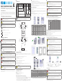 1
1
-
 2
2
-
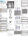 3
3
-
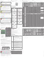 4
4
-
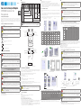 5
5
-
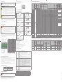 6
6
-
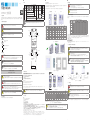 7
7
-
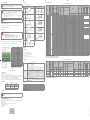 8
8
-
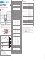 9
9
-
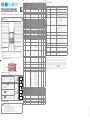 10
10
-
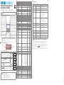 11
11
-
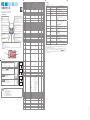 12
12


他の言語で
- español: WEG CFW500 Guía de instalación
- português: WEG CFW500 Guia de instalação
その他のドキュメント
-
GYS COMPASS KIT FOR PLASMA TORCHES MT25K/MT35K/MT45 - ZMT25K/35K- TPT40 - Z データシート
-
Bosch SKS68BB008/01 ユーザーマニュアル
-
Siruba F007K Air Type CE 取扱説明書
-
Delta M100_210 ユーザーマニュアル
-
Philips HD9312/00 Product Datasheet
-
REXON VG1500R 取扱説明書
-
Delta Electronics B07S200 クイックスタートガイド
-
Seiko 7T84 取扱説明書
-
Mitsubishi Electric FR-A800M ユーザーマニュアル
-
Schneider Electric ATS480 软起动器 取扱説明書