
L1
®
Compact
Portable Line Array System
Owner’s Guide
©2009 Bose Corporation, The Mountain,
Framingham, MA 01701-9168 USA
AM325334 Rev.00
www.Bose.com/musicians
L1 Compact Cover_APAC_TCH.fm Page 1 Wednesday, August 26, 2009 2:58 PM

Quick setup guide
Guía rápida de instalación
Notice de montage
Cajun_In-Guide_QSG.fm Page 1 Wednesday, August 26, 2009 1:26 PM
Quick setup guide
Guía rápida de instalación
Notice de montage
Cajun_In-Guide_QSG.fm Page 1 Wednesday, August 26, 2009 1:26 PM
Quick setup guide
Guía rápida de instalación
Notice de montage
Cajun_In-Guide_QSG.fm Page 1 Wednesday, August 26, 2009 1:26 PM
¤Ù‡Á×Í¡ÒõԴµÑé§Í‡ҧÃÇ´àÃçÇ
Guía rápida de instalación
Notice de montage
CajunOG.book Page 1 Tuesday, August 25, 2009 7:55 PM
빠른 설치 안내서
CajunOG_KOR.book Page 1 Tuesday, August 25, 2009 5:10 PM
CajunOG_CHT.book Page 1 Tuesday, August 25, 2009 4:46 PM
ﻊﻳﺮﺴﻟﺍ ﺩﺍﺪﻋﻹﺍ ﻞﻴﻟﺩ
Guía rápida de instalación
Notice de montage
Quick setup guide
Guía rápida de instalación
Notice de montage
Cajun_In-Guide_QSG.fm Page 1 Wednesday, August 26, 2009 1:26 PM

CajunOG.book Page 2 Wednesday, August 26, 2009 2:33 PM

English
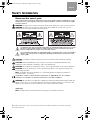
SAFETY INFORMATION
Please read this owner’s guide
Please take the time to follow the instructions in this owner’s guide carefully. It will help you set up
and operate your system properly and enjoy its advanced features. Please save this owner’s guide
for future reference.
WARNING: To reduce the risk of fire or electrical shock, do not expose the system to rain or moisture.
WARNING: To reduce the risk of electric shock, do not disassemble this system unless you are
qualified. Refer servicing to qualified service personnel.
The lightning flash with arrowhead symbol within an equilateral triangle alerts the user to the
presence of uninsulated, dangerous voltage within the system enclosure that may be of
sufficient magnitude to constitute a risk of electrical shock.
The exclamation point within an equilateral triangle, as marked on the system, is intended to
alert the user to the presence of important operating and maintenance instructions in this
owner’s guide.
CAUTION: This product shall be connected to a mains socket outlet with a protective earthing
connection.
CAUTION: Make no modifications to the system or accessories. Unauthorized alterations may
compromise safety, regulatory compliance, and system performance.
CAUTION: Do not place any naked flame sources, such as lighted candles, on or near the apparatus.
CAUTION: Where the mains plug is used as the disconnect device, such disconnect device shall
remain readily operable.
Note: The product must be used indoors. It is neither designed nor tested for use outdoors, in
recreation vehicles, or on boats.
This product conforms to all EU Directive requirements as applicable by law. The complete
Declaration of Conformity can be found at www.Bose.com/static/compliance.
WARNING: Do not expose this apparatus to dripping or splashing and do not place objects filled with
liquids, such as vases, on or near the apparatus As with any electronic products, use care not to spill
liquids into any part of the system. Liquids can cause a failure and/or a fire hazard.
Japan only:
Note: Provide an earth connection before the main plug is connected to the mains.
©2009 Bose Corporation. No part of this work may be reproduced, modified, distributed, or otherwise used without
prior written permission.
CajunOG.book Page 2 Wednesday, August 26, 2009 2:33 PM

TAB English TAB TAB 4, 11 TAB 5, 12 TAB 2, 9, 16 TAB 1, 8, 15
IMPORTANT SAFETY INSTRUCTIONS
1. Read these instructions.
2. Keep these instructions.
3. Heed all warnings.
4. Follow all instructions.
5. Do not use this apparatus near water.
6. Clean only with a dry cloth.
7. Do not block any ventilation openings.
Install in accordance with the manufac-
turer’s instructions.
8. Do not install near any heat sources,
such as radiators, heat registers, stoves,
or other apparatus (including amplifiers)
that produce heat.
9. Do not defeat the safety purpose of the
polarized or grounding-type plug. A
polarized plug has two blades with one
wider than the other. A grounding-type
plug has two blades and a third ground-
ing prong. The wider blade or third prong
is provided for your safety. If the pro-
vided plug does not fit into your outlet,
consult an electrician for replacement of
the obsolete outlet.
10. Protect the power cord from being
walked on or pinched, particularly at
plugs, convenience receptacles, and
the point where they exit from the
apparatus.
11. Only use attachments/accessories
specified by the manufacturer.
12. Use only with the cart, stand,
tripod, bracket, or table speci-
fied by the manufacturer or sold
with the apparatus. When a cart
is used, use caution when moving the
cart/apparatus combination to avoid
injury from tip-over.
13. Unplug this apparatus during lightning
storms or when unused for long periods
of time.
14.
Refer all servicing to qualified service
personnel.
Servicing is required when
the apparatus has been damaged in any
way, such as power-supply cord or plug
is damaged, liquid has been spilled or
objects have fallen into the apparatus,
the apparatus has been exposed to rain
or moisture, does not operate normally,
or has been dropped.
15. To prevent risk of fire or electric shock,
avoid overloading wall outlets, exten-
sion cords, or integral convenience
receptacles.
16. Do not let objects or liquids enter the
product – as they may touch dangerous
voltage points or short-circuit parts that could
result in a fire or electric shock.
17. See product enclosure for safety-related
markings.
18. Use proper power sources – Plug the prod-
uct into a proper power source, as described
in the operating instructions or as marked on
the product.
19. Apparatus shall not be exposed to drip-
ping or splashing, and no objects filled
with liquids, such as vases, shall be
placed on the apparatus.
20. No naked flame source, such as lighted
candles, should be placed on or near the
apparatus.
21. Power LED – Indicates power status.
Blue: Power on.
Information about products that
generate electrical noise
This equipment has been tested and found to
comply with the limits for a Class A digital
device, pursuant to Part 15 of the FCC rules.
These limits are designed to provide
reasonable protection against harmful
interference in a commercial environment. This
equipment generates, uses, and can radiate
radio frequency energy and, if not installed and
used in accordance with the instructions, may
cause harmful interference to radio
communications. Operation of this equipment
in a residential area is likely to cause harmful
interference, in which case the user will be
required to correct the interference at his own
expense.
This product complies with the Canadian
ICES-003 Class A specifications.
CajunOG.book Page 3 Wednesday, August 26, 2009 2:33 PM

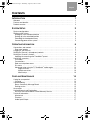
CONTENTS
TAB TAB TAB TAB 4, 11 TAB 3, 10 TAB 2, 9, 16 English
INTRODUCTION 1
Welcome . . . . . . . . . . . . . . . . . . . . . . . . . . . . . . . . . . . . . . . . . . . . . . . . . . . . . . . . . . . . . 1
Features and benefits . . . . . . . . . . . . . . . . . . . . . . . . . . . . . . . . . . . . . . . . . . . . . . . . . . . . 1
Product overview . . . . . . . . . . . . . . . . . . . . . . . . . . . . . . . . . . . . . . . . . . . . . . . . . . . . . . . 2
SYSTEM SETUP 3
System configurations . . . . . . . . . . . . . . . . . . . . . . . . . . . . . . . . . . . . . . . . . . . . . . . . . . . 3
Setting up the system . . . . . . . . . . . . . . . . . . . . . . . . . . . . . . . . . . . . . . . . . . . . . . . . . . . 4
Setting up in the collapsed position . . . . . . . . . . . . . . . . . . . . . . . . . . . . . . . . . . . . . . . 4
Setting up in the extended position . . . . . . . . . . . . . . . . . . . . . . . . . . . . . . . . . . . . . . . 4
Extending the Loudspeaker Array . . . . . . . . . . . . . . . . . . . . . . . . . . . . . . . . . . . . . . . . 5
Connecting power to the system . . . . . . . . . . . . . . . . . . . . . . . . . . . . . . . . . . . . . . . . . 5
OPERATING INFORMATION 6
Connections and controls . . . . . . . . . . . . . . . . . . . . . . . . . . . . . . . . . . . . . . . . . . . . . . . . 6
Rear panel outputs . . . . . . . . . . . . . . . . . . . . . . . . . . . . . . . . . . . . . . . . . . . . . . . . . . . . 7
Plugging in your sources . . . . . . . . . . . . . . . . . . . . . . . . . . . . . . . . . . . . . . . . . . . . . . . . . 7
Setting the Channel 1 (microphone) controls . . . . . . . . . . . . . . . . . . . . . . . . . . . . . . . . . . 8
Setting the Channel 2 controls . . . . . . . . . . . . . . . . . . . . . . . . . . . . . . . . . . . . . . . . . . . . . 8
Applying the acoustic guitar ToneMatch
®
preset . . . . . . . . . . . . . . . . . . . . . . . . . . . . . 9
Connection scenarios . . . . . . . . . . . . . . . . . . . . . . . . . . . . . . . . . . . . . . . . . . . . . . . . . . . . 9
Classroom . . . . . . . . . . . . . . . . . . . . . . . . . . . . . . . . . . . . . . . . . . . . . . . . . . . . . . . . . . . 9
Presentations . . . . . . . . . . . . . . . . . . . . . . . . . . . . . . . . . . . . . . . . . . . . . . . . . . . . . . . . 10
Solo musical performances . . . . . . . . . . . . . . . . . . . . . . . . . . . . . . . . . . . . . . . . . . . . . 11
DJ events . . . . . . . . . . . . . . . . . . . . . . . . . . . . . . . . . . . . . . . . . . . . . . . . . . . . . . . . . . . 11
Advanced setup using the T1 ToneMatch
®
audio engine . . . . . . . . . . . . . . . . . . . . . . . 12
Single musician . . . . . . . . . . . . . . . . . . . . . . . . . . . . . . . . . . . . . . . . . . . . . . . . . . . 12
Multiple musicians . . . . . . . . . . . . . . . . . . . . . . . . . . . . . . . . . . . . . . . . . . . . . . . . . 13
Mixed setup . . . . . . . . . . . . . . . . . . . . . . . . . . . . . . . . . . . . . . . . . . . . . . . . . . . . . . 13
CARE AND MAINTENANCE 14
Caring for your product . . . . . . . . . . . . . . . . . . . . . . . . . . . . . . . . . . . . . . . . . . . . . . . . . . 14
Cleaning . . . . . . . . . . . . . . . . . . . . . . . . . . . . . . . . . . . . . . . . . . . . . . . . . . . . . . . . . . . . 14
Troubleshooting . . . . . . . . . . . . . . . . . . . . . . . . . . . . . . . . . . . . . . . . . . . . . . . . . . . . . . . . 14
Bose
®
Community Message Board . . . . . . . . . . . . . . . . . . . . . . . . . . . . . . . . . . . . . . . 15
Getting service . . . . . . . . . . . . . . . . . . . . . . . . . . . . . . . . . . . . . . . . . . . . . . . . . . . . . . . 15
Accessories . . . . . . . . . . . . . . . . . . . . . . . . . . . . . . . . . . . . . . . . . . . . . . . . . . . . . . . . . . . 15
Limited Warranty and Registration . . . . . . . . . . . . . . . . . . . . . . . . . . . . . . . . . . . . . . . . . . 16
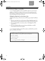
What you must do to obtain Limited Warranty Service: . . . . . . . . . . . . . . . . . . . . . . . . 16
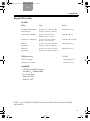
Technical Information . . . . . . . . . . . . . . . . . . . . . . . . . . . . . . . . . . . . . . . . . . . . . . . . . . . . 17
Mechanical . . . . . . . . . . . . . . . . . . . . . . . . . . . . . . . . . . . . . . . . . . . . . . . . . . . . . . . . . . 17
Electrical . . . . . . . . . . . . . . . . . . . . . . . . . . . . . . . . . . . . . . . . . . . . . . . . . . . . . . . . . . . . 17
Audio Input/Output . . . . . . . . . . . . . . . . . . . . . . . . . . . . . . . . . . . . . . . . . . . . . . . . . . . . 17
CajunOG.book Page ii Wednesday, August 26, 2009 2:33 PM

1
TAB English TAB TAB 4, 11 TAB 5, 12 TAB 2, 9, 16 TAB 1, 8, 15
INTRODUCTION
Welcome
Thank you for purchasing the Bose
®
L1
®
Compact Portable Line Array System.
Whether you are a musician amplifying your instruments, a mobile DJ
entertaining an audience, or the host of your own special event, this system
will provide quality sound for audiences of approximately 100 people.
This owner’s guide provides detailed setup and operating instructions for
your L1
®
Compact system and explains how to connect to a variety of
audio sources. For additional information on using this system, including
tips, techniques, and frequently asked questions, please visit
www.Bose.com/musicians on the Internet.
Features and benefits
• Carry it in one trip – The entire system is light enough to be carried in a single
trip.
• Set it up in one minute – The interlocking components of the L1
®
Compact
system allow system setup in less than a minute. There are no external
speaker wires required. An integrated bass enclosure with an intuitive user
interface eliminates the need for separate components.
• Fill the room with one system – Whether you’re performing live or playing
back prerecorded music, whether you’re performing in a coffeehouse or a
100-seat room, Bose
®
Spatial Dispersion™ loudspeaker technology provides
nearly 180º of tonally balanced sound coverage so there are no dead spots.
• PA and monitor combined – Audience members enjoy a more consistent and
intimate listening experience because the system sets up behind the
performer and serves as both the monitor for the stage and amplification
system for the audience. The performer alone controls the sound.
• Versatility – In addition to musical performances, the L1
®
Compact provides
quality sound for a wide variety of general-purpose uses including
presentations, celebrations, speeches, and music playback for about
100 people.
• Integrated ToneMatch
®
signal processing – Provides a high level of tone
customization on your microphone or instrument to provide a listening
experience that most musicians only achieve using a recording studio.
• Two setup options – The L1
®
Compact system can be used in either the
collapsed position for smaller audiences or extended positions for larger
audiences.
CajunOG.book Page 1 Wednesday, August 26, 2009 2:33 PM

2
INTRODUCTION
TAB TAB TAB TAB 4, 11 TAB 3, 10 TAB 2, 9, 16
English
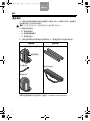
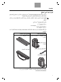
Product overview
The L1
®
Compact Portable Line Array System is shipped in two cartons.
Carefully unpack the cartons and check that you have all the items listed on this
page.
WARNING: To avoid danger of suffocation, keep the plastic bags out of the reach
of children.
The L1
®
Compact system consists of:
•L1
®
Compact Power Stand
•L1
®
Compact Loudspeaker Array
•L1
®
Compact Extensions
The L1
®
Compact system comes with a slipcover for the Power Stand and a
padded carry bag for the L1
®
Compact Extensions.
For a complete list of optional equipment and accessories, please visit:
www.Bose.com/musicians.
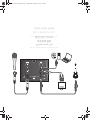
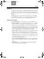
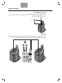
Power stand carton Extensions carton
L1
®
Compact Power Stand
with Loudspeaker Array
AC power cord
Power Stand slipcover
L1
®
Compact Extensions
Extensions carry bag
Loudspeaker
Array
CajunOG.book Page 2 Wednesday, August 26, 2009 2:33 PM

3
TAB English TAB TAB 4, 11 TAB 5, 12 TAB 2, 9, 16 TAB 1, 8, 15
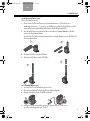
SYSTEM SETUP
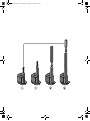
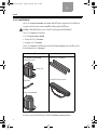
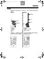
System configurations
You can set up the versatile L1
®
Compact system in two unique positions.
The examples below will help you quickly identify the position that can work
best for you.
The L1
®
Compact Extensions are not required when using the L1
®
Compact
Portable Line Array System in the collapsed position. They are included for
situations where you need to elevate the Loudspeaker Array to project sound
to larger audiences.
Smaller audiences
• Intimate acoustic performances
• Music playback
• Presentations
•Speeches
Larger audiences
•Musical performances
–
auditorium/coffeehouse
• DJ events
• Announcements
– larger spaces
Collapsed position
Loudspeaker
Power
Extended position
Power Stand
Array
Extension
Extension
Stand
Tabletop
Array
Loudspeaker
CajunOG.book Page 3 Wednesday, August 26, 2009 2:33 PM

SYSTEM SETUP
4
TAB TAB TAB TAB 4, 11 TAB 3, 10 TAB 2, 9, 16
English
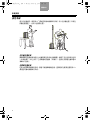
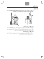
Setting up the system
Before making any connections, you should set the L1
®
Compact Portable Line
Array System up either in the collapsed position (the system is shipped in the
collapsed position) or the extended position.
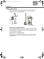
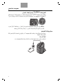
Setting up in the collapsed position
To get the most sound quality and ensure that seated audience members enjoy the
full frequency range of the system, position it on a table (shown above) at ear-level
or at the front edge of a stage (not shown). This will allow sound to project clearly
and evenly throughout the audience.
Setting up in the extended position
In larger rooms, or with larger audiences where the sound could be blocked by
obstacles, it is best to set up the L1
®
Compact Portable Line Array System in the
extended position.
CajunOG.book Page 4 Wednesday, August 26, 2009 2:33 PM

5
SYSTEM SETUP
TAB English TAB TAB 4, 11 TAB 5, 12 TAB 2, 9, 16 TAB 1, 8, 15
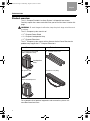
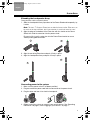
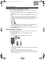
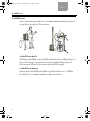
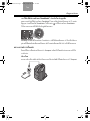
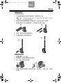
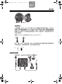
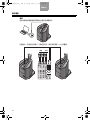
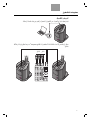
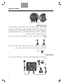
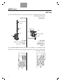
Extending the Loudspeaker Array
Once you have set the system in place:
1. Slide the Loudspeaker Array up and out of the Power Stand and temporarily lay
it aside.
Note: The two L1
®
Compact Extensions are identical to each other. Either one can
be used on the top or bottom, but if one extension is used, both must be used.
2. Align the plug on the bottom of the Extension with the socket on the Power
Stand, then slide the extension into the power stand.
Be sure to fully insert the extension into the Power Stand socket to assure
stability and a good connection.
3. Align the remaining Extension and push it firmly in place.
4. Align the Loudspeaker Array and push it firmly in place.
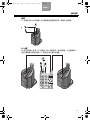
Connecting power to the system
1. Make sure the power switch is off (down position).
2. Plug one end of the power cord into the connector on the power stand.
3. Plug the other end into a live electrical receptacle.
4. Before turning the system on, connect your sound sources. See “Operating
Information” on page 6, and “Plugging in your sources” on page 7.
1
2
3
4
1
2
3
CajunOG.book Page 5 Wednesday, August 26, 2009 2:33 PM

6
TAB TAB TAB TAB 4, 11 TAB 3, 10 TAB 2, 9, 16
English
OPERATING INFORMATION
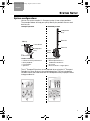
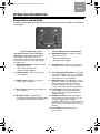
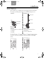
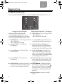
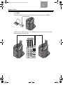
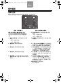
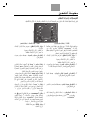
Connections and controls
The power stand control panel provides all the necessary connectors, controls, and indicators
for operation.
1
2
3
4
5
6
7
8
9
10
11
12
Channel 1 (Microphone input) Channel 2 (Utility channel – multiple input)
The channel 1 input is for use only with a
microphone. Integrated ToneMatch
®
signal
processing provides a high level of tone
customization to provide a listening experience
that most musicians can only achieve using a
recording studio.
6. Signal/Clip indicator – Displays the input
signal status in color.
• Green: Input signal present
• Red: Input signal clipping
1. Signal/Clip indicator – Displays the input
signal status in color.
• Green: Input signal present
• Red: Input signal clipping
7. Volume control – Adjusts the overall volume
of all input sources connected to Channel 2.
2. Volume control – Adjusts the volume of
your microphone.
8.
⅛-inch (3.5 mm) stereo input – Analog input
for connecting audio sources such as portable
mp3 players, satellite radio, laptop computers,
video projectors, and smart boards.
3. Treble control – Adjusts the amount of
treble on your microphone.
9. RCA stereo input – Analog input for connect-
ing audio sources such as DVD players, VCR
players, video game consoles, DJ mixers,
Keyboards and other instruments. For best
results, connect both the left and right signals.
4. Bass control – Adjusts the amount bass on
your microphone.
10. ¼-inch input – Balanced analog input for
connecting guitars and other instruments.
Accepts either ¼-inch TRS balanced or TS
unbalanced cables.
5. Microphone input – Analog input for
connecting a balanced XLR microphone cable.
A ToneMatch
®
microphone preset is built in.
11. ToneMatch
®
switch – When connecting an
acoustic guitar to the ¼-inch input, move the
switch to the position to enable a
ToneMatch
®
preset. When connecting anything
other than an acoustic guitar to the ¼-inch
input, move the switch down to the Line Level
position.
12. Power LED – Indicates power status.
Blue: Power on
CajunOG.book Page 6 Wednesday, August 26, 2009 2:33 PM

7
OPERATING INFORMATION
TAB English TAB TAB 4, 11 TAB 5, 12 TAB 2, 9, 16 TAB 1, 8, 15
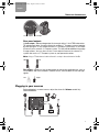
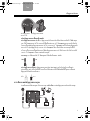
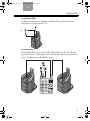
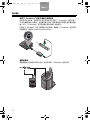
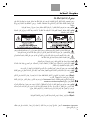
Rear panel outputs
¼-inch output – Mono analog output that accepts either ¼ inch TRS balanced or
TS unbalanced cables. Can be used to link multiple L1
®
Compact systems together
by connecting the ¼-inch output from one L1
®
Compact system to the ¼-inch input
(Channel 2) on a second L1
®
Compact system. This will provide additional coverage
in larger spaces. You can also use the ¼-inch output to connect to a house PA
system and use the L1
®
Compact system as your personal monitor.
Note: Using a TS unbalanced cable will result in a drop in the audio level of -6dBu.
RCA output
– Mono line level analog output for connecting audio devices such as
CD recorders and flash recorders. For best results, connect both the left and right
signals.
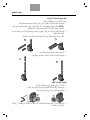
Plugging in your sources
Before plugging in a sound source, adjust the channel’s Volume control fully
counterclockwise.
¼-inch output RCA output
TRS TS
Left Right
CajunOG.book Page 7 Wednesday, August 26, 2009 2:33 PM

8
OPERATING INFORMATION
TAB TAB TAB TAB 4, 11 TAB 3, 10 TAB 2, 9, 16
English
Setting the Channel 1 (microphone) controls
Channel 1 is only intended for use with a dynamic handheld microphone. Do not
connect any other sources to this input.
1. Before using the microphone, adjust the Channel 1 Volume control fully counter-
clockwise.
2. While speaking into the microphone, adjust the Volume control to the desired
level.
For best results, keep the microphone close to your lips when speaking.
Holding the microphone more than 3 inches (7.6 cm) away from your lips when
speaking will lead to less overall volume and may impact overall clarity.
The Channel 1 Microphone Input is equipped with an integrated ToneMatch
®
preset to automatically optimize the sound of your microphone.
3. Adjust the Treble and Bass controls to make further refinements based on your
personal preference.
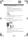
Setting the Channel 2 controls
When connecting an audio source to any of the Channel 2 inputs, follow these
steps to adjust the volume.
1. On the power stand, adjust the Channel 2 Volume control fully
counterclockwise.
2. Connect the audio source to the appropriate Channel 2 input.
3. Turn the Channel 2 Volume control clockwise until the volume indicator glows
green or yellow.
If the volume indicator steadily glows red, decrease the volume.
Note: You can connect multiple audio sources, one to each of the Channel 2 Inputs,
at the same time. However, you must then adjust the volume on each source device to
achieve the mix you desire.
CajunOG.book Page 8 Wednesday, August 26, 2009 2:33 PM

9
OPERATING INFORMATION
TAB English TAB TAB 4, 11 TAB 5, 12 TAB 2, 9, 16 TAB 1, 8, 15
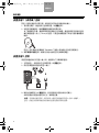
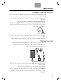
Applying the acoustic guitar ToneMatch
®
preset
You can access the ToneMatch
®
preset by plugging into the ¼-inch input on
Channel 2 and moving the ToneMatch
®
switch to the position. The ToneMatch
®
preset is designed specifically for use with an acoustic guitar.
Note: The ToneMatch
®
preset switch only affects the ¼-inch input. Sound from devices
connected to the ⅛-inch stereo input and the RCA stereo input are not affected.
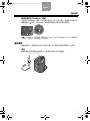
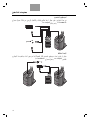
Connection scenarios
There are many ways to connect and use the L1
®
Compact system. The following
pages show a few examples of typical scenarios.
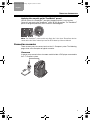
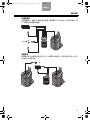
Classroom
A typical setup scenario for a classroom could include a DVD player connected to
the L1
®
Compact system.
CajunOG.book Page 9 Wednesday, August 26, 2009 2:33 PM

10
OPERATING INFORMATION
TAB TAB TAB TAB 4, 11 TAB 3, 10 TAB 2, 9, 16
English
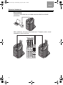
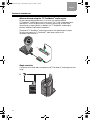
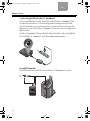
Presentations
Connect the audio output from your laptop computer and deliver multimedia
presentations.
Within auditoriums, the setup could include two L1
®
Compact systems, several
microphones, and a small mixer.
Wireless
Wired
CajunOG.book Page 10 Wednesday, August 26, 2009 2:33 PM

11
OPERATING INFORMATION
TAB English TAB TAB 4, 11 TAB 5, 12 TAB 2, 9, 16 TAB 1, 8, 15
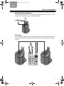
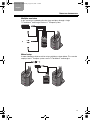
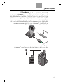
Solo musical performances
The multiple inputs on the L1
®
Compact system allow a soloist to connect a vocal
microphone, musical instrument, and backing tracks.
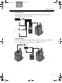
DJ events
DJs use multiple input sources (CD player, MP3 player, etc.) plugged into a mixer. In
this scenario, two mixer outputs are fed into two L1
®
Compact systems for stereo
sound.
CajunOG.book Page 11 Wednesday, August 26, 2009 2:33 PM

12
OPERATING INFORMATION
TAB TAB TAB TAB 4, 11 TAB 3, 10 TAB 2, 9, 16
English
Advanced setup using the T1 ToneMatch
®
audio engine
For more demanding performances, a musician can add the optional
T1 ToneMatch
®
audio engine to his or her setup. The T1 offers expanded inputs
and outputs, access to quality effects, dynamics processing, and our most
advanced tone-shaping library. In addition, the T1 ToneMatch
®
audio engine
provides additional input/output capabilities.
The optional T1 ToneMatch
®
audio engine requires the optional power supply.
To learn more about the T1 ToneMatch
®
audio engine, please visit
www.Bose.com/musicians.
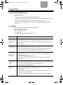
Single musician
A single musician could add a microphone and T1 ToneMatch
®
audio engine to their
setup.
CajunOG.book Page 12 Wednesday, August 26, 2009 2:33 PM

13
OPERATING INFORMATION
TAB English TAB TAB 4, 11 TAB 5, 12 TAB 2, 9, 16 TAB 1, 8, 15
Multiple musicians
In this scenario, a keyboard-guitar duo sings and plays through a single
T1 ToneMatch
®
audio engine and an L1
®
Compact system.
Mixed setup
A more elaborate multiple musician setup could be as shown below. This scenario
employs two L1
®
Compact systems and a T1 ToneMatch
®
audio engine.
CajunOG.book Page 13 Wednesday, August 26, 2009 2:33 PM

14
TAB TAB TAB TAB 4, 11 TAB 3, 10 TAB 2, 9, 16
English
CARE AND MAINTENANCE
Caring for your product
Cleaning
• Clean the product enclosures using only a soft, dry cloth.
• Do not use any solvents, chemicals, or cleaning solutions containing alcohol,
ammonia, or abrasives.
• Do not use any sprays near the product or allow liquids to spill into any openings.
• If necessary, you may carefully vacuum the grille of the L1
®
Compact Power
Stand.
Troubleshooting
If you experience problems while using this product, try the following solutions.
Recommended troubleshooting tools
• Spare AC power cord
• XLR and ¼-inch phone plug cables
Problem What to do
System is plugged
in, power switch is
on, but power LED
is off
• Make sure you are using the included L1
®
Compact Power Stand power cable.
• Make sure the power cable is fully engaged into both the Power Stand and the AC outlet.
• Make sure you have power at the AC outlet. Try operating a lamp or other equipment
from the same AC outlet.
• Try a different power cable.
• If available, try a different Power Stand.
Power LED is on,
but no sound
• Make sure the Volume control is turned up on the Power Stand.
• Make sure the volume control is turned up on your instrument.
• Make sure your instrument or audio source is plugged into the appropriate input jack.
• Connect your instrument or audio source to the Power Stand using a different cable.
Middle to high
frequencies absent
from the L1
®
Compact
Loudspeaker Array
• When in the collapsed position, always place the system on a tabletop so it is level with
the listeners’ ears.
• Make sure the L1
®
Compact Extensions and L1
®
Compact Loudspeaker Array are firmly
seated in their connectors.
• Make sure connections are not bent or broken.
• Try cleaning the contacts on the loudspeaker top and bottom with electronic contact
spray cleaner.
Instrument or audio
source sounds
distorted
• Lower the volume of the connected audio source.
• If you are connecting an external mixer, make sure the equalization controls for low, mid,
and high on the mixer are set to mid position.
• Reduce the output of the mixer.
Microphone is
encountering
feedback
• Position the microphone so it is not pointing directly at its respective L1
®
Compact
Loudspeaker array.
• Try positioning the microphone so it nearly touches your lips.
• Try a different microphone.
• Try a different position for the L1
®
Compact Portable Line Array System and/or vocalist
on stage.
• Increase the distance from the loudspeaker to the microphone.
• If using a vocal effects processor, make sure it is not contributing to the feedback.
CajunOG.book Page 14 Wednesday, August 26, 2009 2:33 PM
ページが読み込まれています...
ページが読み込まれています...
ページが読み込まれています...
ページが読み込まれています...
ページが読み込まれています...
ページが読み込まれています...
ページが読み込まれています...
ページが読み込まれています...
ページが読み込まれています...
ページが読み込まれています...
ページが読み込まれています...
ページが読み込まれています...
ページが読み込まれています...
ページが読み込まれています...
ページが読み込まれています...
ページが読み込まれています...
ページが読み込まれています...
ページが読み込まれています...
ページが読み込まれています...
ページが読み込まれています...
ページが読み込まれています...
ページが読み込まれています...
ページが読み込まれています...
ページが読み込まれています...
ページが読み込まれています...
ページが読み込まれています...
ページが読み込まれています...
ページが読み込まれています...
ページが読み込まれています...
ページが読み込まれています...
ページが読み込まれています...
ページが読み込まれています...
ページが読み込まれています...
ページが読み込まれています...
ページが読み込まれています...
ページが読み込まれています...
ページが読み込まれています...
ページが読み込まれています...
ページが読み込まれています...
ページが読み込まれています...
ページが読み込まれています...
ページが読み込まれています...
ページが読み込まれています...
ページが読み込まれています...
ページが読み込まれています...
ページが読み込まれています...
ページが読み込まれています...
ページが読み込まれています...
ページが読み込まれています...
ページが読み込まれています...
ページが読み込まれています...
ページが読み込まれています...
ページが読み込まれています...
ページが読み込まれています...
ページが読み込まれています...
ページが読み込まれています...
ページが読み込まれています...
ページが読み込まれています...
ページが読み込まれています...
ページが読み込まれています...
ページが読み込まれています...
ページが読み込まれています...
ページが読み込まれています...
ページが読み込まれています...
-
 1
1
-
 2
2
-
 3
3
-
 4
4
-
 5
5
-
 6
6
-
 7
7
-
 8
8
-
 9
9
-
 10
10
-
 11
11
-
 12
12
-
 13
13
-
 14
14
-
 15
15
-
 16
16
-
 17
17
-
 18
18
-
 19
19
-
 20
20
-
 21
21
-
 22
22
-
 23
23
-
 24
24
-
 25
25
-
 26
26
-
 27
27
-
 28
28
-
 29
29
-
 30
30
-
 31
31
-
 32
32
-
 33
33
-
 34
34
-
 35
35
-
 36
36
-
 37
37
-
 38
38
-
 39
39
-
 40
40
-
 41
41
-
 42
42
-
 43
43
-
 44
44
-
 45
45
-
 46
46
-
 47
47
-
 48
48
-
 49
49
-
 50
50
-
 51
51
-
 52
52
-
 53
53
-
 54
54
-
 55
55
-
 56
56
-
 57
57
-
 58
58
-
 59
59
-
 60
60
-
 61
61
-
 62
62
-
 63
63
-
 64
64
-
 65
65
-
 66
66
-
 67
67
-
 68
68
-
 69
69
-
 70
70
-
 71
71
-
 72
72
-
 73
73
-
 74
74
-
 75
75
-
 76
76
-
 77
77
-
 78
78
-
 79
79
-
 80
80
-
 81
81
-
 82
82
-
 83
83
-
 84
84


