
– 1 –
Quick Start Guide
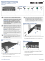
Attach the Brackets
1. Attach each of the front- and rear-post brackets to the switch
using four of the included bracket screws.
2. Use the screws and cage/clip nuts supplied with the rack to
secure the switch in the rack.
Adjust Rear-Post Bracket Ears
1. Lock the position of the rear-post bracket ears using the included
position-locking screws.
You can adjust the rear-post bracket ears to fit different rack
depths from 56 cm to 75 cm.
Ground the Switch
1. Ensure the rack is properly grounded and in compliance with
ETSI ETS 300 253. Verify that there is a good electrical
connection to the grounding point on the rack (no paint or
isolating surface treatment).
2. Attach the grounding wire (#14 AWG) to the grounding point
on the switch rear panel. Then connect the other end of the wire
to rack ground.
Warning:
For a safe and reliable installation, use only
the accessories and screws provided with the AS5835-
54T. Use of other accessories and screws could result in
damage to the unit. Any damages incurred by using
unapproved accessories are not covered by the warranty.
Avertissement:
Pour une installation sûre et fiable,
utilisez uniquement les accessoires et les vis fournies avec
le AS5835-54T. L’utilisation d’autres accessoires et vis
pourrait endommager l’appareil. Les dommages causés
par l’utilisation d’accessoires non approuvés ne sont pas
couverts par la garantie.
Caution:
The switch includes plug-in power supply (PSU)
and fan tray modules that are installed into its chassis. All
installed modules must have a matching airflow direction.
That is, if the installed power modules have a front-to-back
(F2B) airflow direction, all the installed fan tray modules
must also have a F2B airflow direction.
Attention:
Le commutateur comprend des modules
d’alimentation et de bac de ventilateurs installés sur son
châssis. Tous les modules installés doivent avoir une
direction de circulation d’air correspondante. C’est-à-dire
que tous les modules doivent avoir la même direction de
circulation d’air : avant vers arrière (F2B), ou arrière vers
avant (B2F).
Note:
The switch has the Open Network Install
Environment (ONIE) software installer pre-loaded on the
switch, but no switch software image. Information about
compatible switch software can be found at
www.edge-core.com.
1
1
1
2
Caution:
Installing the switch in a rack requires two
people. One person should position the switch in the rack,
while the other person secures it using the rack screws.
Attention:
Deux personnes sont nécessaires pour installer
un commutateur dans un bâti : La première personne va
positionner le commutateur dans le bâti, la seconde va le
fixer avec des vis de montage.
2
1
3
1
2
E092019-CS-R01
150200002099A
www.edge-core.com
54-Port 10G/100G Ethernet Switch
AS5835-54T
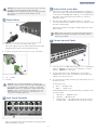
1.
54-Port 10G/100G Ethernet Switch
AS5835-54T
2. Rack mounting kit—2 front-post brackets, 2 rear-post
brackets, 20 screws, and 2 ear-locking screws
3. Power cord (included with AC PSUs only)
4. Ground wire (included with DC PSUs only)
5. Console cable—RJ-45 to D-Sub
6. DC power connector (included with 48 VDC PSU only)
7. Documentation—Quick Start Guide (this document) and
Safety and Regulatory Information
1
Package Contents
2
3
4
5
7
6

Quick Start Guide
– 2 –
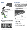
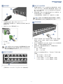
Connect Power
1. Install one or two AC or DC PSUs in the switch.
The switch supports up to two PSUs that must have the same
matching airflow direction as the installed fan tray.
2. Connect an external AC or DC power source to the PSUs.
1. DC Return
2.
-36 – -75 VDC
3. Ground
Verify Switch Operation
1. Verify basic switch operation by checking the system LEDs.
When operating normally, the PSU1/PSU2, OS Diag, and Fan
LEDs should all be on green.
Perform Initial System Boot
1. If the network operating system (NOS) installer is located on a
network server, first connect the RJ-45 Management (Mgmt) port
to the network using 100-ohm Category 5, 5e or better twisted-
pair cable. (Not required if the NOS installer is located on
attached storage.)
2. Boot the switch. Wait for the ONIE software to locate and
execute the NOS installer, and then wait for the installer to load
the NOS software image.
Subsequent switch boots will bypass ONIE and directly run the
NOS software.
Connect Network Cables
1. For RJ-45 ports, use 100-ohm Category 6, 6a, or 7 twisted-pair
cable for 10GBASE-T connections, or Category 5e or better
cable for 1000BASE-T connections.
2. Connect DAC cables to the QSFP28 slots. Or first install
QSFP28 transceivers in the slots and then connect fiber optic
cabling to the transceiver ports.
3. As connections are made, check the port status LEDs to be sure
the links are valid.
For the RJ-45 ports:
■
Green — 10 Gbps mode
■
Amber — 1 Gbps mode
Each QSFP28 port has four LEDs that indicate valid links in the
following modes:
■
1 LED Green — 100 Gbps mode
■
1 LED Blue — 40 Gbps mode
■
1-4 LEDs Amber — 25 Gbps breakout mode (four lanes)
■
1-4 LEDs Purple — 10 Gbps breakout mode (four lanes)
Caution:
The earth connection must not be removed unless
all supply connections have been disconnected.
Attention:
Le raccordement à la terre ne doit pas être retiré
sauf si toutes les connexions d’alimentation ont été
débranchées.
Caution:
Use a UL/IEC/EN 60950-1 certified power
supply to connect to a DC converter, and a #14 AWG wire
(for -36 VDC to -75 VDC PSU) to connect to a DC PSU.
Attention:
Utilisez une alimentation certifiée UL/IEC/EN
60950-1 pour le connecter à un convertisseur CC et un
câble AWG #14 (pour -36 VDC à -75 VDC) pour vous
connecter à une alimentation CC.
4
2
1
2
1
3
5
1
Note:
Refer to the network operating system (NOS) installer
and NOS documentation for details on software options
and set up for ONIE.
6
7
1
2
3

Quick Start Guide
– 3 –
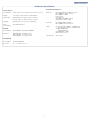
Switch Chassis
Size (WxDxH) 442.5 x 473.3 x 43.95 mm (17.42 x 18.63 x 1.73 in)
Weight 9.59 kg (21.14 lb), with two installed PSUs
Temperature Operating: 0° C to 40° C (32° F to 104° F)
Storage: -40° C to 70° C (-40° F to 158° F)
Humidity Operating: 5% to 95% (non-condensing)
Power
Consumption
323 Watts maximum
AC PSU
Power Rating 100–240 VAC, 50–60 Hz, 400 Watts
AC Input 100-240 VAC, 50-60 Hz, 6–3 A
100–127 VAC, 47–63 Hz, 6.0 A
200–240 VAC, 47–63 Hz, 3.0 A
48 VDC PSU
Power Rating 48 VDC, 400 Watts
DC Input -36 – -75 VDC, 14–7 A
Regulatory Compliances
Emissions EN 55032:2015+AC:2016, Class A
EN 61000-3-2:2014, Class A
EN 61000-3-3:2013
FCC Class A
VCCI Class A
CCC GB 9254-2008, Class A
BSMI Class A, CNS 13438
Immunity EN 55024:2010+A1:2015
IEC 61000-4-2/3/4/5/6/8/11
Safety UL (CSA 22.2 No 60950-1 & UL60950-1)
(CSA 22.2 No 62368-1 & UL62368-1)
CB (IEC/EN60950-1)
(IEC/EN62368-1)
CCC GB4943.1-2011
BSMI, CNS 14336-1
Taiwan RoHS CNS 15663
Hardware Specifications

– 1 –
快速入门指南
安装支架
1. 使用四个随附的支架螺丝将各个前柱和后柱支架安装到交换
机。
2. 使用机架附带的螺丝和笼具 / 夹子螺母将交换机固定在机架
中。
调整后柱支架吊耳
1. 使用随附的定位螺丝固定后柱支架吊耳的位置。
您可以调节后柱支架吊耳以适合 56 cm 到 75 cm 的不同机架
深度。
将交换机接地
1. 确保机架已正确接地并符合 ETSI ETS 300 253 规范。确认到机
架上接地点的电力连接良好 (未经过油漆或绝缘表面处
理)。
2. 将接地线 (#14 AWG) 连接到交换机后面板上的接地点。然后
将的另一端连接到机架接地端。
警告: 为了可以更安全的使用与安装机台,请务必使用
AS5835-54T 随货附赠的配件,避免导致设备损坏或其他风
险产生。使用未经批准的配件造成的任何损坏,均不在保修
范围内。
小心:
本交换机的机箱中安装有插入式电源 (PSU) 和风
扇架模块。所有已安装模块都要求合适的气流方向。
即,如果安装的电源模块有从前到后 (F2B) 的气流通过,
则所有安装的风扇架模块也必须有 F2B 气流通过。
注意:
本交换机上已预装了 Open Network Install
Environment (ONIE) 软件安装程序,但没有交换机软件映
像。在以下网站可以找到有关兼容交换机软件的信息:
www.edge-core.com。
小心:
将此交换机安装在机架中时需要两个人。一个人
应在机架中托住交换机,另一个人使用机架螺丝固定
它。
1
1
1
2
小心:
必须在所有电源连接都断开的情况下才能移除接
地连接。
2
1
3
1
2
E092019-CS-R01
150200002099A
www.edge-core.com
1.
54
端口
10G/100G
以太网交换机
AS5835-54T
2. 机架安装套件 — 2 个前柱支架, 2 个后柱支架, 20 个螺丝
和 2 个吊耳螺丝。
3. 电源线 (仅随交流电源附带)
4. 接地线 (仅随直流电源附带)
5. 控制台线缆 —RJ-45 转 D-Sub
6. DC 电源转接头 (仅随 48 VDC 电源附带)
7. 文档 —
快速入门指南
(本文档)以及
安全和管制信息
54 端口 10G/100G 以太网交换机
AS5835-54T
1
2 7
5
3
4
6
包装清单

快速入门指南
– 2 –
连接电源
1. 将一个或两个 AC 或 DC PSU 安装在交换机中。
此交换机最多支持 2 个 PSU,并且它们的气流方向必须与所
安装的风扇架相符。
2. 将外部 AC 或 DC 电源连接到 PSU。
1. DC 回返
2.
-36 – -75 VDC
3. 接地
检查交换机运行
1. 通过系统 LED 检查交换机的基本运行。
若运行正常, PSU1/PSU2、 Diag 和 Fan 等 LED 都应显示绿
色。
执行初次系统启动
1. 如果网络操作系统 (NOS) 安装程序位于网络服务器中,应首
先使用 100 欧姆的 5、 5e 类或以上双绞线将 RJ-45 管理
(Mgmt) 端口连接到网络。(NOS 安装程序位于相连的存储装
置中时不需要。)
2. 启动交换机。等待 ONIE 软件找到和执行 NOS 安装程序,然
后等待安装程序加载 NOS 软件映像。
以后交换机启动时将跳过 ONIE 而直接运行 NOS 软件。
连接网线
1. 对于 RJ-45 端口,使用 100 ohm 6、 6a 或 7 类双绞线进行
10GBase-T 连接,或使用 5e 类或更好线缆进行 1000Base-T 连
接。
2. 将 DAC 线连接到 QSFP28 插槽。或者先在插槽中安装 QSFP28
收发器,然后将光纤电缆连接到收发器端口。
3. 建立连接后,检查端口状态 LED,确保连接正常。
RJ-45 端口:
■
绿色 — 10 Gbps 模式
■
琥珀色 — 1 Gbps 模式
每个 QSFP28 端口有四个 LED,在以下模式中指示正常连接 :
■
1 LED 绿色 — 100 Gbps 模式
■
1 LED 蓝色 — 40 Gbps 模式
■
1-4 LED 琥珀色 — 25 Gbps 突破模式 (四通道)
■
1-4 LED 紫色 — 10 Gbps 突破模式 (四通道)
小心:
使用 UL/IEC/EN 60950-1 认证电源线连接到 DC 转
换器,使用 #14 AWG 线(用于 -36 VDC 到 -75 VDC PSU)
连接到 DC PSU。
4
2
1
3
2
1
5
1
注意:
请参考网络操作系统 (NOS) 安装程序和 NOS 文档
以详细了解软件选项和如何设置 ONIE。
6
7
2
1
3

快速入门指南
– 3 –
交换机机箱
尺寸 (WxDxH) 442.5 x 473.3 x 43.95 mm (17.42 x 18.63 x 1.73 英
寸)
重量 9.59 kg (21.14 磅),安装有两个 PSU
温度 工作时:0° C 到 40° C (32° F 到 104° F)
存放时:-40° C 到 70° C (-40° F 到 158° F)
湿度 工作时:5% 到 95% (无冷凝)
功耗 最大 323 W
AC PSU
电源额定值 100–240 VAC, 50-60 Hz, 400 W
交流输入 100-240 V 交流, 50-60 Hz, 6-3 A
100-127 V 交流, 47-63 Hz, 3.0 A
200-240 V 交流, 47–63 Hz, 3.0 A
48 VDC PSU
电源额定值 48 VDC, 400 W
直流输入 -36 – -75 VDC, 14–7 A
管制符合性
辐射
EN 55032:2015+AC:2016, Class A
EN 61000-3-2:2014, Class A
EN 61000-3-3:2013
FCC Class A
VCCI Class A
CCC GB 9254-2008, Class A
BSMI Class A, CNS 13438
抗干扰性
EN 55024:2010+A1:2015
IEC 61000-4-2/3/4/5/6/8/11
安全
UL (CSA 22.2 No 60950-1 & UL60950-1)
(CSA 22.2 No 62368-1 & UL62368-1)
CB (IEC/EN60950-1)
(IEC/EN62368-1)
CCC GB4943.1-2011
BSMI, CNS 14336-1
台湾 RoHS
CNS 15663
硬件规格

– 1 –
快速入門指南
安裝托架
1. 利用四個所附之托架螺絲,將前柱和後柱托架安裝在交換器
上。
2. 使用隨機櫃提供的螺絲及籠罩 / 夾片螺帽,將交換器固定在
機櫃上。
調整後柱托架固定片
1. 利用所附的定位螺絲,鎖緊後柱托架固定片位置。
您可以調整後柱托架固定片,裝配 56 cm 至 75 cm 不同的機
櫃深度。
將交換器接地
1. 請確保機櫃正確接地,並符合 ETSI ETS 300 253。確認與機
櫃接地點間有良好的電氣連接性 (無油漆或絕緣表面處
理)。
2. 將接地線 (#14 AWG)安裝在交換器後面板接地點上。接
下來,將接地線另一端連接至機櫃接地。
警告: 為了可以更安全的使用與安裝機台,請務必使用
AS5835-54T 隨貨附贈的配件,避免導致設備損壞或其他
風險產生。 使用未經批准的配件造成的任何損壞,均不在
保修範圍內。
注意:
交換器包含有安裝在底座上之插入式電源供應器
( PSU)及風扇托盤模組。所有已安裝之模組氣流方向,
必須一致。亦即,若已安裝之電源模組具有從前到後
(F2B)氣流方向,則所有已安裝之風扇托盤模組也必須
具有 F2B 氣流方向。
說明:
交換器上有預載入的開放網路安裝環境
(ONIE)軟體安裝程式,但沒有交換器軟體映像檔。關
於相容交換器軟體的資訊可參閱:
www.edge-core.com。
注意:
需要兩個人,將交換器裝到機櫃上。一個人應將
交換器放到機櫃中,而另一個人使用機櫃螺絲將其固
定。
1
1
1
2
注意:
在切斷所有電源接線前,不得移除接地連接。
2
1
3
1
2
E092019-CS-R01
150200002099A
www.edge-core.com
1.
54
埠
10G/100G
乙太網路交換器
AS5835-54T
2. 機櫃安裝套件 —2 個前柱托架、2 個後柱托架、20 個螺絲
和 2 個固定片鎖定螺絲
3. 電源線 (僅 AC PSU 隨附)
4. 接地線 (僅 DC PSU 隨附)
5. 控制電纜 (Console Cable)- RJ45 轉 D-Sub
6. DC 電源轉接頭 (僅 48 VDC PSU 隨附)
7. 文件-
快速入門指南
(本文件)及
安全及法規資訊
54 埠 10G/100G 乙太網路交換器
AS5835-54T
包裝內容物
1
2 7
5
3
4
6

快速入門指南
– 2 –
連接電源
1. 在交換器中安裝 1 個或 2 個 AC 或 DC PSU。
交換器最多可支援兩個 PSU,其氣流方向必須與已安裝之風
扇托盤一致。
2. 將外部 AC 或 DC 電源連接至 PSU。
1. DC 回路
2.
-36 – -75 VDC
3. 接地
確認交換器操作
1. 檢查系統 LED,確認交換器基本操作。
正常操作時,PSU1/PSU2、Diag 及 Fan LED 均應為綠燈。
執行初次系統啟動
1. 若網路作業系統 (NOS)安裝程式位於網路伺服器,先使用
100-ohm 第 5 類、5e 類或更優之雙絞線電纜,連接 RJ-45 管
理(Mgmt)埠至網路。(若 NOS 安裝程式位於所附儲存設
備中,則不需要。)
2. 啟動交換器。等待 ONIE 軟體找尋並執行 NOS 安裝程式,並
等待安裝程式載入 NOS 軟體映像檔。
之後交換器啟動時,會跳過 ONIE,直接運行 NOS 軟體。
連接網路線
1. 針對 RJ-45 連接埠,使用 100 歐姆 6 類、6a 類或 7 類雙絞
線進行 10GBASE-T 連接,或使用 5e 類或以上纜線進行
1000BASE-T 連接。
2. 將 DAC 電纜連接至 QSFP28 槽。或先將 QSFP28 收發器裝到
插槽中,然後連接光纖電纜至收發器埠。
3. 連接完成後,請檢查連接埠狀態 LED,確保連結有效。
關於 RJ-45 連接埠:
■
綠色- 10 Gbps 模式
■
黃色- 1 Gbps 模式
每個 QSFP28 連接埠有四個 LED,可指出在以下模式中的有
效連結:
■
1 個 LED 亮綠光- 100 Gbps 模式
■
1 個 LED 亮藍光- 40 Gbps 模式
■
1-4 個 LED 亮黃光- 25 Gbps 突圍模式 (四道)
■
1-4 個 LED 亮紫光- 10 Gbps 突圍模式 (四道)
注意:
使用 UL/IEC/EN 60950-1 認證電源連接至 DC 轉
換器,並使用 #14 AWG 接地線 (用於 -36 VDC 至 -75
VDC PSU)連接至 DC PSU。
4
2
1
3
2
1
5
1
備註:
有關 ONIE 軟體選項和設置的詳細資訊,請參閱
網路作業系統 (NOS)安裝程式和 NOS 文件。
6
7
2
1
3

快速入門指南
– 3 –
交換器機箱
尺寸(寬 x 深
x 高)
442.5 x 473.3 x 43.95 mm(17.42 x 18.63 x 1.73
吋)
重量 9.59 kg (21.14 lb),包含兩個安裝 PSU
溫度 操作:0° C 至 40° C (32° F 至 104° F)
儲存:-40° C 至 70° C (-40° F 至 158° F)
濕度 操作:5% 至 95% (無冷凝)
耗電量 最大 323 瓦
AC PSU
額定功率 100-240 VAC、50-60 Hz、400 瓦
AC 輸入 100-240 VAC、50-60 Hz、6-3 A
100-127 VAC、47-63 Hz、6.0 A
200-240 VAC、47-63 Hz、3.0 A
48 VDC PSU
額定功率 48 VDC、400 瓦
DC 輸入 -36 – -75 VDC、14–7 A
符合法規
排放
EN 55032:2015+AC:2016, Class A
EN 61000-3-2:2014, Class A
EN 61000-3-3:2013
FCC Class A
VCCI Class A
CCC GB 9254-2008, Class A
BSMI Class A, CNS 13438
電磁耐受性
EN 55024:2010+A1:2015
IEC 61000-4-2/3/4/5/6/8/11
安全性
UL (CSA 22.2 No 60950-1 & UL60950-1)
(CSA 22.2 No 62368-1 & UL62368-1)
CB (IEC/EN60950-1)
(IEC/EN62368-1)
CCC GB4943.1-2011
BSMI, CNS 14336-1
臺灣限用有害
物質指令
(RoHS)
CNS 15663
硬體規格
-
 1
1
-
 2
2
-
 3
3
-
 4
4
-
 5
5
-
 6
6
-
 7
7
-
 8
8
-
 9
9


他の言語で
- English: Edge-Core AS5835-54T User manual