

SERVICE MANUAL
2
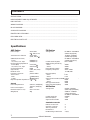
CONTENTS
SPECIFICATION...................................................................................................................................................
MEASUREMENTS AND ADJUSTMENTS .........................................................................................................
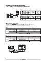
PIN FUNCTION....................................................................................................................................................
WIRING DIAGRAM..............................................................................................................................................
BLOCK DIAGRAM................................................................................................................................................
SCHEMATIC DIAGRAM ....................................................................................................................................
PRINTED CIRCUIT BOARDS.............................................................................................................................
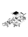
EXPLODED VIEW...............................................................................................................................................
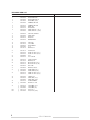
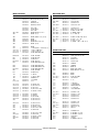
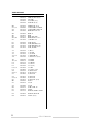
ELECTRICAL PARTS LIST.................................................................................................................................
Specifications
AMP Section
Power output :35 W+35W
(8 , 1kHz, 0.5%)
Total harmonic distirtion
:35 W+35W
(40W, 1kHz, 8 )
S/N Ratio(inout Short) :
Phono :60dB(IHF-A)
CD, Tuner, Aux, Tape :90dB(IHF-A)
Input Sensitivity/Impedance
:
Phono(MM) :2.5mV/47k
CD, Tuner, Aux, Tape :200mV/47k
Channel Separation :60dB
(Input Short) :(1kHz, 1W, B.P.F)
Residual noise
:60mV
Frequency response :20Hz to 65kHz
Tone control :
Bass : 10dB(100Hz)
Treble : 10dB(100Hz)
Required speaker impedance :8 to 16
General
Power Requirements :230V AC, 50Hz[EUR]
120V AC, 60Hz[T/C]
Power Consumption :85W
Dimensions(W x H x D) :215 x 110 x 307
Weight(net) :4Kg
FM Section
Tuning Rane :87.50MHz~ 108.00MHz
(50kHz steps)[EUR]
76.0MHz~ 90.0MHz
(100kHz steps)[DM]
87.50MHz~ 108.00MHz
(100kHz stepe)[T/C]
Usable Sensitivity(IHF) :Mono:15dBf
50dB Quieting Sensitivity :
Mono :30dBf
Stereo :40dBf
Image Reiection Ratio :40dBf
Frequency Response :30Hz~ 15kHz
+0.5dB/-3dB
Distortion(1kHz) :
Mono :0.4%
Stereo :0.5%
Signal-to-Noise Ratio(at 65dBf, 1kHz) :.
Mono :65dB
Stereo :60dB
AM suppression Ratio :40dB
Stereo Separation(1kHz) :30dB
AM Section
Tuning Rane :522kHz~ 1620kHz
(9kHz steps)[EUR/DM]
530MHz~ 1720MHz
(10kHz steps)[T/C]
87.50MHz~ 108.00MHz
Usable Sensitivity :55dB/m
Distortion(1kHz) :1.5%
Signal-to-Noise Ratio :35dB
Standard accessories
Remote control unit
:1
Operator’s manual :1
AM Loop Antenna
:1
FM Antenna :1
FM Matching Transformer :1 (T/C)

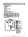
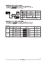
MEASUREMENTS AND
ADJUSTMENTS


SERVICE MANUAL
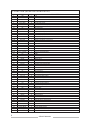
PIN No. SYMBOL I/O DESCRIPTION
1
2
3
4
5
6
7~9
10
11
12
13
14
15
16
17~21
22
23
24
25
26
27
28~29
30
31
32
33
34
35
36
37
38
39
40
41
42
43
44
45
46
47
48
49
50
51~61
62~82
83~85
86
87
88
89
90
91
92
93
94
95~100
Vdd
NC
Func, Mute
NC
Tuner-Nute
Stereo/Mono
Func, Indicator
NC
RDS-DATA
FM-L
RDS-CLK
Stereo-IN
Tuned-IN
Protect-IN
Key Input
Vss
Vass
Varef
Vdd
Back-up
Vss
Func, Up/Down
Vss
XIN
XOUT
RESET
Remote-In
BUS OUT
BUS IN
SPK ON/OFF
NC
-20dB Mute
NC
PLL CE
PLL DATA
PLL CLK
Option
NC
STB
CLK
DATA
NC
Vkk
FIP GRID
FIP ANODE
Option
Option
Option
Option
Standby
VOL OP
VOL DOWN
VOL LED
Power ON/Off
Standby LED
NC
I
-
O
-
O
O
O
-
I
I
I
I
I
I
I
-
-
-
-
I
-
I
-
I
O
I
I
O
I
O
-
O
-
O
O
O
O
-
O
O
O
-
-
O
O
O
O
O
O
O
O
O
O
O
O
+5V
NO Connection
Function Mute ON/OFF Output
No Connection
Tuner Mute Output
Stereo/Mono Switching Output
Function LED Drive Data Output
No connection
RDS DATA Output
FM/AM Switching Output
RDS CLOCK input
Stereo Display input
Tuned Display input
Protection input
Resistor Divide Key Control Input
GND
GND
Vdd(+5V)
+5V
Backup Mode control
GND
Function UP/DOWN INput
GND
Crstal element Connection Terminal
Crstal element Connection Terminal
RESET Input
Remote Control Data Input
System Control Signal Output
System Control Signal Input
Speker ON/OFF Output
NO Connection
-20dB Mute Output
No Connection
PLL Serial Chip Enable Output
PLL Serial Data Output
PLL Serial CLOCK Output
Amp/Receiver Option
No Connection
Function IC Signal Output
Function IC Signal Output
Function IC Signal Output
No Connection
VFLP (-33V)
FIP GRID Output
FIP ANODE Output
Region Option
Display Option
RDS ON/OFF Option
Model Option
Standby/ Direct Option Output
VOL UP
VOL
DOWN
VOL LED Display
Power ON/OFF Output
Standby LED ON/OFF Output
No Connection
IC FUNCTION
(Micom BVITMP87PM78F)
6

7

8
EXPLODED VIEW LIST
£
£
£
£
£
£
£
£
SERVICE MANUAL

9

10

11
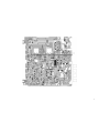
MAIN PCB ASSY
£
£
£
£
£
£
£
£
£
£
£
£
£
£
£
MAIN PCB ASSY
£
£
£
£
£
£
£
£
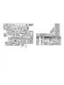
FRONT PCB ASSY
SERVICE MANUAL

12
TUNER PCB ASSY
SERVICE MANUAL

13
INCLUDED ACCESSORIES
SERVICE MANUAL

86745231
E
D
C
B
A
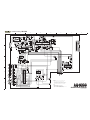
SCHEMATIC DIAGRAM
AG-H300
AM/FM STEREO RECEIVER
AAGG--HH330000
1 st Issue; June 2001
NOTES:
1. Resistor values are in ohms (k=kilo-ohms, M=megohms).
2. Capacitor values are in microfarads (p=picofarads).
3. £Parts marked with this sign are safety critical components.
They must always be replaced with identical components-refer
to the appropriate parts list and ensure exact replacement.
£

86745231
E
D
C
B
A
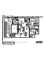
SCHEMATIC DIAGRAM
AG-H300
AM/FM STEREO RECEIVER
AAGG--HH330000
1 st Issue; June 2001
INSTRUCTIONS FOR SERVICE PERSONNEL
BEFORE RETURNING APPLIANCE TO THE CUSTOMER, MAKE LEAKAGE-
CURRENT OR RESISTANCE MEASUREMENTS TO DETERMINE THAT EXPOSED
PARTS ARE ACCEPTABLY INSULATED FROM THE SUPPLY CIRCUIT.
NOTES:
1. Resistor values are in ohms (k=kilo-ohms, M=megohms).
2. Capacitor values are in microfarads (p=picofarads).
3. £Parts marked with this sign are safety critical components.
They must always be replaced with identical components-refer
to the appropriate parts list and ensure exact replacement.
£

86745231
E
D
C
B
A
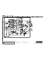
SCHEMATIC DIAGRAM
AG-H300
AM/FM STEREO RECEIVER
AAGG--HH330000
1 st Issue; June 2001
INSTRUCTIONS FOR SERVICE PERSONNEL
BEFORE RETURNING APPLIANCE TO THE CUSTOMER, MAKE LEAKAGE-
CURRENT OR RESISTANCE MEASUREMENTS TO DETERMINE THAT EXPOSED
PARTS ARE ACCEPTABLY INSULATED FROM THE SUPPLY CIRCUIT.
NOTES:
1. Resistor values are in ohms (k=kilo-ohms, M=megohms).
2. Capacitor values are in microfarads (p=picofarads).
3. £Parts marked with this sign are safety critical components.
They must always be replaced with identical components-refer
to the appropriate parts list and ensure exact replacement.
£
-
 1
1
-
 2
2
-
 3
3
-
 4
4
-
 5
5
-
 6
6
-
 7
7
-
 8
8
-
 9
9
-
 10
10
-
 11
11
-
 12
12
-
 13
13
-
 14
14
-
 15
15
-
 16
16


