ページを読み込んでいます...

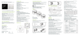
All Models are
available in either
Propane Vapor
Withdrawal,
Butane/Propane,
or Natural Gas
Configurations.
MODELS MAX. INPUT (kW) FUEL
AD060 17.6
AD100 29.3
AD250 73.3
AD325 95.3
Congratulations!
You have purchased the finest agricultural building brood heater available.
Your new L.B. White brood heater incorporates the benefits from the most
experienced manufacturer of heating products using state-of-the-art technology.
We, at L.B. White, thank you for your confidence in our products and
welcome any suggestions or comments you may have...contact us at
001-608-783-5691, or email us at [email protected].
Owner's Manual and Instructions
GUARDIAN ®
Agricultural Animal Confinement Building Brood Heaters
View this manual online at www.lbwhite.com
SCAN THIS QR
CODE
with your smartphone or
visit http://i.youku.com/lbwhite to
view maintenance videos for
L.B.White brood heaters.
ATTENTION ALL USERS
This brood heater has been designed, tested, and evaluated by L.B. White Co. Inc. as
a direct gas fired circulating brood heater for the heating of agricultural animal
confinement buildings. If you are considering using this product for any application
other than its intended use, then please contact your local agent, or the L.B. White
Co., Inc.
150-30344 REV.C
Please refer to important elevation
information on inside cover.

WARNING
Fire and Explosion Hazard
■Not for home or recreational vehicle use.
■Installation of this brood heater in a home
or recreational vehicle may result in a fire
or explosion.
■Fire or explosions can cause property
damage or loss of life.
FOR YOUR SAFETY
If you smell gas:
1. Open windows.
2. Don't touch electrical
switches.
3. Extinguish any open
flame.
4. Immediately call your gas
supplier.
FOR YOUR SAFETY
Do not store or use
gasoline or other
flammable vapors
and liquids in the
vicinity of this or any
other appliance.
WARNING
Fire and Explosion Hazard
■Keep solid combustibles a safe distance away
from the brood heater.
■Solid combustibles include wood or paper
products, feathers, straw, and dust.
■Do not use the brood heater in spaces which
contain or may contain volatile or airborne
combustibles.
■Volatile or airborne combustibles include
gasoline, solvents, paint thinner, dust particles
or unknown chemicals.
■Failure to follow these instructions may result in
a fire or explosion.
■Fire or explosions can lead to property damage,
personal injury or loss of life.
GENERAL HAZARD WARNING
■Failure to comply with the precautions and instructions provided with this brood heater, can
result in:
— Death
— Serious bodily injury or burns
— Property damage or loss from fire or explosion
— Asphyxiation due to lack of adequate air supply or carbon monoxide poisoning
— Electrical shock
■Read this Owner’s Manual before installing or using this brood heater.
■Only properly-trained service people should repair or install this brood heater.
■Save this Owner’s Manual for future use and reference.
■Owner’s Manuals and replacement labels are available at no charge. See website, or for
assistance, contact L.B. White at 001-608-783-5691.
WARNING
■Proper gas supply pressure must be provided to the inlet of the brood heater.
■Refer to dataplate for proper gas supply pressure.
■Gas pressure in excess of the maximum inlet pressure specified at the brood heater inlet can
cause fires or explosions.
■Fires or explosions can lead to serious injury, death, building damage or loss of livestock.
■Gas pressure below the minimum inlet pressure specified at the brood heater inlet may cause
improper combustion.
■Improper combustion can lead to asphyxiation or carbon monoxide poisoning and therefore
serious injury or death to humans.
2
WARNING
■Standard products are manufactured to
operate at optimum efficiency at elevations
between 0 and 610 m above sea level.
■If operated at higher elevations the product
will not function correctly and may function
in an unsafe nature.
■Products providing proper operation for
alternate elevations may be available.
■If you require a high elevation product, did
not specify when ordering, and/or the box
this unit came in does not have an alternate
designation sticker, please contact
Technical Support.

This Owner's Manual includes all accessories commonly
used on this brood heater. However, depending on the
configuration purchased, some accessories may not be
included.
When calling for technical service assistance, or for other
specific information, always have model number,
configuration number and serial number available. This
information is contained on the dataplate. The dataplate is
located on the interior of either the burner end or motor end
door.
This manual will instruct you in the operation and care of
your unit. Have your qualified installer review this manual
with you so that you fully understand the brood heater and
how it functions.
The gas supply line installation, installation of the brood
heater, and repair and servicing of the brood heater requires
continuing expert training and knowledge of gas brood
heaters and should not be attempted by anyone who is not
so qualified. See page 6 for definition of the necessary
qualifications. A detailed Installation and Service Guide is
available, at no charge, to qualified personnel by contacting
the local L.B. White distributor, dealer or the L.B. White
Company.
Contact your local L.B. White distributor or the L.B. White
Co., Inc. for assistance, or if you have any questions about
the use of the equipment or its application.
The L.B. White Co., Inc. has a policy of continuous product
improvement. It reserves the right to change specifications
and design without notice.
SECTION PAGE
General Information . . . . . . . . . . . . . . . . . . . . . . . . . . . . . . . . . . . . . . . . . . . . . . . . . . . . . . . . . . . . . . . . . . .3
Brood Heater Specifications . . . . . . . . . . . . . . . . . . . . . . . . . . . . . . . . . . . . . . . . . . . . . . . . . . . . . . . . . . . .4
Safety Precautions . . . . . . . . . . . . . . . . . . . . . . . . . . . . . . . . . . . . . . . . . . . . . . . . . . . . . . . . . . . . . . . . . . . .5
Installation Instructions
General . . . . . . . . . . . . . . . . . . . . . . . . . . . . . . . . . . . . . . . . . . . . . . . . . . . . . . . . . . . . . . . . . . . . . . . . .7
Air Diverter Installation Instructions . . . . . . . . . . . . . . . . . . . . . . . . . . . . . . . . . . . . . . . . . . . . . . . . . .8
Hanging Installation Instructions . . . . . . . . . . . . . . . . . . . . . . . . . . . . . . . . . . . . . . . . . . . . . . . . . . . . .9
Sediment Trap Assembly Instructions . . . . . . . . . . . . . . . . . . . . . . . . . . . . . . . . . . . . . . . . . . . . . . . . .9
Thermostat Installation Instructions . . . . . . . . . . . . . . . . . . . . . . . . . . . . . . . . . . . . . . . . . . . . . . . . .10
Manual Shut-Off Valve, Hose and Regulator Assembly Instructions . . . . . . . . . . . . . . . . . . . . . . . .10
Start-Up Instructions . . . . . . . . . . . . . . . . . . . . . . . . . . . . . . . . . . . . . . . . . . . . . . . . . . . . . . . . . . . . . . . . .11
Shut-Down Instructions . . . . . . . . . . . . . . . . . . . . . . . . . . . . . . . . . . . . . . . . . . . . . . . . . . . . . . . . . . . . . . .11
Cleaning Instructions . . . . . . . . . . . . . . . . . . . . . . . . . . . . . . . . . . . . . . . . . . . . . . . . . . . . . . . . . . . . . . . . .12
Maintenance Instructions . . . . . . . . . . . . . . . . . . . . . . . . . . . . . . . . . . . . . . . . . . . . . . . . . . . . . . . . . . . . .12
Service Instructions
General . . . . . . . . . . . . . . . . . . . . . . . . . . . . . . . . . . . . . . . . . . . . . . . . . . . . . . . . . . . . . . . . . . . . . . . .13
Motor & Fan Assembly . . . . . . . . . . . . . . . . . . . . . . . . . . . . . . . . . . . . . . . . . . . . . . . . . . . . . . . . . . . .13
Air Proving Switch . . . . . . . . . . . . . . . . . . . . . . . . . . . . . . . . . . . . . . . . . . . . . . . . . . . . . . . . . . . . . . . .14
Flapper (Sail) AD325 . . . . . . . . . . . . . . . . . . . . . . . . . . . . . . . . . . . . . . . . . . . . . . . . . . . . . . . . . . . . .14
Igniter & Flame Sensor Assembly . . . . . . . . . . . . . . . . . . . . . . . . . . . . . . . . . . . . . . . . . . . . . . . . . . .15
High Limit Switch . . . . . . . . . . . . . . . . . . . . . . . . . . . . . . . . . . . . . . . . . . . . . . . . . . . . . . . . . . . . . . . .16
Burner Orifice and Gas Control Valve . . . . . . . . . . . . . . . . . . . . . . . . . . . . . . . . . . . . . . . . . . . . . . . .17
Ignition Control . . . . . . . . . . . . . . . . . . . . . . . . . . . . . . . . . . . . . . . . . . . . . . . . . . . . . . . . . . . . . . . . . .17
Transformer . . . . . . . . . . . . . . . . . . . . . . . . . . . . . . . . . . . . . . . . . . . . . . . . . . . . . . . . . . . . . . . . . . . . .17
Gas Pressure Checks . . . . . . . . . . . . . . . . . . . . . . . . . . . . . . . . . . . . . . . . . . . . . . . . . . . . . . . . . . . . . . . .18
Troubleshooting Instructions . . . . . . . . . . . . . . . . . . . . . . . . . . . . . . . . . . . . . . . . . . . . . . . . . . . . . . . . . . .19
Electrical Connection and Ladder Diagram . . . . . . . . . . . . . . . . . . . . . . . . . . . . . . . . . . . . . . . . . . . . . . .24
Brood Heater Component Function . . . . . . . . . . . . . . . . . . . . . . . . . . . . . . . . . . . . . . . . . . . . . . . . . . . . .25
Parts Identification (Parts List & Schematic) AD060/AD100 . . . . . . . . . . . . . . . . . . . . . . . . . . . .26 & 27
Parts Identification (Parts List & Schematic) AD250 . . . . . . . . . . . . . . . . . . . . . . . . . . . . . . . . . . .28 & 29
Parts Identification (Parts List & Schematic) AD325 . . . . . . . . . . . . . . . . . . . . . . . . . . . . . . . . . . .30 & 31
Warranty Policy ,Replacement Parts and Service . . . . . . . . . . . . . . . . . . . . . . . . . . . . . . . . . . . . . . . . . .32
Table of Contents
General Information
3

4
Brood Heater Specifications
PROPANE GAS(kg)
NATURAL GAS(m3)
BUTANE /PROPANE (kg)
SPECIFICATIONS Model
Burner Manifold
Pressure
(kPa/mbar/Inches W.C.)
Electrical Supply
(Volts/Hz/Phase)
Amp Draw
Dimensions L x W x H (cm)
Minimum Safe Distances
From Nearest Combustible
Materials
STARTING
CONTINUOUS
Motor Characteristics
(Watts/RPM)
Ball Bearing
1.83 m
220-240/50/1
Maximum Input per hour (kW)
Gas Supply Pressure
Acceptable at the Inlet
of the Brood Heater for
Purpose of Input
Adjustment
(kPa/mbar/Inches W.C.)
PROPANE GAS
NATURAL GAS
BUTANE /PROPANE
MAX.
MIN.
MAX.
MIN.
Ventilation Air Required to Support
Combustion (m3/hour)
PROPANE GAS
NATURAL GAS
BUTANE/
PROPANE
MAX.
MIN.
Note: Butane / propane models are configured to produce full rate output when running on BUTANE fuel. When the brood
heater is operating on PROPANE as the fuel, the heating rate of the unit will be approximately 11 % less than full rated output.
Gas Consumption per Hour
AD060 AD100 AD250 AD325
17.6 29.3 73.3 95.3
408 680 1,869 2,888
2.50/25.5/10.0 --
1.0/10.0/4.0 0.87/8.7/3.5
2.00/20.0/8.0 2.24/22.4/9.0 --
3.40 /34.0/13.5
2.74/27.4/11.0
3.40/34.0/13.5
1.75/17.5/7.0
3.40/34.0/13.5 --
2.74/27.4/11.0 --
50 /1450 150 /1300 186/1150 373/950
1.2 2.0 3.5 5.4
0.4 1.2 2.6 2.6
54 x 36 x 46 75 x 36 x 46 78 x 46 x 72 91.5 x 56.5 x 76
TOP 0.3 m
SIDES 0.3 m
BACK 0.3 m
BLOWER OUTLET
GAS L.P. Gas Supply — 1.83 m
SUPPLY Natural Gas Supply — N/A
1.26 2.10 5.26 --
1.70 2.83 7.08 9.20
1.26 2.10 5.26 --

LPG and natural gas have man-made odorants added specifically for detection of fuel gas leaks.
If a gas leak occurs, you should be able to smell the fuel gas.
THAT’S YOUR SIGNAL TO GO INTO IMMEDIATE ACTION!
■Do not take any action that could ignite the fuel gas. Do
not operate any electrical switches. Do not pull any
power supply or extension cords. Do not light matches
or any other source of flame. Do not use your
telephone.
■Get everyone out of the building and away from the area
immediately.
■Close all LPG gas tank or cylinder fuel supply valves, or
the main fuel supply valve located at the meter if you
use natural gas.
■LPG is heavier than air and may settle in low areas.
When you have reason to suspect a propane leak, keep
out of all low areas.
■Use your neighbor’s phone and call your fuel gas
supplier and your fire department. Do not re-enter the
building or area.
■Stay out of the building and away from the area until
declared safe by the firefighters and your fuel gas
supplier.
■FINALLY, let the fuel gas service person and the
firefighters check for escaped gas. Have them air out
the building and area before you return. Properly
trained service people must repair the leak, check for
further leakages, and then relight the appliance for you.
■Some people cannot smell well. Some people cannot
smell the odor of the man-made chemical added to LPG
or natural gas. You must determine if you can smell the
odorant in these fuel gases.
■Learn to recognize the odor of LPG and natural gas.
Local LPG dealers will be more than happy to give you a
scratch and sniff pamphlet. Use it to become familiar
with the fuel gas odor.
■Smoking can decrease your ability to smell. Being
around an odor for a period of time can affect your
sensitivity to that particular odor.
■The odorant in LPG and natural gas is colorless and the
intensity of its odor can fade under some
circumstances.
■If there is an underground leak, the movement of gas
through the soil can filter the odorant.
■LPG odor may differ in intensity at different levels.
Since propane gas is heavier than air, there may be
more odor at lower levels.
■Always be sensitive to the slightest gas odor.If you
continue to detect any gas odor, no matter how small,
treat it as a serious leak. Immediately go into action as
discussed previously.
Safety Precautions
ODOR FADING -- NO ODOR DETECTED
ATTENTION -- CRITICAL POINTS TO REMEMBER!
■LPG has a distinctive odor. Learn to recognize these
odors. (Reference Fuel Gas Odor and Odor Fading
sections above.
■
If you have not been properly trained in repair and service
of LPG and natural gas brood heaters, then do not
attempt to light the heater, perform service or repairs, or
make any adjustments to the brood heater on the fuel
system.
■Even if you are not properly trained in the service and
repair of the brood heater, ALWAYS be consciously
aware of the odors of LPG and natural gas.
■A periodic sniff test around the heater or at the brood
heater’s joints; i.e. hose, connections, etc., is a good
safety practice under any conditions. If you smell even a
small amount of gas, CONTACT YOUR FUEL GAS
SUPPLIER IMMEDIATELY. DO NOT WAIT!
WARNING
■Do not use this brood heater for heating human living
quarters.
■Do not use in unventilated areas.
■The flow of combustion and ventilation air must not be
obstructed.
■Proper ventilation air must be provided to support the
combustion air requirements of the brood heater being
used.
■Refer to the specification section of the brood heater’s
Owner’s Manual, heater dataplate, or contact the
L.B. White Company to determine combustion air
ventilation requirements of the brood heater.
■Lack of proper ventilation air will lead to improper
combustion.
■Improper combustion can lead to carbon monoxide
poisoning leading to serious injury or death.
Symptoms of carbon monoxide poisoning can include
headaches, dizziness and difficulty in breathing.
■Symptoms of improper combustion affecting livestock
can be disease, lower feed conversion, or death.
Asphyxiation Hazard
5

1. Do not attempt to install, repair, or service this brood
heater or the gas supply line unless you have
continuing expert training and knowledge of gas
heaters.
Qualifications for service and installation of this
equipment are as follows:
a.
To be a qualified gas brood heater service person,
you must have sufficient training and experience
to handle all aspects of gas-fired brood heater
installation, service and repair. This includes the
task of installation, troubleshooting, replacement
of defective parts and testing of the brood heater.
You must be able to place the brood heater into a
continuing safe and normal operating condition.
You must completely familiarize yourself with each
model brood heater by reading and complying with
the safety instructions, labels, Owner’s Manual,
etc., that is provided with each heater.
b.
To be a qualified gas installation person, you must
have sufficient training and experience to handle
all aspects of installing, repairing and altering gas
lines, including selecting and installing the proper
equipment, and selecting proper pipe and tank
size to be used. This must be done in accordance
with all local, state and national codes as well as
the manufacturer’s requirements.
2. All installations and applications of L.B. White brood
heaters must meet all relevant local, state and
national codes. Included are LPG, natural gas,
electrical, and safety codes. Your local fuel gas
supplier, a local licensed electrician, the local fire
department or similar government agencies, or your
insurance agent can help you determine code
requirements.
3. Do not move, handle, or service the brood heater
while in operation or connected to a power or fuel
supply.
4. This brood heater may be installed in areas subject to
washdown. This brood heater may only be washed on
the external case assembly—see Cleaning
Instructions. Do not wash the interior of the brood
heater. Use only compressed air, soft brush or dry
cloth to clean the interior of the brood heater and it’s
components. After external washdown, do not
operate this brood heater until it is completely dry. In
any event, do not operate the brood heater for at
least one hour after external washdown.
5. For safety, this brood heater is equipped with a
manual reset high-limit switch and an air proving
switch. Never operate this brood heater with any
safety device that has been bypassed. Do not
operate this brood heater unless all of these features
are fully functioning.
6. Do not operate the brood heater with its door open or
panel removed.
7. Do not locate fuel gas containers or fuel supply hoses
anywhere near the blower outlet of the brood heater.
8. Do not block air intakes or discharge outlets of the
brood heater. Doing so may cause improper
combustion or damage to brood heater components
leading to property damage or animal loss.
9. The hose assembly shall be visually inspected on an
annual basis. If it is evident there is excessive
abrasion or wear, or if the hose is cut, it must be
replaced prior to the heater being put into operation.
The hose assembly shall be protected from animals,
building materials, and contact with hot surfaces
during use. The hose assembly shall be that
specified by the manufacturer. See parts list.
10. Check for gas leaks and proper function upon brood
heater installation, before building repopulation or
when relocating.
11. This brood heater should be inspected for proper
operation by a qualified service person before
building repopulation and at least annually.
12. Always turn off the gas supply if the brood heater is
not going to be used.
13. This brood heater is wired for a three-wire electrical
system. There is a hot lead, neutral lead and ground
lead. The brood heater may or may not incorporate a
plug in the power cord to the brood heater and the
plug may or may not incorporate a pin for the ground
wire. In any case, the brood heater must be properly
connected into a grounded electrical supply using the
ground lead in the power cord. Failure to use a
properly grounded electrical supply can result in
electrical shock, personal injury or death.
14. Direct ignition brood heaters will make up to three
trials for ignition. If ignition is not achieved, the
control system will lock out the gas control valve. If
gas is smelled after system lock out has occurred,
immediately close all fuel supply valves. Do not
relight until you are sure that all gas that may have
accumulated has cleared away. In any event, do not
relight for at least 5 minutes.
15. In a hanging type installation, rigid pipe or copper
tubing coupled directly to the brood heater may cause
gas leaks during movement, and therefore must not
be used. Use only gas hose assemblies that are
rated and approved for L.P.gas and natural gas in a
hanging type of installation.
16. Installations not using the gas hose supplied with
this appliance must connect dimensionally using
American National Standard Wrought Steel and
Wrought Iron Pipe B36/10-1970. (Aluminum piping
or tubing shall not be used.) Copper tubing when
used for conveying natural gas, shall be internally
tinned or equivalently treated to resist sulphur.
6

1. Read all safety precautions and follow L. B. White
recommendations when installing this brood heater.
If during the installation or relocating of the brood
heater, you suspect that a part is damaged or
defective, call a qualified service agency for repair or
replacement.
2.
Make sure the brood heater is properly positioned
before use and is hung level. Observe and obey all
minimum safe distances of the heater to the nearest
combustible materials. Minimum safe distances are
given on the brood heater nameplate and on page 4 of
this manual.
3. The brood heater may be installed either indoors or
outdoors. When the brood heater is mounted
outdoors, use only the ductwork supplied in the
outdoor mounting kit.
4. For brood heaters intended for outdoor installation,
the brood heater is to be installed at least 18 inches
above the ground or to a height that would prevent
snow blockage of brood heater’s air inlet.
5.
The brood heater must have the proper gas regulator
installed for the application. A regulator must be
connected to the gas supply so that gas pressure at the
inlet to the gas valve is regulated within the range
specified on the dataplate at all times. Contact your
gas supplier, or the L.B. White Co., Inc. if you have any
questions.
6. The brood heater’s gas regulator (with pressure relief
valve) should be installed outside of building. Any
regulators inside the buildings must be properly
vented to the outside. Local, state and national
codes always apply to regulator installation.
7.
All gas pressure regulators must be installed in strict
accordance with the manufacturer’s safety instructions.
These instructions accompany each regulator.
8. Insure that all accessories that ship within the brood
heater have been removed from inside of heater and
installed. This pertains to air diverters, hose,
regulators, etc.
9. Make certain that a sediment trap is installed at the
gas valve inlet to prevent foreign materials (pipe
compound, pipe chips and scale) from entering the
gas valve. Debris blown into the gas valve may cause
that valve to malfunction resulting in a serious gas
leak that could result in a possible fire or explosion
causing loss of products, building or even life. A
properly installed sediment trap will keep foreign
materials from entering the gas valve and protect the
safe functioning of that important safety component.
10. Any brood heater connected to a piping system must
have an accessible, approved manual shut off valve
installed within 1.83 m of the brood heater it serves.
11. Check all connections for gas leaks using approved
gas leak detectors. Gas leak testing is performed as
follows:
-- Check all pipe connections, hose connections,
fittings and adapters upstream of the gas
control with approved gas leak detectors.
-- In the event a gas leak is detected, check the
components involved for cleanliness and
proper application of pipe compound before
further tightening.
-- Furthermore tighten the gas connections as
necessary to stop the leak.
-- After all connections are checked and any
leaks are stopped, turn on the main burner.
-- Stand clear while the main burner ignites to
prevent injury caused from hidden leaks that
could cause flashback.
-- With the main burner in operation, check all
connections, hose connections, fittings and
joints as well as the gas control valve inlet and
outlet connections with approved gas leak
detectors.
-- If a leak is detected, check the components
involved for cleanliness in the thread areas
and proper application of pipe compound
before further tightening.
-- Tighten the gas connection as necessary to
stop the leak.
WARNING
Fire or explosion hazard.
Can cause property damage, severe injury or death.
1. Disconnect power supply before wiring to prevent
electrical shock or equipment damage.
2. To avoid dangerous accumulation of fuel gas, turn
off gas supply at the appliance service valve before
starting installation, and perform gas leak test after
completion of installation.
3. Do not force the gas control knob. Use only your
hand to turn the gas control knob. Never use any
tools. If the knob will not operate by hand, the
control should be replaced by a qualified service
technician. Force or attempted repair may result in
fire or explosion.
7
Installation Instructions
GENERAL
WARNING
Fire and Explosion Hazard
■Do not use open flame (matches, torches, candles,
etc.) in checking for gas leaks.
■Use only approved leak detectors.
■Failure to follow this warning can lead to fires or
explosions.
■Fires or explosions can lead to property damage,
personal injury or loss of life.

-- If necessary, replace the parts or components
involved if the leak cannot be stopped.
-- Ensure all gas leaks have been identified and
repaired before proceeding.
12. A qualified service agency must check for proper
operating gas pressure upon installation of the brood
heater.
13. Light according to instructions on the brood heater or
within owner's manual.
14. It is extremely important to use the proper size and
type of gas supply line to assure proper functioning of
the brood heater. Contact your fuel gas supplier for
proper line sizing and installation.
15. This brood heater can be configured for use with
propane gas, propane/butane gas mix, or natural gas.
Consult the dataplate, located on interior of the burner
end or motor end door, for the gas configuration of the
specific brood heater. Do not use the brood heater in
a propane liquid withdrawal system or application. If
you are in doubt, contact the L.B. White Co., Inc.
16. Eventually, like all electrical/mechanical devices, the
thermostat can fail. Thermostat failure may result in
either an underheating or overheating condition which
may damage critical products and/or cause animal
injury or death. Critical products and/or animals
should be protected by a separate back-up control
system that limits high and low temperatures and also
activates appropriate alarms.
17. Take time to understand how to operate and maintain
the brood heater by using this Owner’s Manual. Make
sure you know how to shut off the gas supply to the
building and also to the individual brood heater.
Contact your fuel gas supplier if you have any
questions.
18. Any defects found in performing any of the service or
maintenance procedures must be eliminated and
defective parts replaced immediately. The brood
heater must be retested by properly qualified service
personnel before placing the brood heater back into
use.
19. Do not exceed input rating stamped on the dataplate
of the brood heater. Do not exceed the burner
manifold pressure stated on the dataplate. Do not
use an orifice size different than specified for the
specific input rating of this brood heater, fuel type
configuration and altitude.
1. Air diverters can be installed in the brood heater
outlet to provide direction to the heated air as it exits
the brood heater. Installation options include
installing the diverters in such a way as to broadly
distribute the air in two 45 degree paths or to focus
the air flow in one 45 degree direction. See Fig. 1.
2. The air diverters may require hand forming prior to
installation. Make 90 degree bends utilizing the
performations provided. The diverter should then
have the shape shown in Fig. 1.
3. The air diverter’s tabs on each half will pop into the
blower outlet between the inside of the case
assembly and the blower housing outlet. If the
notched tabs do not pop into the blower outlet,
loosen (do not remove) the blower outlet screws.
Doing this provides a gap into which you can insert
the tabs. Retighten the screws after installation.
FIG. 1 (Typical installation allowing two directions of air movement.)
(Appearance of the outlet on brood heater may vary from model to model.)
AIR DIVERTER
INSTALLATION INSTRUCTIONS
Accessory- must be ordered separately
Alternate Air Diverter Installations
TABS
DIVERTER
HALVES
OUTLET
SCREWS
FORMED
OUTLET GUARD
NOTCHES IN MOUNTING TABS
8

1. Assemble according to the illustration and tighten all
eyebolts securely. See Fig. 2.
FIG. 2
2. Be sure the brood heater is securely fastened and is
hanging level. (Check crosswise and lengthwise.)
3. See Fig. 3 for typical indoor installation. In any
animal confinement building, consideration must be
given to making sure the brood heater is located away
from the livestock so that livestock cannot knock the
brood heater, tear it loose from its mounting, or
damage the brood heater or its gas supply line in any
way. Make sure you observe and obey minimum
clearance distances to combustible materials as
stated in the specification section of this owner’s
manual and on the brood heater itself.
FIG. 3
Assemble the tee, nipples and cap together and tighten
securely. See Fig. 4. The sediment trap assembly must
always be mounted in a vertical position. Make sure pipe
thread compound that is resistant to both L.P. gas and
natural gas is used in making all connections. Check all
connections for gas leaks using approved gas leak
detectors.
FIG. 4
9
HANGING INSTRUCTIONS
Accessory- must be ordered separately
SEDIMENT TRAP ASSEMBLY
NIPPLE
HOSE ADAPTER
TEE
NIPPLE
CAP
TO GAS CONTROL
VALVE INLET
EYEBOLT
NUT
FLAT WASHER
CAGE NUT
CHAIN
CASE TOP
NOTE: REGULATORS SHOULD ALWAYS BE MOUNTED OUTDOORS. IF
CIRCUMSTANCES FORCE INSTALLING THE REGULATOR INDOORS,
THE REGULATOR'S VENT MUST BE VENTED OUTDOORS USING VENT
LINE NO SMALLER THAN VENT OPENING.
VENT OF REGULATOR MUST
POINT DOWN AND REGULATOR
MUST BE VENTED OUTDOORS
MANUAL SHUT-OFF VALVE
CAN BE INSTALLED BEFORE
THE REGULATOR, UNDER
THE EAVE OF THE BUILDING,
OR AFTER THE REGULATOR
INSIDE THE BUILDING.
OPTIONAL INDOOR
REGULATOR
MOUNTING LOCATION
GAS HOSE
THERMOSTAT
CORD
YOKE
HEATER
THERMOSTAT 1 FT.
BLACK PIPE
THROUGH WALL
VENT LINE
WALL OUTLET
POWER CORD
SEDIMENT
TRAP
WALL
CHAIN OR CABLE
1 FT.
0.3 m 0.3 m
BROOD
HEATER

To Connect the Direct Wired Thermostat Kit to the
Control Box on the Brood Heater:
a. Open the control box.
b. Remove the yellow wire connected between the
24 volt output of the transformer and terminal W
of the ignition control.
c. Remove the plastic hole plug at the back or
bottom of the control box. Run the wiring of the
thermostat kit through this hole.
d. Connect the black lead of the thermostat kit to
the 24 volt output terminal of the transformer.
e. Connect the white lead of the thermostat kit to
terminal W of the ignition control.
f. Install the strain relief (supplied on thermostat
cordset) around the cord at the entry hole of the
control box.
g. Close and latch the control box.
h. Start the brood heater and check for proper
operation.
WARNING
Electrical Shock Hazard
■Disconnect the electrical supply before connecting the
thermostat to the brood heater.
■Failure to follow this warning can result in electrical
shock, leading to personal injury or death.
10
THERMOSTAT INSTALLATION
Accessory- must be ordered separately
MANUAL SHUT-OFF VALVE, HOSE
AND REGULATOR ASSEMBLY
Accessory- must be ordered separately
REGULATOR
NIPPLE
VALVE, MANUAL
SHUT-OFF
GAS HOSE
ADAPTER
SEDIMENT TRAP
TO CONTROL
VALVE INLET
REGULATOR VENT
GAS FLOW
1. Always use approved pipe thread compound suitable
for use with L.P. gas or natural gas on the threaded
connections.
2. Assemble the components together according to the
figure. This view is to show general assembly of the
components only. The regulator must always be
mounted so its vent, regardless of location on the
regulator, is always pointed downward.
3. Tighten all connections securely.
4. Check all connections for gas leaks using approved
gas leak detectors.
FIG. 5

Follow steps 1 - 6 on initial start-up after brood heater
installation by a qualified gas heater service person. For
normal start-up, simply turn thermostat above room
temperature. The brood heater will start.
1. Open all manual fuel supply valves and check for gas
leaks using approved leak detectors. The gas control
valve on the brood heater has a manual shut-off
feature incorporated into the valve assembly. Make
sure the indicator on the valve is turned to the “on”
position. See Fig. 6.
FIG. 6
2. Connect the electrical cord to an approved electrical
outlet.
3. Set the thermostat (if supplied) to desired room
temperature.
4. This brood heater includes a direct ignition control
module for purposes of controlling the timing of the
ignition process of the heater as well as monitoring of
the safety functions. The control module is contained
within the control enclosure. On the control module
is a red light emitting diode (LED). This LED indicates
the status of the brood heater. The LED is visible
external of the control enclosure through the viewing
window. A constant light from the LED is an indicator
that the brood heater is functioning correctly. Any
flash pattern by the LED is indicative that there is a
problem in the operation of the brood heater. Refer
to the troubleshooting decal on the access panel at
the fan motor end of the brood heater for assistance
in troubleshooting. Only qualified and properly
trained personnel shall service or repair the brood
heater.
5. On a call for heat, the motor will start up and run for
five (5) seconds. This “pre-purge” is a safety feature
and a normal operational characteristic prior to
ignition taking place. After five (5) seconds, the
igniter will begin to spark.
NOTE: It is normal for air to be trapped in the gas
hose on new installations. The brood heater
may attempt more than one trial for ignition
before the air is finally purged from the line
and ignition takes place.
6. The ignition control will make up to three trials for
ignition. Each trial for ignition will take approximately
ten (10) seconds. The first three trials for ignition will
occur within 40 seconds if ignition is not achieved. A
15 minute “wait period” will then begin after the third
trial for ignition has taken place. After the 15 minute
time span has elapsed, three more trials for ignition
will take place. If ignition is not achieved at this final
trial, the system will “lock out”, and a three flash
pattern will be indicated by the LED.
If the brood heater is to be shut down for cleaning,
maintenance or repair, follow steps 1 - 5. Otherwise, simply
turn thermostat to “off” or “no heat” for standard shut
down.
1. Close all manual fuel supply valves.
2. With the brood heater lit, allow heater to burn off
excess fuel in gas supply hose.
3. Turn the indicator on the gas control to “off”.
4. Turn thermostat to “off” or “no heat” position.
5. Disconnect the brood heater from the electrical
supply.
11
Start-Up Instructions
Shut-Down Instructions
ON
OFF

1. Before cleaning, shut off all gas supply valves and
disconnect electrical supply.
2. The brood heater should have dirt or dust removed
periodically:
a. After each flock or between building re-
population, give the brood heater a general
cleaning using compressed air or a soft brush on
its interior and exterior. At this time, dust off the
motor case to prevent
the motor from over-heating
and shutting the brood heater down.
b. At least once a year, give the brood heater a
thorough cleaning. At this time, remove the fan
and motor assembly and brush or blow off the fan
wheel, giving attention to the individual fan
blades. Additionally, make sure the burner air
inlet venturi ports and the throat of the casting
are free of dust accumulation and the area
between the heat chamber top and inside case is
also free of dust.
c. When washing with water, observe and obey the
Warning within these Cleaning Instructions. This
same Warning is also supplied on the brood
heater.
WARNING
This brood heater may be washed only on the external
case assembly provided:
A. The brood heater is disconnected from the electrical
supply.
B. All access panels are securely closed.
C. Water spray nozzle shall not discharge within 1.83 m
of the brood heater.
D. The water pressure does not exceed 3.1 BAR for 10
seconds on each side of the brood heater.
E. The brood heater is not reconnected to electrical
supply for a minimum of 1 hour or until the brood
heater is thoroughly dry.
Improper cleaning of the brood heater can cause severe
personal injury or property damage due to water and/or
cleaning solution:
1. In electrical components, connections and wires
causing electrical shock or component failure.
2. On gas control components causing corrosion which
can result in gas leaks and fire or explosion from the
leak.
Clean internal components of the brood heater with a
soft, dry brush or cloth, or compressed air.
12
Cleaning Instructions
WARNING
Fire, Burn, and Explosion Hazard
■This brood heater contains electrical and mechanical components in the gas management, safety and airflow systems.
■Such components may become inoperative or fail due to dust, dirt, wear, aging, or the corrosive atmosphere of an
animal confinement building.
■Periodic cleaning and inspection as well as proper maintenance are essential to avoid serious injury or property
damage.
1. Have your gas supplier check all gas piping annually
for leaks or restrictions in gas lines. Also, at this time
have your gas supplier clean out the sediment trap of
any debris that may have accumulated.
2. The brood heater’s surrounding area shall be kept
clear and free from combustible materials, gasoline,
and other flammable vapors and liquids.
3. Regulators can wear out and function improperly.
Have your gas supplier check the date codes on all
regulators installed and check delivery pressures to
the appliance to make sure that the regulator is
reliable.
4. Regulators must be periodically inspected to make
sure the regulator vents are not blocked. Debris,
insects, insect nests, snow, or ice on a regulator can
block vents and cause excess pressure at the
appliance.
5. Review all brood heater markings (ie. warnings, start-
up/shutdown, electrical wiring, diagrams, etc.) for
legibility. Ensure that none are cut, torn, or otherwise
damaged. Any damaged markings must be replaced
immediately by contacting L.B. White Co., Inc.
Markings are available at no cost.
6. Inspect gas hoses for nicks,cuts, or corroded fittings.
Replace the complete gas hose assembly if defects
are found.
7. Inspect the brood heater’s electrical connections.
Replace any terminals that are corroded.
Maintenance Instructions

13
1. Remove the motor mounting plate screws and lift the
fan and motor assembly from the housing. See Fig. 7,
AD250 shown.
2. Loosen the square head set screw(s) on the fan
wheel.
3. Pull the fan wheel from the motor shaft. Use a wheel
puller if necessary.
4. Remove the four (4) nuts securing the motor to the
mounting plate.
FIG. 7
-- Fan wheel to motor mount plate spacing must be
adjusted to the clearance specified in the table
below before tightening the fan wheel to the motor
shaft.
-- Make sure that set screw(s) of the fan are on the
flats of motor shaft when tightening.
FIG. 8
MOTOR MOUNT PLATE FAN WHEEL
CLEARANCE
MOTOR
6 mm AD060/AD100
3 mm AD250/AD325
SCREWS
Service Instructions
1. Close the fuel supply valve to the brood heater and
disconnect the electrical supply before servicing unless
necessary for your service procedure.
2. Clean the brood heater’s orifice with compressed air or
a soft, dry rag. Do not use files, drills, broaches, etc. to
clean the orifice hole. Doing so will enlarge the hole,
causing combustion or ignition problems. Replace the
orifice if it cannot be cleaned properly.
3. The high limit switch can be tested by disconnecting the
leads at the component, and jumpering the leads
together.:
-- Reconnect the electrical supply and open fuel
supply valves.
-- If the brood heater lights, the component is defective
and must be replaced.
-- Do not leave the jumper on or operate the brood
heater if the part is defective. Replace the part
immediately.
-- An alternate method for checking the components
is to perform a continuity check.
4. The air proving switch must not be jumpered. If
jumpered, the ignition control will not allow brood
heater operation. Test the air proving switch for
continuity. If defective, replace the switch.
5. Open the respective case panel for access to burner or
fan related components. Open the control box for
access to the ignition control, and transformer.
6. Disconnect the appropriate electrical leads when
replacing components.
7. For reassembly, reverse the respective service
procedure. Ensure gas connections are tightened
securely.
8. After servicing, start the brood heater to ensure proper
operation and check for gas leaks.
WARNING
Fire and Explosion Hazard
■Do not disassemble or attempt to repair any brood
heater components or gas train components.
■All component parts must be replaced if defects are
found.
■Failure to follow this warning will result in fire or
explosions, causing property damage, injury, or
death.
GENERAL
WARNING
Burn Hazard
■Brood heater surfaces are hot for a period of time
after the heater has been shut down.
■Allow the brood heater to cool before performing
service, maintenance, or cleaning.
■Failure to follow this warning will result in burns
causing injury.
MOTOR AND FAN WHEEL ASSEMBLY

AIR PROVING SWITCH
The air proving switch is located on the fan housing at
the motor end of the brood heater. It must work properly
to allow an ignition cycle. If the air proving switch
contacts are closed before the igntion control starts the
fan motor, or do not close on a call for heat after the fan
motor starts, ignition will not occur . See Fig. 9a or 9b.
AW060/AW100/AW250 service (Fig. 9a):
-- Remove the two (2) sheet metal screws holding
the switch with bracket to blower housing.
-- Remove the assembly by turning the switch so the
paddle on the switch arm can be pulled through
the oblong hole on side of fan housing.
AW325 service (Fig. 9b):
-- Remove the two mounting nuts and slide the
switch from its mounting screws.
FIG. 9a
Fig. 9b
AIR PROVING SWITCH
FLAPPER (SAIL)
The flapper, located within the housing at the blower
discharge, works in conjunction with the air proving
switch in proving that proper air flow has been achieved
by the fan and motor before allowing an ignition cycle to
continue.
If the flapper is binding, its arm will not engage the air
proving switch and ignition will not occur.
Ensure the flapper lifts freely, that it does not bind on the
fan housing and that it is free of dust and other debris.
FIG. 10
REMOVE
NUTS
REMOVE COVER
(AD325 ONLY)
14

15
■Refer to Fig. 11 (AD100/250) or Fig. 12 (AD060) for
servicing of the igniter assembly.
■The igniter/sensor assembly may require cleaning due
to accumulations of dust and dirt over a period of
time, affecting its ability to ignite fuel gas and sense
burner flame. Cleaning will require igniter/sensor
removal.
-- If spark appears to be weak, rub the igniter
electrode with emery cloth or steel wool to remove
any buildup.
--- If the spark appears strong but the brood heater
cycles off, rub the sensor rod with emery cloth or
steel wool to remove any build-up.
■Ensure the igniter gap to burner is 3 mm and the
igniter tip is positioned over the burner port according
to the illustration below.
IGNITER AND FLAME SENSOR ASSEMBLY
SENSOR IGNITER
2.5 mm - 4.5 mm
HEAT CHAMBER FACE
BURNER
IGNITER LEAD
SENSOR LEAD
IGNITER / SENSOR
ENCLOSURE
TO REMOVE IGNITER / SENSOR WITH ENCLOSURE
REMOVE SCREW, LIFT ASSEMBLY
FROM ITS MOUNTING SLOTS
TO GAP IGNITER LOOSEN SCREW.
MOVE ENCLOSURE UP OR DOWN
TO ALLOW PROPER POSITIONING
OF IGNITER TO BURNER.
FIG. 11
3 mm GAP to BURNER
LOOSEN SCREW AND SLIDE
ASSEMBLY UP/DOWN TO MAINTAIN
PROPER GAP.
REMOVE SCREW AND SLIDE THE ENCLOSURE’S
MOUNTING TABS FROM SLOTS IN HEAT CHAMBER.
IGNITER ENCLOSURE
SENSOR IGNITER
HEAT CHAMBER
BURNER
BURNER
17,6 kW: 3 mm
65,9 kW: 4 mm IGNITER
FLAME SENSOR
REMOVE SCREW (65,9 kW MODEL ONLY)
REMOVE SCREWS
IGNITER/SENSOR
ENCLOSURE
BURNER
HEAT CHAMBER
LOOSEN SCREWS AND SLIDE IGNITER
UP/DOWN TO MAINTAIN PROPER GAP.
REMOVE SCREWS AS NEEDED FOR
SERVICING IGNITER ASSEMBLY
BURNER
BURNER
IGNITER / SENSOR
ENCLOSURE
HEAT CHAMBER
IGNITER
3 mm FLAME SENSOR
FIG. 12

This brood heater uses a high limit heat switch for the
purpose of over heat protection. It is connected between the
ignition control and the gas control valve.
The switch has normally closed contacts. If an overheat
condition occurs, the switch contacts will open, thereby
opening the circuit to the gas control valve.
Model AD060/AD100/AD250: The high limit switch is located
on the heat chamber, See Fig. 13 a and 13b.
ModelAD325: The high limit switch is located on the fan
housing side panel at the motor end of the heater. See Fig.
14 a and 14 b.
The high limit switch should be tested a minimum of once per
year when the heater is given a thorough cleaning.
1. Remove the switch. Holding the switch by one of its
mounting legs, apply a small flame only to the sensing
portion on the back of the switch. See Fig. 15. Do not
melt the plastic housing of the switch when
conducting this test.
2. Within a minute, you should hear a pop coming from
the switch, which indicates the contacts of the switch
have opened. Check for lack of electrical continuity
across the switch terminals to verify contacts have
opened.
3. Allow the switch cool down for about a minute before
firmly pressing the reset button on the switch.
4. Check for electrical continuity across the switch
terminals to make sure the contacts have closed.
5. Reinstall the switch back into the brood heater.
Reconnect the brood heater to its electrical supply.
Start the brood heater and check for proper operation.
FIG. 15
MANUAL RESET HIGH LIMIT SWITCH
WARNING
Fire Hazard
■Do not operate the brood heater with the high limit
switch bypassed.
■Operating the brood heater a bypassed high limit
switch may lead to overheating, possibly resulting in a
fire, with subsequent damage to the brood heater,
building damage, or loss of livestock.
RESET BUTTON
SENSING
SURFACE
TERMINAL
FLAME
MOUNTING
LEG
HIGH LIMIT SWITCH
(AD100/AD250)
16
HIGH LIMIT SWITCH
(AD060)
REMOVE COVER
SWITCH
(AD325)
FIG. 14a FIG. 14b
FIG. 13a FIG. 13b

The control sends and receives voltages to operate or verify
operation of components. Refer to the following and Fig. 19 to
understand the ignition control’s terminal designators if doing
voltage checks on the control.
L1: 220 VAC to control from power supply
IND: 220 VAC from control to fan motor
LED: Connection for control’s diagnostic light wiring
harness
MV: 24 VAC from control to high limit switch and then to
gas control valve.
PS2: 24 VAC from air proving switch back to control
PS1: 24 VAC from control to air proving switch
W: 24 VAC from transformer to control (without
this voltage the ignition control will not function)
FS: Microamperage from control to flame sensor for
proving burner flame
R: No terminal
X: No terminal
C/COM: Control and burner ground
Also refer to “Operation Sequence” within this manual as
needed to understand operation of the ignition control during
a call for heat.
FIG. 19
IGNITION CONTROL
1. Remove the following in the order given:
-- Gas hose and sediment trap from the inlet of gas
the control valve.
-- AD250: Plastic bushing at gas inlet hole. See Fig.
16.
-- Two screws at the inlet of the gas control valve
securing the valve to its mounting bracket or to
the case. See Fig. 16.
-- Bolt with washer securing the manifold to the
burner and base. See Fig. 17.
2. Lift and pivot the gas valve with manifold as needed
so burner orifice clears the burner. See Fig. 18.
3. Replace components as needed.
FIG. 16
FIG. 17
FIG. 18
GAS CONTROL VALVE AND BURNER ORIFICE
SCREWS AT VALVE INLET
BOLT AND WASHER
(UNDERSIDE OF BASE)
VALVE
ORIFICE
Located in the control box, the transformer reduces
220 VAC to 24 VAC for operation of the the ignition
control. Without 24 VAC from the transformer, the red
diagnostic light will not be on and the ignition control
will not function.
FIG. 20
TRANSFORMER
17

■The following explains a typical procedure to be followed
in checking gas pressures.
■The gas pressures will vary depending upon fuel type.
■Consult the dataplate on the brood heater or page 4 in
this manual for specific pressures to be used in
conjunction with this procedure.
■Gas pressure measured at the inlet to the gas valve is
Inlet Pressure and gas pressure measured at the outlet
of the gas valve is Burner Manifold Pressure.
A. Preparation
1. Obtain two pressure gauges capable of reading up to
26 kPa in. W.C.
2. Disconnect the heater from the electrical supply and
close the fuel supply valve to the brood heater inlet.
3. Open the burner access panel.
4. Brush or blow off any dust and dirt on or in the vicinity
of the gas control valve.
B. Gauge Installation
1. Locate the inlet and outlet pressure taps, see Fig. 21.
Remove the pressure tap plug using a 3/16 in. allen
key.
FIG. 21
FIG. 22
2. Securely connect a pressure gauge to each pressure
tap.
3. Open the fuel supply valves to the heater and
reconnect the heater electrical supply.
4. Start the heater
C. Reading Pressures
1. With the brood heater operating, the pressure gauges
should read the pressures specified on the dataplate.
2. Do the readings at the inlet and outlet pressure
gauges agree with that specified on the dataplate?
If so, then no further checking or adjustment is
required. Proceed to section D.
3. If the inlet pressures do not agree with that specified
on the dataplate, then the regulator controlling gas
pressure to the brood heater requires adjustment.
4. If the inlet pressures are correct and the burner
manifold pressure does not agree with that specifed
on the dataplate, then the gas control valve’s internal
pressure regulator requires adjustment. See Fig. 22
for regulator location.
D. Completion
1. Once the proper inlet and burner manifold pressures
have been confirmed and/or properly set, close the
fuel supply valve to the brood heater and allow the
brood heater to burn off any gas remaining in the gas
supply line.
2. Disconnect the brood heater from its electrical supply.
3. Remove the gauges and connecting hoses.
4. Install pressure tap plugs and tighten securely.
Check for gas leaks.
Gas Pressure Checks
WARNING
■Do not disassemble the gas control valve.
■Do not attempt to replace any components of the gas
control valve.
■The gas control valve must be replaced if any physical
damage occurs to the control valve assembly.
■Failure to follow this warning will result in fire or
explosions, leading to injury or death to humans, and
property damage.
18
LOW PRESSURE GUAGE
OUTLET PRESSURE TAP
INLET PRESSURE TAP
LOW PRESSURE GUAGE
OFF
ON
INTERNAL PRESSURE REGULATOR
OUTLET PRESSURE T
INLET PRESSURE TAP
ON
OFF
OUTLET PRESSURE
TAP

Troubleshooting Instructions
READ THIS ENTIRE SECTION BEFORE
BEGINNING TO TROUBLESHOOT PROBLEMS.
The following troubleshooting gude provides systematic
procedures for isolating equipment problems. This guide is
intended for use by a QUALIFIED GAS HEATER SERVICE
PERSON. DO NOT ATTEMPT TO SERVICE THESE BROOD
HEATERS UNLESS YOU HAVE BEEN PROPERLY TRAINED.
TEST EQUIPMENT REQUIRED
The following pieces of test equipment will be required to
troubleshoot this system with minimal time and effort.
• Digital Multimeter - for measuring voltage and
resistance.
• Low Pressure Gauge - (L.B. White Part No. 00764) for
checking inlet and manifold pressures of the gas control
valve against dataplate rating.
INITIAL PREPARATION
■Visually inspect brood heater for apparent damage.
■Check all wiring for loose connections and worn
insulation.
Refer to the system operation sequence in this section to
gain an understanding as to how the brood heater operates.
Understanding the operation sequence of the ignition
module and related components is essential as it will relate
directly to problem solving provided by the flow charts.
The ignition control module is self-diagnostic. The red light
on the module will flash a specific pattern depending upon
the problem which is diagnosed. To effectively use the flow
charts, you must first identify what the problem is by the
flashing pattern of the L.E.D. (light emitting diode)
diagnostic light. If the light is flashing, the flash pattern will
be followed by a pause and then a repeat of the flash
pattern until the problem is corrected.
Problems Page
L.E.D. Diagnostic light not on
during a call for heat
. . . . . . . . . . . . . . . . . . . . . . . . . . . . . .21
L.E.D. diagnostic light flashing:
A. Long Flash (2 seconds ON/2 seconds OFF)
. . . . . . .21
B
. One Time . . . . . . . . . . . . . . . . . . . . . . . . . . . . . . . . .21
C
. Two Times . . . . . . . . . . . . . . . . . . . . . . . . . . . . . . . . .22
D
. Three Times . . . . . . . . . . . . . . . . . . . . . . . . . . . . . . .23
E
. Four Times . . . . . . . . . . . . . . . . . . . . . . . . . . . . . . . .23
F
. Five Times . . . . . . . . . . . . . . . . . . . . . . . . . . . . . . . .23
Components should be replaced only after each step has
been completed and replacement is suggested in the flow
chart.
WARNING
Electrical Shock and Burn Hazard
■Do not attempt to service or repair this brood heater
unless you are a properly trained and qualified gas
heater service person.
■Troubleshooting this system may require operating the
unit with line voltage present and gas on. Use extreme
caution when working on the brood heater.
■Failure to follow this warning may result in property
damage, personal injury or death.
19

SPARK IGNITION OPERATION SEQUENCE:
— 220 volts is sent to transformer and to ignition control
terminal L1.
— 24 volts is sent from transformer to the thermostat.
— A call for heat occurs.
— Thermostat returns 24 volts to ignition control terminal
W.
— Red light on ignition control is illuminated.
— Ignition control performs an internal safe start check.
-- Internal components are tested.
-- Ignition control sends 24 volts from terminal PS1 to
the air proving switch.
— Ignition control begins safety lockout timing.
— Ignition control sends 220 volts from terminal IND to
start the fan motor for prepurge.
-- Air proving switch is checked for proper operation.
-- Air proving switch closes and 24 volts are returned
to ignition control terminal PS2.
— Ignition control powers the igniter and igniter sparks.
— Ignition control sends 24 volts to gas control through
high limit switch.
— Ignition occurs.
-- Igniter continues to spark until flame proving
occurs.
-- Igniter spark is discontinued.
-- Gas valve stays open.
— Room warms to desired temperature.
-- Thermostat is satisfied.
-- Heater shuts down.
— Process begins again on call for heat.
MULTIPLE IGNITION TRIAL SEQUENCE
— First trial for ignition takes approximately 10 seconds
— Two more trials for ignition will occur.
-- Second and third trial follow immediately if first
trial fails.
— Ignition control starts a 15 minute “Wait” period to allow
ignition interruption to pass.
— Ignition control repeats 3 Ignition attempts after 15
minute wait period
— If ignition control does not prove flame after third Trial, the
control goes into safety lockout (3 flash pattern).
-- Igniter shuts down
-- Fan motor stops
-- Gas valve closes
— Tp retry ignition, reset the ignition system by:
-- Unplugging the brood heater and plug it back in
-- OR --
-- Turn Thermostat to “Off” or “No Heat” and then
back to above room temperature
20
/