
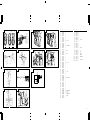
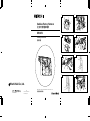
Cordless Rotary Hammer
DH 24DV
505
Code No. C99130131 N
Printed in Japan
1
Hitachi Koki Co., Ltd.
Handling Instructions
Read through carefully and understand these instructions before use.
1
9
7
6
1 2
4
6
8
3
5
7
7
6
5
A
0
B
C
D
H
3
4
8
0
A
C
G
F
I
E
1
2
K
J

Cordless Rotary Hammer
DH 24DV
505
Code No. C99130131 N
Printed in Japan
1
Hitachi Koki Co., Ltd.
Handling Instructions
Read through carefully and understand these instructions before use.
1
9
7
6
1 2
4
6
8
3
5
7
7
6
5
A
0
B
C
D
H
3
4
8
0
A
C
G
F
I
E
1
2
K
J

3
2
24
9 10
12
11
15
14
13
16
L
Z
[
d
[ ]U
PQ
TS
L
(a)M (b)N
(c)O
L
R
W
V
A
B
X
Y
\
B
C
=
]
]
`
a
b
W
C
c
B
C
19
18
17
20
e
i
f
g
h
j
k
l
m
g
21
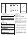
3 mm
11.5 mm
A B C D
1 306-345 1
2 306-340 1
3 323-154 1
4 322-810 1
5 322-811 1
6 322-812 1
7 984-118 1
8 939-547 1
9 305-558 4 D5 × 25
10 323-167 1
11 307-688 1
12 322-815 1
13 690-4DD 1 6904DDPS2L
14 322-819 1
15 322-813 1
16 323-172 1
17
––––––– 1 D2.6
18 878-885 1
19 323-161 1
20 959-156 1 D7.0
21 322-814 1
22 301-677 1
23 316-135 1
24 301-679 1
25 948-310 1
26 322-803 1
27 944-486 1 1AP-20
28 322-804 1
29 322-802 1
30 322-805 1
31 322-808 1
32 322-806 1
33 322-807 1
34 322-801 1
35 322-834 1 I.D.16
36 322-800 1
37 322-799 2
38 323-150 1
39 323-157 1
40 626-VVM 1 626VVC2PS2L
41 323-151 1
42 301-659 1
43 301-660 1
44 301-661 1
45 322-798 1
46 306-990 1
47 323-152 1
48 323-153 1
49 301-663 1
50 323-170 1
51 626-VVM 1 626VVC2PS2L
52 305-812 4 D4 × 16
53 876-796 1 P-22
54 608-DDM 1 608DDC2PS2l
55 360-663 1 DC24V
56 323-156 1
57 982-631 1
A B C D
58 608-DDM 1 608DDC2PS2L
59 308-536 2
60 323-164 1
61 999-090 2
62 323-166 1
63 323-165 1
64 323-158 1
65 302-086 6 D4 × 20
66
––––––– 1
67 323-171 1
68 323-163 1
69 318-247 1
70 319-811 1
71 319-812 1
72 993-963 1 M3 × 12
73
––––––– 1
74 323-159 1
75 949-554 2 M4
76 323-160 1
77 949-215 2 M4 × 8
78 1 319-805 1 EB2420
78 2 323-173 1 EB2430HA
501 323-155 1
502 303-709 1
503
––––––– 1 UC24YFB
504 323-169 1

3
2
24
9 10
12
11
15
14
13
16
L
Z
[
d
[ ]U
PQ
TS
L
(a)M (b)N
(c)O
L
R
W
V
A
B
X
Y
\
B
C
=
]
]
`
a
b
W
C
c
B
C
19
18
17
20
e
i
f
g
h
j
k
l
m
g
21
3 mm
11.5 mm
A B C D
1 306-345 1
2 306-340 1
3 323-154 1
4 322-810 1
5 322-811 1
6 322-812 1
7 984-118 1
8 939-547 1
9 305-558 4 D5 × 25
10 323-167 1
11 307-688 1
12 322-815 1
13 690-4DD 1 6904DDPS2L
14 322-819 1
15 322-813 1
16 323-172 1
17
––––––– 1 D2.6
18 878-885 1
19 323-161 1
20 959-156 1 D7.0
21 322-814 1
22 301-677 1
23 316-135 1
24 301-679 1
25 948-310 1
26 322-803 1
27 944-486 1 1AP-20
28 322-804 1
29 322-802 1
30 322-805 1
31 322-808 1
32 322-806 1
33 322-807 1
34 322-801 1
35 322-834 1 I.D.16
36 322-800 1
37 322-799 2
38 323-150 1
39 323-157 1
40 626-VVM 1 626VVC2PS2L
41 323-151 1
42 301-659 1
43 301-660 1
44 301-661 1
45 322-798 1
46 306-990 1
47 323-152 1
48 323-153 1
49 301-663 1
50 323-170 1
51 626-VVM 1 626VVC2PS2L
52 305-812 4 D4 × 16
53 876-796 1 P-22
54 608-DDM 1 608DDC2PS2l
55 360-663 1 DC24V
56 323-156 1
57 982-631 1
A B C D
58 608-DDM 1 608DDC2PS2L
59 308-536 2
60 323-164 1
61 999-090 2
62 323-166 1
63 323-165 1
64 323-158 1
65 302-086 6 D4 × 20
66
––––––– 1
67 323-171 1
68 323-163 1
69 318-247 1
70 319-811 1
71 319-812 1
72 993-963 1 M3 × 12
73
––––––– 1
74 323-159 1
75 949-554 2 M4
76 323-160 1
77 949-215 2 M4 × 8
78 1 319-805 1 EB2420
78 2 323-173 1 EB2430HA
501 323-155 1
502 303-709 1
503
––––––– 1 UC24YFB
504 323-169 1

4
English
1
2
3
4
5
6
7
8
9
0
A
B
C
D
E
F
G
H
I
J
K
L
M
N
O
P
Q
R
S
T
U
V
W
X
Y
Z
[
\
]
^
a
b
c
d
e
f
g
h
i
j
k
l
m
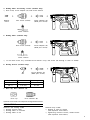
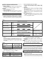
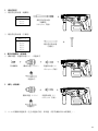
Rechargeable battery
Latch
Guide rail of battery
Push
Housing
Pull out
Insert
Guide rail of housing
Pilot lamp
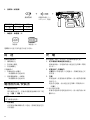
Drill bit
Part of SDS-plus shank
Front cap
Grip
Dust cup
Dust collector (B)
Change lever
“
” mark
“
” mark
“
” mark
“Rotation + Striking” mode
“Rotation only” mode
Push button
Forward rotation
Reverse rotation
Does not rotate
Push the
side
Push the
side
Center position
indication
indication
Diagram seen from the handle side
Drill chuck
Chuck adapter
Depth gauge
Mounting hole
Side handle
Bit
Socket
Taper shank adapter
Cotter
Rest
Shift knob
“POWER“ mode
“SAVE“ mode
Screw
Grip cover
Pull
Carbon brush
Terminal
Pliers
Spring
- driver
Wear limit
“
”
“
”
“
”
-

5
GENERAL OPERATIONAL PRECAUTIONS
1. Keep work area clean. Cluttered areas and benches
invite accidents.
2. Avoid dangerous environment. Don’t expose power
tools and charger to rain. Don’t use power tools
and charger in damp or wet locations. And keep
work area well lit. Never use power tools and
charger near flammable or explosive materials.
Do not use tool and charger in presence of
flammable liquids or gases.
3. The appliance is not intended for use by young
children or infirm persons without supervision.
Young children should be supervised to ensure
that they do not play with the appliance. All visitors
should be kept safe distance from work area.
4. Store idle tools and charger. When not in use,
tools and charger should be stored in dry, high
or locked-up place – out of reach of the children
and infirm persons. Store tools and charger in a
place where the temperature is less than 40°C.
5. Don’t force tool. It will do the job better and safer
at the rate for which it was designed.
6. Use right tool. Don’t force small tool or attachment
to do the job of a heavy duty tool.
7. Wear proper apparel. Do not wear loose clothing
or jewelry. They can be caught in moving parts.
Rubber gloves and non-skid footwears are
recommended when working outdoor.
8. Use eye protection with most tools. Also use face
or dust mask if cutting operation is dusty.
9. Don’t abuse cord. Never carry charger by cord or
yank it to disconnect from receptacle. Keep cord
from heat, oil and sharp edges.
10. Secure work. Use clamps or a vise to hold work.
It’s safer than using your hand and it frees both
hands to operate tool.
11. Don’t overreach. Keep proper footing and balance
at all times.
12. Maintain tools with care. Keep tools sharp at all
times, and clean for best and safest performance.
Follow instructions for lubricating and changing
accessories.
13. When the charger is not in use, or when being
maintained and inspected, disconnect its power
cord from the receptacle.
14. Remove chuck wrenches and wrenches. Form habit
of checking to see that wrenches are removed
from tool before turning it on.
15. Avoid accidental starting. Don’t carry tool with
finger on switch.
16. To avoid danger, always use only the specified charger.
17. Use only genuine HITACHI replacement parts.
18. Do not use power tools for applications other than
those specified in the Handling Instructions.
19. To avoid personal injury, use only the accessories
or attachment recommended in these handling
instructions or in the HITACHI catalog.
20. If the supply cord of this charger is damaged, the
charger must be returned to the HITACHI authorized
service center for the cord to be replaced. Let only
the authorized service center do the repairing. The
Manufacturer will not be responsible for any damages
or injuries caused by repair by the unauthorized
persons or by mishandling of the tool.
21. To ensure the designed operational integrity of
power tools and charger, do not remove installed
covers or screws.
22. Always use the charger at the voltage specified
on the nameplate.
23. Do not touch movable parts or accessories unless
the battery has been removed.
24. Always charge the battery before use.
25. Never use a battery other than that specified. Do
not connect a usual dry cell, a rechargeable battery
other than that specified or a car battery to the
power tool.
26. Do not use any transformer that has a booster.
27. Do not charge the battery from an engine electric
generator or DC power supply.
28. Always charge indoors. Because the charger and
battery heat slightly during charging, charge the
battery in a place not exposed to direct sunlight;
where the humidity is low and the ventilation is
good.
29. When working in a high place, pay attention to
the activities below to make sure there are no
people below.
30. Use the exploded assembly drawing on this
handling instructions only for authorized servicing.
31. If the supply cord is damaged, it must be replaced
by the manufacture or its service agent or a
similarly qualified person in order to avoid a
hazard.
PRECAUTIONS FOR CORDLESS ROTARY
HAMMER
1. Always charge the battery at a temperature of 0
– 40°C.
A temperature of less than 0°C will result in over
charging which is dangerous. The battery cannot
be charged at a temperature higher than 40°C.
The most suitable temperature for charging is that
of 20 – 25°C.
2. Do not use the charger continuously.
When one charging is completed, leave the charger
for about 15 minutes before the next charging of
battery.
3. Do not allow foreign matter to enter the hole for
connecting the rechargeable battery.
4. Never disassemble the rechargeable battery and
charger.
5. Never short-circuit the rechargeable battery. Short-
chircuiting the battery will cause a great electric
current and overheat. It results in burn or damage
to the battery.
6. Do not dispose of the battery in fire.
If the battery is burnt, it may explode.
7. When using this unit continuously, the unit may
overheat, leading to damage in the motor and
switch. Please leave it without using it for
approximately 15 minutes.
8. Do not insert object into the air ventilation slots
of the charger.
Inserting metal objects or inflammables into the
charger air ventilation slots will result in electrical
shock hazard or damaged charger.
9. Using an exhausted battery will damage the
charger.
10. When drilling in wall, floor or ceiling, check for
buried electric power cord, etc.
11. Bring the battery to the shop from which it was
purchased as soon as the post-charging battery
life becomes too short for practical use. Do not
dispose of the exhausted battery.
12. Wear earplugs to protect your ears during
operation.
13. Do not touch the bit during or immediately after
operation. The bit becomes very hot during
operation and could cause serious burns.
14. Always hold the body handle and side handle of
the power tool firmly. Otherwise the counterforce
produced may result in inaccurate and even
dangerous operation.

6
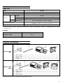
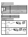
CHARGER
Model UC24YFB
Charging voltage 24 V
Weight 0.6 kg
SPECIFICATIONS
POWER TOOL
DH24DV (BFK)
(HFK)
STANDARD ACCESSORIES
1 Side handle ...................................................................................................................... 1
2 Depth gauge .................................................................................................................... 1
3 Charger .............................................................................................................................. 1
4 Plastic case ....................................................................................................................... 1
Model DH24DV
No-load speed (Save/Power) 0 – 500 / 0 – 1000 / min
Full-load impact rate (Save/Power) 0 – 2200 / 0 – 4500 / min
Concrete 24 mm
Capacity
Drilling Steel 13 mm
Wood 30 mm
Driving Wood screw 6.2 mm (diameter) × 40 mm (length)
Rechargeable battery
EB2420: Ni-Cd 24 V (2.0 Ah 20 cells)
EB2430HA: Ni-MH 24 V (3.0 Ah 20 cells)
Weight 4.0 kg
DH24DV (2BFK)
(2HFK)
1 Side handle ...................................................................................................................... 1
2 Depth gauge .................................................................................................................... 1
3 Charger .............................................................................................................................. 1
4 Plastic case ....................................................................................................................... 1
5 Extra battery .................................................................................................................... 1
Standard accessories are subject to change without notice.
1
2
䡬 Do not use the “SAVE“ mode when boring holes with the wood drill. There is a likelihood that the motor
will burn out.
3
4
1
2
3
4
5

7
Impact Drill Application
Straight Shank Bit
()
OPTIONAL ACCESSORIES (sold separately)
1. Battery (EB2420, EB2430HA)
It may be convenient to prepare some extra batteries.
2. Drilling anchor holes (rotation + striking)
䡬 Drill bit (taper shank) and taper shank adapter
Outer diameter
11.0 mm
12.3 mm
12.7 mm
14.3 mm
14.5 mm
17.5 mm
21.5 mm
䡬 13 mm Hammer Drill chuck and Chuck wrench
Anchor size
W1/4"
W5/16"
W3/8"
Anchor size
W1/4"
W5/16"
W3/8"
W1/2"
W5/8"
3. Anchor setting
䡬 Anchor setting adapter (for rotary hammer)
Anchor setting adapter
(for rotary hammer)
(SDS plus shank)
䡬 Anchor setting adapter (for manual hammer)
Anchor setting adapter
(for manual hammer)
Taper mode Applicable drill bit
Morse taper (No. 1) Drill bit (taper shank) 11.0 – 17.5 mm
Morse taper (No. 2) Drill bit (taper shank) 21.5 mm
A-taper
Taper shank adapter formed A-taper or B-taper
B-taper
is provided as an optional accessory, but drill bit
for it is not provided.
Taper shank adapter
(SDS plus shank)
Drill bit (taper shank)
13 mm Hammer
Drill Chuck
(SDS plus shank)
Cotter
Chuck wrench

8
4. Drilling holes and driving screws (rotation only)
䡬 Drill chuck, chuck adapter (G) and chuck wrench
Special
screw
Drill chuck (13VLR)
Chuck wrench
Chuck adapter (G)
(SDS plus shank)
5. Drilling holes (rotation only)
Drill chuck (13VLA)
Chuck wrench
Chuck adapter (D)
(SDS plus shank)
䡬 13 mm drill chuck ass’y (include chuck wrench ass’y) and chuck (for drilling in steel or wood).
6. Driving Screws (rotation only)
Bit No. Screw Size Length
No. 2 3–5 mm 25 mm
No. 3 5–8 mm 25 mm
7. Dust cup, Dust collector (B)
Dust cup
Dust collector (B)
APPLICATIONS
Rotation and striking mode
䡬 Drilling anchor holes
䡬 Drilling holes in concrete
䡬 Drilling holes in tile
Rotation only mode
䡬 Drilling in steel or wood
(with optional accessories)
䡬 Tightening machine screws, wood screws
(with optional accessories)
Bit
No.
Chuck adapter (D)
(SDS plus shank)
Optional accessories are subject to change without notice.

9
Lights for 0.5 seconds. Does not light for 0.5
seconds. (off for 0.5 seconds)
Lights continuously
Lights for 0.5 seconds. Does not light for 0.5
seconds. (off for 0.5 seconds)
Lights for 0.1 seconds. Does not light for 0.1
seconds. (off for 0.1 seconds)
Lights continuously
Before charging
While charging
Charging complete
Charging impossible
Charging impossible
Blinks
(RED)
Lights
(RED)
Blinks
(RED)
Flikers
(RED)
Lights
(GREEN)
Malfunction in the
battery or the charger
The battery temperature
is high, making
recharging impossible.
Table 1
Indications of the pilot lamp
BATTERY REMOVAL/INSTALLATION
1. Battery removal
Hold the handle tightly and push the battery latches
to remove the battery (see Figs. 1 and 2).
CAUTION
Never short-circuit the battery.
2. Battery installation
Insert the battery aligning both guide rail of battery
and body. Make sure the battery is fixed firmly.
CHARGING
Before using the power tool, charge the battery as follows.
1. Connect the charger’s power cord to a receptacle
When the power cord is connected, the charger’s
pilot lamp will blink in red (At 1-second intervals).
2. Insert the battery into the charger
Insert the battery into the charger as shown in Fig.
3. Make sure the battery is fully seated in the
charger.
3. Charging
When inserting a battery in the charger, charging
will commence and the pilot lamp will light
continuously in red.
When the battery becomes fully recharged, the pilot
lamp will blink in red (At 1-second intervals.) (See
Table 1).
(1) Pilot lamp indication
The indications of the pilot lamp will be as shown
in Table 1, according to the condition of the charger
or the rechargeable battery.
NOTE: The charging time may vary according to ambient
temperature and power source voltage.
4. Disconnect the charger’s power cord from the
receptacle
5. Hold the charger firmly and pull out the battery
NOTE
After operation, pull out batteries from the charger
first, and then keep the batteries properly.
Regarding electric discharge in case of new batteries,
etc.
As the internal chemical substance of new batteries and
batteries that have not been used for an extended period
is not activated, the electric discharge might be low when
using them the first and second time. This is a temporary
phenomenon, and normal time required for recharging
will be restored by recharging the batteries 2–3 times.
How to make the batteries perform longer
(1) Recharge the batteries before they become
completely exhausted.
When you feel that the power of the tool becomes
weaker, stop using the tool and recharge its battery.
If you continue to use the tool and exhaust the
Temperatures at
Battery type which the battery
can be recharged
EB2420 –5°C – 60°C
EB2430HA 0°C – 45°C
(2) Regarding the temperatures of the rechargeable
battery.
The temperatures for rechargeable batteries are as
shown in the table 2, and batteries that have become
hot should be cooled for a while before being
recharged.
Table 2
(3) Regarding recharging time
Depending on the type of the battery, the charging
time will become as shown in Table 3.
Table 3 Charging time (At 20°C)
Battery type Recharging time
EB2420 Approx. 50 min.
EB2430HA Approx. 70 min.

10
electric current, the battery may be damaged and
its life will become shorter.
(2) Avoid recharging at high temperatures.
A rechargeable battery will be hot immediately after
use. If such a battery is recharged immediately after
use, its internal chemical substance will deteriorate,
and the battery life will be shortened. Leave the
battery and recharge it after it has cooled for a
while.
CAUTION
䡬 If the battery has been heated right after operation
(or due to sunlight, etc.), the charger’s pilot lamp
may not light in red. In such a case, first let the
battery cool, then start charging.
䡬 When the pilot lamp flikers in red (at 0.2–second
intervals), check for and take out any foreign objects
in the charger’s battery installation hole. If there are
no foreign objects, it is probable that the battery
or charger is malfunctioning. Take it to your
authorized Service Center.
䡬 Since the built-in micro computer takes about 3
seconds to confirm that the battery being charged
with UC24YFB is taken out, wait for a minimum of
3 seconds before reinserting it to continue charging.
If the battery is reinserted within 3 seconds, the
battery may not be properly charged.
PRIOR TO OPERATION
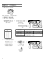
1. Mounting the drill bit (Fig. 4, 5)
CAUTION
To prevent accidents, make sure to turn the switch
off.
NOTE
When using tools such as drill bits, etc., make sure
to use the genuine parts designated by our company.
(1) Clean the shank portion of the drill bit.
(2) Insert the drill bit in a twisting manner into the tool
holder until it latches itself (Fig. 4).
(3) Check the latching by pulling on the drill bit.
(4) To remove the drill bit, fully pull the grip in the
direction of the arrow and pull out the drill bit.
2. Confirm that the battery is mounted correctly
3. Installation of dust cup or dust collector (B) (Optional
accessories) (Fig. 6, Fig. 7)
When using a rotary hammer for upward drilling
operations attach a dust cup or a dust collector (B)
to collect dust or particles for easy operation.
䡬 Installing the dust cup
Use the dust cup by attaching to the drill bit as
shown in Fig. 6.
When using a bit which has big diameter, enlarge
the center hole of the dust cup with this rotary
hammer.
䡬 Installing dust collector (B)
When using dust collector (B), insert dust collector
(B) from the tip of the bit by aligning it to the
groove on the grip (Fig. 7).
CAUTION
䡬 The dust cup and dust collector (B) are for exclusive
use of concrete drilling work. Do not use them for
wood or metal drilling work.
䡬 Insert dust collector (B) completely into the chuck
part of the main unit.
䡬 When turning the rotary hammer on while dust
collector (B) is detached from a concrete surface,
dust collector (B) will rotate together with the drill
bit. Make sure to turn on the switch after pressing
dust cup on the concrete surface. When using dust
collector (B) attached to a drill bit that has more
than 190 mm of overall length, dust collector (B)
cannot touch the concrete surface and will rotate.
Therefore, please use dust collector (B) by attaching
to drill bits which have 166 mm, 160 mm, and 110
mm overall length.
䡬 Dump particles after every two or three holes when
drilling.
䡬 Please replace the drill bit after removing dust
collector (B).
4. Selecting the driver bit
Screw heads or bits will be damaged unless a bit
appropriate for the screw diameter is employed to
drive in the screws.
5. Confirm the direction of bit rotation (Fig. 9)
The bit rotates clockwise (viewed from the rear
side) by pushing the R-side of the push button (Fig.
9-a).
The L-side of the push button is pushed to turn the
bit counterclockwise (Fig. 9-b).
The motor does not rotate if the push button is set
to the center position (Fig. 9-c).
6. Continuous drilling
The number of holes that can be drilled in concrete
after one recharge is shown in Table 4.
Table 4
These data are for the referential values. The number of
holes that can be drilled varies according to the sharpness
of the used bit or the conditions of the concrete being
drilled.
CAUTION
When using this unit continuously, the unit may
overheat, leading to damage in the motor and switch.
Please leave it without using it for approximately
15 minutes.
HOW TO USE
1. Switch operation
䡬 When the switch trigger is depressed, the tool
rotates. When the switch trigger is released, the tool
stops.
Possible continuous
Bit dia. (mm) Depth (mm) drilling number (holes)
EB2420 EB2430HA
6.5 75 110
8.5 45 70
12.5 35 50
14.5
60
30 45
18 20 30
24 7 10

11
䡬 The rotational speed of the rotary hammer can be
controlled by varying the amount that the switch
trigger is pulled. Speed is low when the switch
trigger is pulled slightly and increases as the switch
trigger is pulled more.
䡬 When releasing the switch trigger, the brake will
be applied for immediate stopping.
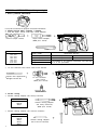
2. Rotation + Striking
Align the “
” mark with the “ ” mark by
rotating the change lever to set the “Rotation +
Striking” mode (Fig. 8).
(1) Mount the drill bit.
(2) Pull the trigger switch after applying the drill bit
tip to the drilling position (Fig. 10).
(3) Pushing the rotary hammer forcibly is not necessary
at all. Pushing slightly so that drill dust comes out
gradually is just sufficient.
CAUTION
When the drill bit touches construction iron bar, the
bit will stop immediately and the rotary hammer
will react to revolve. Therefore please grip the side
handle and handle tightly as shown in Fig. 10.
3. Rotation only
Align the “
” mark with the “ ” mark by rotating
the change lever to set the “Rotation only” mode
(Fig. 8).
To drill a wood or metal material using the optional
drill chuck and chuck adapter, proceed as follows.
Installing drill chuck and chuck adapter: (Fig. 11)
(1) Attach the drill chuck to the chuck adaptor.
(2) The part of the SDS-plus shank is the same as the
drill bit. Therefore, refer to the item of “Mounting
the drill bit” for attaching it.
CAUTION
䡬 Application of force more than necessary will not
only expedite work at all, but will deteriorate the
tip edge of the drill bit and reduce the service life
of the rotary hammer in addition.
䡬 Drill bit may snap off while withdrawing the rotary
hammer from the drilled hole. For withdrawing, it
is important to use a pushing motion.
䡬 Do not attempt to use the rotary hammer in the
rotation and striking mode with the drill chuck and
chuck adapter attached. This would seriously shorten
the service life of every component of the machine.
4. When driving wood screws (Fig. 13)
(1) Selecting a suitable driver bit
Employ plus-head screws, if possible, since the
driver bit easily slips off the heads of slotted-head
screws.
(2) Tightening wood screws
Prior to tightening wood screws, make pilot holes
suitable for them in the wooden board. Apply the
bit to the screw head grooves and gently drive the
screws in the holes.
CAUTION
Exercise care in preparing a pilot hole suitable for
the wood screw taking the hardness of the wood
into consideration. Should the hole be excessively
small or shallow, requiring much power to drive
the screw into it, the thread of the wood screw may
sometimes be damaged.
5. Using depth gauge (Fig. 12)
(1) Loosen the knob on the side handle, and insert the
depth gauge into the mounting hole on the side
handle.
(2) Adjust the depth gauge position according to the
depth of the hole and tighten the knob bolt securely.
6. How to use the drill bit (taper shank) and the taper
shank adapter
(1) Mount the taper shank adapter to the rotary hammer
(Fig. 14).
(2) Mount the drill bit (taper shank) to the taper shank
adapter (Fig. 14).
(3) Turn the switch ON, and drill a hole to prescribed
depth.
(4) To remove the drill bit (taper shank), insert the
cotter into the slot of the taper shank adapter and
strike the head of the cotter with a hammer
supporting on the rest (Fig. 15).
7. Switching between the “SAVE“ and the “POWER“
modes
The hammering force of the hammer can be
increased or decreased to conform with intended
usage, by operating the shift knob as per Fig. 16.
Adjust the force to match the usage intended.
(1) “SAVE“ mode ... decreased hammering force
This can prevent thin drill bits which are less than
5 mm in diameter, from being bent or broken.
(2) “POWER“ mode ... increased hammering force
䡬 This can be used to speedily and efficiently drill
holes when the drill bits which are being used are
greater than 5 mm in diameter.
䡬 This can be used to drill holes into wood or metal.
CAUTION
Do not drill holes in wood with the “SAVE“ mode.
There is a likelihood that the motor will burn out
because it can easily lock up due to the low power.
LUBRICATION
Low viscosity grease is applied to this rotary hammer so
that it can be used for a long period without replacing the
grease. Please contact the nearest service center for
grease replacement when any grease is leaking form
loosened screw.
Further use of the rotary hammer despite the grease
shortage causes damage to reduce the service life.
CAUTION
A specific grease (FG-6A) is used with this machine,
therefore, the normal performance of the machine may
be badly affected by use of different grease. Please be
sure to let one of our service centers to undertake
replacement of the grease.
MAINTENANCE AND INSPECTION
1. Inspecting the tool
Since use of a dull tool will degrade efficiency and
cause possible motor malfunction, sharpen or
replace the tool as soon as abrasion is noted.
2. Inspecting the mounting screws
Regularly inspect all mounting screws and ensure
that they are properly tightened. Should any of the
screws be loose, retighten them immediately. Failure
to do so could result in serious hazard.
3. Maintenance of the motor
The motor unit winding is the very “heart” of the
power tool. Exercise due care to ensure the winding
does not become damaged and/or wet with oil or
water.

12
4. Inspecting the carbon brushes (Fig. 21)
The Motor employs carbon brushes which are
consumable parts. When they become worn to or
near the “wear limit”, it could result in motor trouble.
When an auto-stop carbon brush is equipped, the
motor will stop automatically. At that time, replace
both carbon brushes with new ones which have the
same carbon brush Numbers shown in the figure.
In addition, always keep carbon brushes clean and
ensure that they slide freely within the brush holders.
5. Replacing the carbon brushes
(1) Loosen the screws (2) for the chuck cover, then
remove the chuck cover from the housing (Fig. 17,
Fig. 18).
(2) Pinch the terminals for the carbon brushes with
pliers, then pull them out of the brush holder (Fig.
19).
(3) Pull the springs forward with a Phillips screwdriver,
then remove the carbon brushes (Fig. 20).
(4) Reverse these procedures to install the brushes.
6. Cleaning on the outside
When the power tool is stained, wipe with a soft
dry cloth or a cloth moistened with soapy water.
Do not use chloric solvents, gasoline or paint thinner,
as they melt plastics.
7. Storage
Store the power tool in a place in which the
temperature is less than 40°C and out of reach of
children.
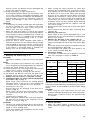
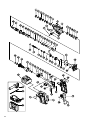
8. Service parts list
A: Item No.
B: Code No.
C: No. Used
D: Remarks
CAUTION
Repair, modification and inspection of Hitachi Power
Tools must be carried out by an Hitachi Authorized
Service Center.
This Parts List will be helpful if presented with the
tool to the Hitachi Authorized Service Center when
requesting repair or other maintenance.
In the operation and maintenance of power tools,
the safety regulations and standards prescribed in
each country must be observed.
MODIFICATIONS
Hitachi Power Tools are constantly being improved
and modified to incorporate the latest technological
advancements.
Accordingly, some parts (i.e. code numbers and/or
design) may be changed without prior notice.
NOTE:
Due to HITACHI’s continuing program of research and
development, the specifications herein are subject to
change without prior notice.

13
°
° °
°
°

14
×
䡬
DH24DV (BFK)
(HFK)
1
2
3
4
DH24DV (2BFK)
(2HFK)
1
2
3
4
5
1
2
3
4
1
2
3
4
5

15
䡬
䡬

16
䡬
䡬
䡬
䡬

17
䡬
䡬
䡬
䡬
䡬

18
䡬
䡬
䡬
EB2420 –5°C – 60°C
EB2430HA 0°C – 45°C
EB2420
EB2430HA

19
䡬
䡬
䡬
䡬
䡬
䡬
䡬
䡬
䡬
䡬
EB2420 EB2430HA
6.5 75 110
8.5 45 70
12.5 35 50
14.5
60
30 45
18 20 30
24 7 10
ページが読み込まれています...
ページが読み込まれています...
ページが読み込まれています...
ページが読み込まれています...
ページが読み込まれています...
ページが読み込まれています...
-
 1
1
-
 2
2
-
 3
3
-
 4
4
-
 5
5
-
 6
6
-
 7
7
-
 8
8
-
 9
9
-
 10
10
-
 11
11
-
 12
12
-
 13
13
-
 14
14
-
 15
15
-
 16
16
-
 17
17
-
 18
18
-
 19
19
-
 20
20
-
 21
21
-
 22
22
-
 23
23
-
 24
24
-
 25
25
-
 26
26


他の言語で
- English: Hikoki DH 24DV User manual
関連論文
その他のドキュメント
-
Hitachi DH24PB2 Handling Instructions Manual
-
-
-
REXON IW140R 取扱説明書
-
-
-
Speakman SA-1203 インストールガイド
-
-
Sony DDM-2802CNU 取扱説明書
-
Inspur IR5280M6 Operation and Maintenance Manual