
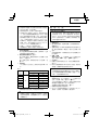
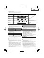
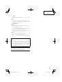
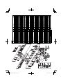
Cordless Rotary Hammer
충전 햄어드릴
Máy khoan búa dùng pin
DH 25DL
•
DH 25DAL
DH 36DL
•
DH 36DAL
Handling instructions Hướng dẫn sử dụng
취급 설명서
DH36DAL
Read through carefully and understand these instructions before use.
본 설명서를 자세히 읽고 내용을 숙지한 뒤 제품을 사용하십시오.
Đọc kỹ và hiểu rõ các hướng dẫn này trước khi sử dụng.

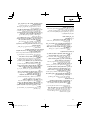
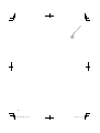
2
12
34
56
78
3
4
1
2
#
8
9
0
1
$
5
7
6
$
%
@
^
!
^
#
*
&
9
0
(
w
e
) q
(
w
e
(a) (b)

3
910
11 12
13 14
15 16
p
f
o
s
r
d
%
^
u
g
i
[ ]
a
(a)
t
(b)
y
r
h
d
%
^
k
j
l
%
^
$
#
z
l
v
c
x
;

4
English
한국어
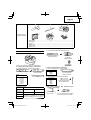
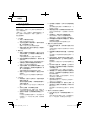
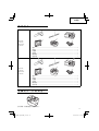
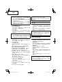
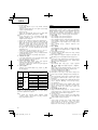
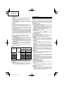
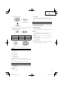
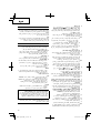
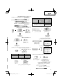
1
Rechargeable battery
충전식 배터리
2
Latch
래치
3
Guide rail of battery
배터리의 가이드 레일
4
Push
누름
5
Battery cover
배터리 커버
6
Terminals
단자
7
Ventilation hole
통풍구
8
Housing
하우징
9
Pull out
잡아당김
0
Insert
삽입
!
Guide rail of housing
하우징의 가이드 레일
@
Pilot lamp
파일럿 램프
#
Drill bit
드릴 비트
$
Part of SDS-plus shank
SDS-플러스 생크의 일부
%
Front cap
프런트 캡
^
Grip
그립
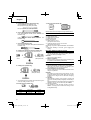
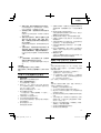
&
Dust
cup
더스트 컵
*
Dust collector (B)
집진기 (B)
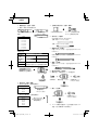
(
Change lever
전환 레버
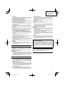
)
"
" mark " " 표시
q
"
" mark " " 표시
w
" " mark " " 표시
e
"
" mark
"
" 표시
r
Push button
푸시 버튼
t
Forward rotation
정회전
y
Reverse rotation
역회전
u
Push the
side
측을 누름
i
Push the
side
측을 누름
o
indication
표시
p
indication
표시
a
Diagram seen from the handle side
핸들쪽에서 바라본 다이어그램
s
Drill chuck
드릴 척
d
Chuck adaptor
척 어댑터
f
Depth gauge
깊이 게이지
g
Mounting hole
장착 구멍
h
Side handle
사이드 핸들
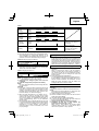
j
Bit
비트
k
Socket
소켓
l
Taper shank adapter
테이퍼 생크 어댑터
;
Cotter
코터
z
Rest
지지대
x
Shift knob
변속 노브
c
"POWER" mode
"파워" 모드
v
"SAVE" mode
"절전" 모드

5
Tiếng Việt
1
Pin sạc
2
Chốt
3
Rãnh trượt của pin
4
Đẩy
5
Nắp pin
6
Đầu cuối
7
Các lỗ thông gió
8
Vỏ máy
9
Kéo ra
0
Chèn
!
Rãnh trượt của vỏ máy
@
Đèn báo
#
Đầu khoan
$
Bộ phận chuôi SDS chữ thập
SDS-plus
%
Nắp trước
^
Kẹp giữ
&
Cốc bụi
*
Bộ thu bụi (B)
(B)
(
Cần chuyển đổi
)
Dấu "
"
“ ”
q
Dấu "
"
“ ”
w
Dấu "
"
“ ”
e
Dấu "
"
“ ”
r
Nút ấn
t
Chuyển động quay về trước
y
Chuyển động quay ngược lại
u
Ấn bên phải
i
Ấn bên trái
o
Ký hiệu bên phải
p
Ký hiệu bên trái
a
Sơ đồ nhìn từ phía tay nắm
s
Đầu cặp mũi khoan
d
Đầu tiếp hợp đầu cặp mũi khoan
f
Thước đo độ sâu
g
Lỗ gắn
h
Tay nắm phụ
j
Mũi khoan
k
Khớp nối
l
Đầu tiếp hợp chuôi côn
;
Chốt giữ
z
Trụ đỡ
x
Núm sang số
c
Chế độ "POWER"
“”
v
Chế độ "SAVE"
“”

English
6
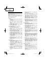
GENERAL SAFETY RULES
WARNING!
Read all instructions
Failure to follow all instructions listed below may result in
electric shock, fi re and/or serious injury.
The term “power tool” in all of the warnings listed below
refers to your mains operated (corded) power tool or battery
operated (cordless) power tool.
SAVE THESE INSTRUCTIONS
1) Work area
a) Keep work area clean and well lit.
Cluttered and dark areas invite accidents.
b) Do not operate power tools in explosive
atmospheres, such as in the presence of
fl ammable liquids, gases or dust.
Power tools create sparks which may ignite the dust
of fumes.
c) Keep children and bystanders away while
operating a power tool.
Distractions can cause you to lose control.
2) Electrical safety
a) Power tool plugs must match the outlet.
Never modify the plug in any way.
Do not use any adapter plugs with earthed
(grounded) power tools.
Unmodifi ed plugs and matching outlets will reduce
risk of electric shock.
b) Avoid body contact with earthed or grounded
surfaces such as pipes, radiators, ranges and
refrigerators.
There is an increased risk of electric shock if your
body is earthed or grounded.
c) Do not expose power tools to rain or wet
conditions.
Water entering a power tool will increase the risk of
electric shock.
d) Do not abuse the cord. Never use the cord for
carrying, pulling or unplugging the power tool.
Keep cord away from heat, oil, sharp edges or
moving parts.
Damaged or entangled cords increase the risk of
electric shock.
e) When operating a power tool outdoors, use an
extension cord suitable for outdoor use.
Use of a cord suitable for outdoor use reduces the
risk of electric shock.
3) Personal safety
a) Stay alert, watch what you are doing and use
common sense when operating a power tool.
Do not use a power tool while you are tired
or under the infl uence of drugs, alcohol or
medication.
A moment of inattention while operating power tools
may result in serious personal injury.
b) Use safety equipment. Always wear eye
protection.
Safety equipment such as dust mask, non-skid
safety shoes, hard hat, or hearing protection used for
appropriate conditions will reduce personal injuries.
c) Avoid accidental starting. Ensure the switch is in
the off position before plugging in.
Carrying power tools with your fi nger on the switch or
plugging in power tools that have the switch on invites
accidents.
d) Remove any adjusting key or wrench before
turning the power tool on.
A wrench or a key left attached to a rotating part of the
power tool may result in personal injury.
e) Do not overreach. Keep proper footing and
balance at all times.
This enables better control of the power tool in
unexpected situations.
f) Dress properly. Do not wear loose clothing or
jewellery. Keep your hair, clothing and gloves
away from moving parts.
Loose clothes, jewellery or long hair can be caught in
moving parts.
g) If devices are provided for the connection of
dust extraction and collection facilities, ensure
these are connected and properly used.
Use of these devices can reduce dust related
hazards.
4) Power tool use and care
a) Do not force the power tool. Use the correct
power tool for your application.
The correct power tool will do the job better and safer
at the rate for which it was designed.
b) Do not use the power tool if the switch does not
turn it on and off .
Any power tool that cannot be controlled with the
switch is dangerous and must be repaired.
c) Disconnect the plug from the power source
before making any adjustments, changing
accessories, or storing power tools.
Such preventive safety measures reduce the risk of
starting the power tool accidentally.
d) Store idle power tools out of the reach of children
and do not allow persons unfamiliar with the
power tool or these instructions to operate the
power tool.
Power tools are dangerous in the hands of untrained
users.
e) Maintain power tools. Check for misalignment or
binding of moving parts, breakage of parts and
any other condition that may aff ect the power
tools’ operation.
If damaged, have the power tool repaired before
use.
Many accidents are caused by poorly maintained
power tools.
f) Keep cutting tools sharp and clean.
Properly maintained cutting tools with sharp cutting
edges are less likely to bind and are easier to control.
g) Use the power tool, accessories and tool bits
etc., in accordance with these instructions and
in the manner intended for the particular type
of power tool, taking into account the working
conditions and the work to be performed.
Use of the power tool for operations diff erent from
intended could result in a hazardous situation.
5) Battery tool use and care
a) Ensure the switch is in the off position before
inserting battery pack.
Inserting the battery pack into power tools that have
the switch on invites accidents.
b) Recharge only with the charger specifi ed by the
manufacturer.
A charger that is suitable for one type of battery pack
may create a risk of fi re when used with another
battery pack.
c) Use power tools only with specifi cally designated
battery packs.
Use of any other battery packs may create a risk of
injury and fi re.

English
7
d) When battery pack is not in use, keep it away
from other metal objects like paper clips, coins,
keys, nails, screws, or other small metal objects
that can make a connection from one terminal to
another.
Shorting the battery terminals together may cause
burns or a fi re.
e) Under abusive conditions, liquid may be ejected
from the battery; avoid contact. If contact
accidentally occurs, fl ush with water. If liquid
contacts eyes, additionally seek medical help.
Liquid ejected from the battery may cause irritation or
burns.
6) Service
a) Have your power tool serviced by a qualifi ed
repair person using only identical replacement
parts.
This will ensure that the safety of the power tool is
maintained.
PRECAUTION
Keep children and infi rm persons away.
When not in use, tools should be stored out of reach of
children and infi rm persons.
CORDLESS ROTARY HAMMER SAFETY
WARNINGS
1. Wear ear protectors.
Exposure to noise can cause hearing loss.
2. Use auxiliary handles supplied with the tool.
Loss of control can cause personal injury.
3. Always charge the battery at a temperature of 0 – 40°C.
A temperature of less than 0°C will result in over charging
which is dangerous. The battery cannot be charged at a
temperature
higher than 40°C.
The most suitable temperature for charging is that of 20 –
25°C.
4. Do not use the charger continuously.
When one charging is completed, leave the charger for
about 15 minutes before the next charging of battery.
5. Do not allow foreign matter to enter the hole for
connecting the rechargeable battery.
6. Never disassemble the rechargeable battery and
charger.
7. Never short-circuit the rechargeable battery. Short-
circuiting the battery will cause a great electric current
and overheat. It results in burn or damage to the battery.
8. Do not dispose of the battery in fi re.
If the battery is burnt,
it may explode.
9. When using this unit continuously, the unit may overheat,
leading to damage in the motor and switch. Please leave
it without using it for approximately 15 minutes.
10. Do not insert object into the air ventilation slots of the
charger.
Inserting metal objects or infl ammables into
the charger
air ventilation slots will result in electrical shock hazard or
damaged charger.
11. Using an exhausted battery will damage the charger.
12. When drilling in wall, fl oor or ceiling, check for buried
electric power cord, etc.
13. Bring the battery to the shop from which it was purchased
as soon
as the post-charging battery life becomes too
short for practical use. Do not dispose of the exhausted
battery.
14. Do not touch the bit during or immediately after operation.
The bit becomes very hot during operation and could
cause serious burns.
15. Always hold the body handle and side handle of the
power tool fi rmly. Otherwise the counterforce produced
may result in inaccurate and even dangerous operation.
16. Wear a dust mask
Do not inhale the harmful dusts generated in drilling or
chiseling operation. The dust can endanger the health of
yourself
and bystandersy.
CAUTION ON LITHIUM-ION BATTERY
To extend the lifetime, the lithium-ion battery equips with the
protection function to stop the output.
In the cases of 1 and 2 described below, when using this
product, even if you are pulling the switch, the motor may
stop. This is not the trouble but the result of protection
function.
1.
When the battery power remaining runs out, the motor
stops.
In such case, charge it up immediately.
2. If the tool is overloaded, the motor may stop. In this
case, release the switch of tool and eliminate causes of
overloading. After that, you can use it again.
Furthermore, please heed the following
warning and caution.
WARNING
In order to prevent any battery leakage, heat generation,
smoke emission, explosion and ignition beforehand, please
be sure to heed the following precautions.
1. Make sure that swarf and dust do not collect on the
battery.
○ During work make sure that swarf and dust do not fall on
the battery.
○ Make sure that any swarf and dust falling on the power
tool during work do not collect on the battery.
○ Do not store an unused battery in a location exposed to
swarf and dust.
○ Before storing a battery, remove any swarf and dust that
may adhere to it and
do not store it together with metal
parts (screws, nails, etc.).
2. Do not pierce battery with a sharp object such as a
nail, strike with a hammer, step on, throw or subject the
battery to severe physical shock.
3. Do not use an apparently damaged or deformed battery.
4. Do
not use the battery in reverse polarity.
5. Do not connect directly to an electrical outlets or car
cigarette lighter sockets.
6. Do not use the battery for a purpose other than those
specifi ed.
7. If the battery charging fails to complete even when a
specifi ed recharging time has elapsed,
immediately stop
further recharging.
8. Do not put or subject the battery to high temperatures or
high pressure such as into a microwave oven, dryer, or
high pressure container.
9. Keep away from fi re immediately when leakage or foul
odor are detected.
10. Do not use in a location where strong static
electricity
generates.
11. If there is battery leakage, foul odor, heat generated,
discolored or deformed, or in any way appears abnormal
during use, recharging or storage, immediately remove it
from the equipment or battery charger, and stop use.
CAUTION
1. If liquid leaking from the battery gets into your eyes, do not
rub your eyes and wash them well with fresh clean water
such as tap water and contact a doctor immediately.
If left untreated, the liquid may cause eye-problems.
2. If liquid leaks onto your skin or clothes, wash well with
clean water such as tap water immediately.
There is a possibility
that this can cause skin irritation.

English
8
3. If you fi nd rust, foul odor, overheating, discolor,
deformation, and/or other irregularities when using the
battery for the fi rst time, do not use and return it to your
supplier or vendor.
WARNING
If an electrically conductive foreign object enters the terminals
of the lithium ion battery, a short-circuit may occur resulting
in the risk of fi re. Please observe the following matters when
storing the battery.
○ Do not place electrically conductive cuttings, nails,
steel wire, copper wire or other wire in the storage
case.
○ Either install the battery in the power tool or store
by securely pressing into the battery cover until the
ventilation holes are concealed to prevent short-
circuits (See Fig. 1).
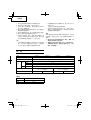
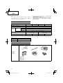
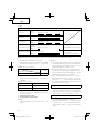
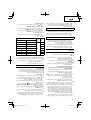
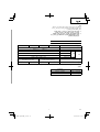
SPECIFICATIONS
POWER TOOL
Model DH25DL DH25DAL DH36DL DH36DAL
No-load speed Save/Power 0 – 550 /min / 0 – 1100 /min
Full-load impact rate Save/Power 0 – 2250 /min / 0 – 4500 /min
Capacity
Drilling
Concrete 26 mm
Steel 13 mm
Wood 30 mm
Driving Wood screw 6.2 mm (diameter) × 40 mm (length)
Rechargeable battery BSL2530: Li-ion 25.2 V (3.0 Ah 14 cells)
BSL3626: Li-ion 36 V
(2.6 Ah 20 cells)
Weight 3.5 kg 3.6 kg 3.9 kg 4.0 kg
○ Do not use the “SAVE” mode when boring holes with the wood drill. There is a likelihood that the motor will burn out.
CHARGER
Model UC36YRL
Charging voltage 25.2 V 36 V
Weight 0.9 kg
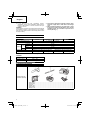
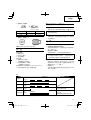
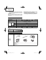
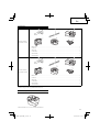
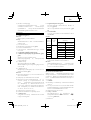
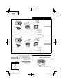
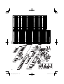
STANDARD ACCESSORIES
DH25DL (2SLRK)
DH25DAL (2SLRK)
3
4
1
2
5
6
1 Side handle ...............................................................................................................................1
2 Depth gauge .............................................................................................................................1
3 Charger .....................................................................................................................................1
4 Plastic case ...............................................................................................................................1
5 Extra battery ..............................................................................................................................1
6 Battery cover .............................................................................................................................1

English
9
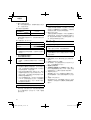
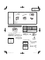
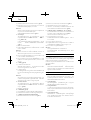
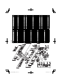
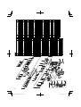
DH36DL (2SLRK)
DH36DAL (2SLRK)
3
4
1
2
5
6
1 Side handle ...............................................................................................................................1
2 Depth gauge .............................................................................................................................1
3 Charger .....................................................................................................................................1
4 Plastic case ...............................................................................................................................1
5 Extra battery ..............................................................................................................................1
6 Battery cover .............................................................................................................................1
Standard accessories are subject to change without notice.
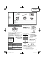
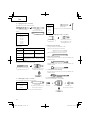
OPTIONAL ACCESSORIES (sold separately)
1. Battery (BSL2530, BSL3626)
It may be convenient to prepare some extra batteries.
2. Drilling anchor holes (rotation + hammering)
○ Drill bit (taper shank) and taper shank adapter
Drill bit (taper shank)
Taper shank adapter
(SDS plus shank)
Cotter
Drill bit
Outer diameter
11.0 mm
12.3 mm
12.7 mm
14.3 mm
14.5 mm
17.5 mm
21.5 mm
Taper shank adapter
Taper mode Applicable drill bit
Morse taper
(No. 1)
Drill bit (taper shank) 11.0 – 17.5 mm
Morse taper
(No. 2)
Drill bit (taper shank) 21.5 mm
A-taper
Taper shank adapter formed A-taper
or B-taper is provided as an optional
accessory, but drill bit for it is not provided.
B-taper
○ 13 mm Hammer
Drill chuck and Chuck wrench
13 mm Hammer
Drill Chuck
(SDS plus shank)
Chuck wrench
Impact Drill Application
Straight Shank Bit
()
3. Anchor setting (rotation + hammering)
○ Anchor setting adapter (for rotary hammer)
Anchor setting adapter
(for rotary hammer)
(SDS plus shank)
Anchor size
W1/4"
W5/16"
W3/8"
○ Anchor setting adapter (for manual hammer)
Anchor setting adapter
(for manual hammer)
Anchor size
W1/4"
W5/16"
W3/8"
W1/2"
W5/8"
4. Bolt placing operation with Chemical Anchor.
(rotation + hammering)
(SDS plus shank)
12.7 mm Chemical Anchor Adapter
19 mm Chemical Anchor Adapter
Standard socket
on the market
()

English
10
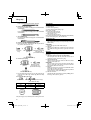
5. Demolishing operation (Hammering only)
(Model DH25DAL and DH36DAL only)
Bull point (Round type) (SDS-plus shank)
Bull point (Square type) (SDS-plus shank)
6. Groove digging and edging (Hammering only)
Cold chisel (SDS-plus shank) (Model DH25DAL and
DH36DAL only)
Cutter (SDS-plus shank) (Model DH25DAL and
DH36DAL only)
7. Grooving (Hammering only)
Grooving chisel (SDS-plus shank) (Model DH25DAL and
DH36DAL only)
8. Drilling holes and driving screws (rotation only)
○ Drill chuck, chuck adapter (G) and chuck wrench
Special
screw
Drill chuck (13VLR)
Chuck adapter (G)
(SDS plus shank)
Chuck wrench
9. Drilling holes (rotation only)
Drill chuck (13VLA)
Chuck adapter (D)
(SDS plus shank)
Chuck wrench
○ 13 mm drill chuck ass’y (include chuck wrench ass’y) and
chuck (for drilling in steel or wood).
10. Driving Screws (rotation only)
Bit No.
Chuck adapter (D)
(SDS plus shank)
Bit No. Screw Size Length
No. 23 – 5 mm 25 mm
No. 35 – 8 mm 25 mm
11. Dust cup, Dust collector (B)
Dust cup
Dust collector (B)
Optional accessories are subject to change without notice.
APPLICATIONS
Rotation and hammering function
○ Drilling anchor holes
○ Drilling holes in concrete
○ Drilling holes in tile
Rotation only function
○ Drilling in steel or wood
(with optional accessories)
○ Tightening machine screws, wood screws
(with optional accessories)
Hammering only function (Model DH25DAL and DH36DAL
only)
○ Light-duty chiselling of concrete, groove
digging and
edging.
BATTERY REMOVAL/INSTALLATION
1. Battery removal
Hold the handle tightly and push the battery latches to
remove the battery (see Figs. 1 and 2).
CAUTION
Never short-circuit the battery.
2. Battery installation
Insert the battery aligning both guide rail of battery and
body. Make sure the battery is fi xed fi rmly.
CHARGING
Before using the power tool, charge the battery as follows.
1. Connect the charger’s power cord to a receptacle
When the power cord is connected, the charger’s pilot
lamp will blink in red (At 1-second intervals).
2. Insert the battery into the charger
Insert the battery fi rmly, until it contacts the bottom of the
charger compartment.
CAUTION
If the battery is inserted in the reverse direction, not
only
recharging will become impossible, but it may also cause
problems in the charger such as deformed recharging
terminal.
3. Charging
When inserting a battery in the charger, charging will
commence and the pilot lamp will light up continuously in
red.
When the battery becomes fully recharged, the pilot lamp
will blink
in red (At 1-second intervals). (See Table 1)
(1) Pilot lamp indication
The indications of the pilot lamp will be as shown in
Table 1, according to the condition of the charger or the
rechargeable battery.

English
11
Table 1
Indications of the lamp
Before
charging
Blinks
(RED)
Lights for 0.5 seconds. Does not light for 0.5 seconds.
(off for 0.5 seconds)
While
charging
Lights
(RED)
Lights continuously
Charging
complete
Blinks
(RED)
Lights for 0.5 seconds. Does not light for 0.5 seconds.
(off for 0.5 seconds)
Charging
impossible
Flickers
(RED)
Lights for 0.1 seconds. Does not light for 0.1 seconds.
(off for 0.1 seconds)
Malfunction in the battery or
the charger
Overheat
standby
Lights
(GREEN)
Lights continuously
Battery overheated.
Unable to charge.
(Charging will commence
when battery cools)
NOTE: When standby for cooling battery, UC36YRL cools the overheated battery by cooling fan.
Regarding electric discharge in case of new batteries,
etc.
As the internal chemical substance of new batteries and
batteries that have not been used for an extended period
is not activated, the electric discharge might be low when
using them the fi rst and second time. This is a temporary
phenomenon, and normal time required for recharging
will be
restored by recharging the batteries 2 – 3 times.
How to make the batteries perform longer.
(1) Recharge the batteries before they become completely
exhausted.
When you feel that the power of the tool becomes
weaker, stop using the tool and recharge its battery. If
you continue to use the tool and exhaust the electric
current, the battery may be damaged and its life will
become
shorter.
(2) Avoid recharging at high temperatures.
A rechargeable battery will be hot immediately after use.
If such a battery is recharged immediately after use, its
internal chemical substance will deteriorate, and the
battery life will be shortened. Leave the battery and
recharge it after it has cooled for a
while.
PRIOR TO OPERATION
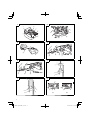
1. Mounting the drill bit (Fig. 4, 5)
CAUTION
To prevent accidents, make sure to turn the switch off .
NOTE:
When using tools such as drill bits, etc., make sure to use
the genuine parts designated by our company.
(1) Clean the shank portion of the drill bit.
(2) Insert the drill bit in a twisting manner into
the tool holder
until it latches itself. (Fig. 4)
(3) Check the latching by pulling on the drill bit.
(4) To remove the drill bit, fully pull the grip in the direction of
the arrow and pull out the drill bit.
2. Confi rm that the battery is mounted correctly
3. Installation of dust cup or dust collector (B)
(Optional accessories) (Fig. 6, Fig. 7)
When using a rotary hammer for upward drilling
operations attach a dust cup or a dust collector (B) to
collect dust or particles for easy operation.
(2) Regarding the temperatures of the rechargeable battery
The temperatures for rechargeable batteries are as
shown in Table 2, and batteries that have become hot
should be cooled for a while before being
recharged.
Table 2 Recharging ranges of batteries
Charger
Rechargeable batteries
UC36YRL
BSL2530, BSL3626 0°C – 50°C
(3) Regarding recharging time
Depending on the type of the battery, the charging time
will become as shown in Table 3.
Table 3 Charging time (At 20°C)
Battery type Recharging time
BSL2530 Approx. 60 min.
BSL3626 Approx. 80 min.
NOTE: The charging time may vary according to ambient
temperature and power source voltage.
4. Disconnect the charger’s power cord from the
receptacle
5. Hold the charger fi rmly and pull out the battery
NOTE:
Be sure to pull out the battery from the charger after use,
and then keep it.
CAUTION
○ If the battery is charged while it is heated because it
has
been left for a long time in a location subject to direct
sunlight or because the battery has just been used, the
pilot lamp of the charger lights up green. In such a case,
fi rst let the battery cool, then start charging.
○ When the pilot lamp fl ickers in
red quickly (at 0.2 –
second intervals), check for and take out any foreign
objects in the charger’s battery installation hole. If there
are no foreign objects, it is probable that the battery or
charger is malfunctioning. Take it to your Authorized
Service Center.
○ Since the built-in micro computer
takes about 3 seconds
to confi rm that the battery being charged with UC36YRL
is taken out, wait for a minimum of 3 seconds before
reinserting it to continue charging. If the battery is
reinserted within 3 seconds, the battery may not be
properly charged.

English
12
○ Installing the dust cup
Use the dust cup by attaching to the drill bit as shown in
Fig. 6.
When using a bit which has big diameter, enlarge the
center hole of the dust cup with this rotary hammer.
○ Installing dust collector (B)
When using dust collector (B),
insert dust collector (B)
from the tip of the bit by aligning it to the groove on the
grip. (Fig. 7).
CAUTION
○ The dust cup and dust collector (B) are for exclusive use
of concrete drilling work. Do not use them for wood or
metal drilling work.
○ Insert dust collector (B
) completely into the chuck part of
the main unit.
○ When turning the rotary hammer on while dust collector
(B) is detached from a concrete surface, dust collector
(B) will rotate together with the drill bit. Make sure to turn
on the switch after pressing dust cup on the concrete
surface. When using dust collector (B) attached to a
drill bit that has more than 190 mm of overall length,
dust collector (B) cannot touch the concrete surface and
will rotate. Therefore, please use dust collector (B) by
attaching to drill bits which have 166 mm, 160 mm, and
110
mm overall length.
○ Dump particles after every two or three holes when
drilling.
○ Please replace the drill bit after removing dust collector
(B).
4. Selecting the driver bit
Screw heads or bits will be damaged unless a bit
appropriate for the screw diameter is employed to drive
in the screws.
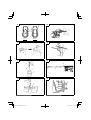
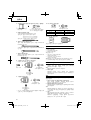
5. Confi rm the direction of bit rotation (Fig. 9)
The bit
rotates clockwise (viewed from the rear side) by
pushing the R-side of the push button. (Fig. 9-a)
The L-side of the push button is pushed to turn the bit
counterclockwise. (Fig. 9-b)
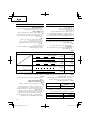
6. Continuous drilling
The number of holes that can be drilled in concrete after
one recharge is shown in Table 4.
Table 4
Bit dia.
(mm)
Depth
(mm)
Possible continuous drilling number
(holes)
DH25DL / DH25DAL DH36DL / DH36DAL
6.5
60
115 160
8.5 70 90
12.5 55 65
14.5 45 55
18 25 40
24 12 16
26 7 8
These data are for the referential values. The number of
holes that can be drilled varies according to the sharpness
of the used bit or the conditions of the concrete being drilled.
CAUTION
When using this unit continuously, the unit may overheat,
leading to damage in the motor
and switch.
Please leave it without using it for approximately 15
minutes.
HOW TO USE
CAUTION on lithium-ion battery
To extend the lifetime, the lithium-ion battery equips with
the protection function to stop the output. Therefore, if the
tool is overloaded, the motor may stop. However, this is
not the trouble but the result of protection function. In this
case, release the switch of tool and eliminate the causes of
overloading.
1. Switch operation
○ When the switch trigger is depressed, the tool rotates.
When the switch trigger is released, the tool stops.
○ The rotational speed of the rotary hammer can be
controlled by varying the amount that the switch trigger
is pulled. Speed is low when the switch trigger is pulled
slightly and
increases as the switch trigger is pulled
more.
○ When releasing the switch trigger, the brake will be
applied for immediate stopping.
2. Rotation + Hammering
Align the “
” mark with the “ ” mark by rotating the
change lever to set the “Rotation + Hammering” function.
(Fig. 8-a, Fig. 8-b)
(1) Mount the drill bit.
(2) Pull the trigger switch after applying the drill bit tip to the
drilling position. (Fig. 10)
(3) Pushing the rotary hammer forcibly is not necessary at
all.
Pushing slightly so that drill dust comes out gradually
is just suffi cient.
CAUTION
When the drill bit touches construction iron bar, the bit
will stop immediately and the rotary hammer will react
to revolve. Therefore please grip the side handle and
handle tightly as shown in Fig. 10.
3. Rotation only
Align the “
” mark with the “ ” mark by rotating the
change lever to set the “Rotation only” function. (Fig. 8-a,
Fig. 8-b)
To drill a wood or metal material using the optional drill
chuck and chuck adapter, proceed as follows. Installing
drill chuck and chuck adapter: (Fig. 11)
(1) Attach the drill chuck to the chuck adaptor.
(2) The part of the SDS-plus shank is the same as the drill
bit. Therefore, refer to the item of “Mounting the drill bit”
for attaching it.
CAUTION
○ Application of force more than necessary will not only
expedite work at all, but will deteriorate the tip edge of the
drill bit
and reduce the service life of the rotary hammer in
addition.
○ Drill bit may snap off while withdrawing the rotary hammer
from the drilled hole. For withdrawing, it is important to
use a pushing motion.
○ Do not attempt to use the rotary hammer in the rotation
and striking mode
with the drill chuck and chuck adapter
attached. This would seriously shorten the service life of
every component of the machine.
4. When driving wood screws (Fig. 13)
(1) Selecting a suitable driver bit
Employ plus-head screws, if possible, since the driver bit
easily slips off the heads of slotted-head screws.
(2) Tightening wood screws
Prior to
tightening wood screws, make pilot holes suitable
for them in the wooden board. Apply the bit to the screw
head grooves and gently drive the screws in the holes.

English
13
CAUTION
Exercise care in preparing a pilot hole suitable for
the wood screw taking the hardness of the wood into
consideration. Should the hole be excessively small or
shallow, requiring much power to drive the screw into
it, the thread of the wood screw may sometimes be
damaged.
5. Hammering only
Align the “
” mark with the “ ” mark by rotating the
change lever to set the “Hammering only” function.
(Fig. 8-a)
(1) Mount the bull point or cold chisel.
6. Using depth gauge (Fig. 12)
(1) Loosen the knob on the side handle, and insert the depth
gauge into the mounting hole on the side handle.
(2) Adjust the depth gauge position
according to the depth of
the hole and tighten the knob bolt securely.
7. How to use the drill bit (taper shank) and the taper
shank adapter
(1) Mount the taper shank adapter to the rotary hammer.
(Fig. 14)
(2) Mount the drill bit (taper shank) to the taper shank
adapter. (Fig. 14)
(3) Turn the switch ON, and drill a hole to prescribed
depth.
(4) To remove the drill bit (taper shank), insert the cotter into
the slot of the taper shank adapter and strike the head of
the cotter with a hammer supporting on the rest. (Fig. 15)
8. Switching between the “SAVE” and the “POWER”
modes
The hammering force of the hammer can be increased or
decreased to conform
with intended usage, by operating
the shift knob as per Fig. 16.
Adjust the force to match the usage intended.
(1) “SAVE” mode ... decreased hammering force
This can prevent thin drill bits which are less than 5 mm in
diameter, from being bent or broken.
(2) “POWER” mode ... increased
hammering force
○ This can be used to speedily and effi ciently drill holes
when the drill bits which are being used are greater than
5 mm in diameter.
○ This can be used to drill holes into wood or metal.
CAUTION
Do not drill holes in wood with the “SAVE” mode.
There
is a likelihood that the motor will burn out because it can
easily lock up due to the low power.
LUBRICATION
Low viscosity grease is applied to this rotary hammer so
that it can be used for a long period without replacing the
grease. Please contact the nearest service center for grease
replacement when any grease is leaking form loosened
screw.
Further use of the rotary hammer despite the grease shortage
causes damage
to reduce the service life.
CAUTION
A specifi c grease (FG-6A) is used with this machine,
therefore, the normal performance of the machine may be
badly aff ected by use of diff erent grease. Please be sure to
let one of our service centers to undertake replacement of
the grease.
MAINTENANCE AND INSPECTION
1. Inspecting the tool
Since use of as dull tool will degrade effi ciency and cause
possible motor malfunction, sharpen or replace the tool
as soon as abrasion is noted.
2. Inspecting the mounting screws
Regularly inspect all mounting screws and ensure that
they are properly tightened. Should any of the screws be
loose, retighten them immediately. Failure
to do so could
result in serious hazard.
3. Maintenance of the motor
The motor unit winding is the very “heart” of the power
tool. Exercise due care to ensure the winding does not
become damaged and/or wet with oil or water.
4. Cleaning on the outside
When the power tool is stained, wipe with a soft dry cloth
or
a cloth moistened with soapy water. Do not use chloric
solvents, gasoline or paint thinner, as they melt plastics.
5. Storage
Store the power tool in a place in which the temperature
is less than 40°C and out of reach of children.
NOTE:
Make sure that the battery is fully charged when stored
for
a long period (3 months or more). The battery with
smaller capacity may not be able to be charged when
used, if stored for a long period.
6. Service parts list
CAUTION
Repair, modifi cation and inspection of Hitachi Power
Tools must be carried out by a Hitachi Authorized Service
Center.
This Parts List
will be helpful if presented with the tool to
the Hitachi Authorized Service Center when requesting
repair or other maintenance.
In the operation and maintenance of power tools, the
safety regulations and standards prescribed in each
country must be observed.
MODIFICATIONS
Hitachi Power Tools are constantly being improved
and modifi ed to
incorporate the latest technological
advancements.
Accordingly, some parts may be changed without prior
notice.
Important notice on the batteries for the Hitachi
cordless power tools
Please always use one of our designated genuine
batteries. We cannot guarantee the safety and
performance of our cordless power tool when used with
batteries other than these designated by us, or when
the battery is disassembled and modifi ed (such as
disassembly and replacement of cells or other internal
parts
).
NOTE
Due to HITACHI’s continuing program of research and
development, the specifi cations herein are subject to
change without prior notice.

14

15
○
○
○
○

16
○
○
○

17
3
4
1
2
5
6
1
2
3
4
5
6
3
4
1
2
5
6
1
2
3
4
5
6

18
○
○
○
○
○
○

19
○
○
○
○
○
○

20
○
○
○
○
○
ページが読み込まれています...
ページが読み込まれています...
ページが読み込まれています...
ページが読み込まれています...
ページが読み込まれています...
ページが読み込まれています...
ページが読み込まれています...
ページが読み込まれています...
ページが読み込まれています...
ページが読み込まれています...
ページが読み込まれています...
ページが読み込まれています...
ページが読み込まれています...
ページが読み込まれています...
ページが読み込まれています...
ページが読み込まれています...
ページが読み込まれています...
ページが読み込まれています...
ページが読み込まれています...
ページが読み込まれています...
ページが読み込まれています...
ページが読み込まれています...
ページが読み込まれています...
ページが読み込まれています...
ページが読み込まれています...
ページが読み込まれています...
ページが読み込まれています...
ページが読み込まれています...
ページが読み込まれています...
ページが読み込まれています...
ページが読み込まれています...
ページが読み込まれています...
ページが読み込まれています...
ページが読み込まれています...
ページが読み込まれています...
ページが読み込まれています...
ページが読み込まれています...
ページが読み込まれています...
ページが読み込まれています...
ページが読み込まれています...
ページが読み込まれています...
ページが読み込まれています...
ページが読み込まれています...
ページが読み込まれています...
-
 1
1
-
 2
2
-
 3
3
-
 4
4
-
 5
5
-
 6
6
-
 7
7
-
 8
8
-
 9
9
-
 10
10
-
 11
11
-
 12
12
-
 13
13
-
 14
14
-
 15
15
-
 16
16
-
 17
17
-
 18
18
-
 19
19
-
 20
20
-
 21
21
-
 22
22
-
 23
23
-
 24
24
-
 25
25
-
 26
26
-
 27
27
-
 28
28
-
 29
29
-
 30
30
-
 31
31
-
 32
32
-
 33
33
-
 34
34
-
 35
35
-
 36
36
-
 37
37
-
 38
38
-
 39
39
-
 40
40
-
 41
41
-
 42
42
-
 43
43
-
 44
44
-
 45
45
-
 46
46
-
 47
47
-
 48
48
-
 49
49
-
 50
50
-
 51
51
-
 52
52
-
 53
53
-
 54
54
-
 55
55
-
 56
56
-
 57
57
-
 58
58
-
 59
59
-
 60
60
-
 61
61
-
 62
62
-
 63
63
-
 64
64


Hitachi DH 25DL Handling Instructions Manual
- タイプ
- Handling Instructions Manual
関連論文
-
Hitachi CS 33EB Handling Instructions Manual
-
-
-
Hikoki DH 14DSL ユーザーマニュアル
-
Hikoki DH 36DBML ユーザーマニュアル
-
Hikoki DH 24DV ユーザーマニュアル
-
-
-
-
その他のドキュメント
-
-
-
Adonit NEO PRO ユーザーマニュアル
-
Inspur IR5280M6 Operation and Maintenance Manual
-
Optoma EH1020 Quick Start Card
-
Optoma Technology Projector EP721 ユーザーマニュアル
-
Optoma X401 クイックスタートガイド
-
Optoma Projector EP721 ユーザーマニュアル
-
Optoma EW615 取扱説明書
-
Optoma EW400 クイックスタートガイド