Hitachi DH24PB2 Handling Instructions Manual
- カテゴリー
- パワーツール
- タイプ
- Handling Instructions Manual

1
Read through carefully and understand these instructions before use.
Rotary Hammer
HANDLING INSTRUCTIONS
DH 24PB2
1
2
4
6
8
3
5
7
1
2
3
4
4
5
6
Hitachi Koki Co., Ltd.
402
Code No. C99128921 N
Printed in Japan

1
Read through carefully and understand these instructions before use.
Rotary Hammer
HANDLING INSTRUCTIONS
DH 24PB2
1
2
4
6
8
3
5
7
1
2
3
4
4
5
6
Hitachi Koki Co., Ltd.
402
Code No. C99128921 N
Printed in Japan

3
2
24
1
2
3
4
5
6
7
8
9
0
A
B
C
D
E
F
G
H
I
J
K
L
M
N
O
P
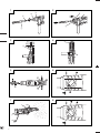
Drill bit
Part of SDS-plus shank
Front cap
Grip
Dust cup
Dust collector (B)
Push button
Change lever
Push button
Drill chuck
Chuck adapter
Chuck adapter (D)
Driver bit
Socket
Side handle
Depth gauge
Mounting hole
Tape shank adapter
Cotter
Rest
Core bit
Core bit shank
Thread
Center pin
Guide plate
Core bit tip
9
10
13
16
14 15
C
D
B
H
J
K
L
M
O
N
K
P
12
11
E
F
G
1
H
I
3
4
17 18
L
3
4

3
2
24
1
2
3
4
5
6
7
8
9
0
A
B
C
D
E
F
G
H
I
J
K
L
M
N
O
P
Drill bit
Part of SDS-plus shank
Front cap
Grip
Dust cup
Dust collector (B)
Push button
Change lever
Push button
Drill chuck
Chuck adapter
Chuck adapter (D)
Driver bit
Socket
Side handle
Depth gauge
Mounting hole
Tape shank adapter
Cotter
Rest
Core bit
Core bit shank
Thread
Center pin
Guide plate
Core bit tip
9
10
13
16
14 15
C
D
B
H
J
K
L
M
O
N
K
P
12
11
E
F
G
1
H
I
3
4
17 18
L
3
4

4

5
嘷

6
嘷
嘷
嘷
嘷

7
嘷

8
嘷
嘷

9
嘷
嘷
嘷
嘷
嘷
嘷
嘷
嘷
嘷
嘷
嘷
嘷

10
嘷
嘷
嘷
嘷
嘷

11

12
GENERAL OPERATIONAL PRECAUTIONS
WARNING! When using electric tools, basic safety
precautions should always be followed to reduce the
risk of fire, electric shock and personal injury, including
the following.
Read all these instructions before operating this product
and save these instructions.
For safe operations:
1. Keep work area clean. Cluttered areas and benches
invite injuries.
2. Consider work area environment. Do not expose
power tools to rain. Do not use power tools in
damp or wet locations. Keep work area well lit.
Do not use power tools where there is risk to cause
fire or explosion.
3. Guard against electric shock. Avoid body contact
with earthed or grounded surfaces (e.g. pipes,
radiators, ranges, refrigerators).
4. Keep children and infirm persons away. Do not let
visitors touch the tool or extension cord. All visitors
should be kept away from work area.
5. Store idle tools. When not in use, tools should be
stored in a dry, high or locked up place, out of reach
of children and infirm persons.
6. Do not force the tool. It will do the job better and
safer at the rate for which it was intended.
7. Use the right tool. Do not force small tools or
attachments to do the job of a heavy duty tool. Do
not use tools for purposes not intended; for example,
do not use circular saw to cut tree limbs or logs.
8. Dress properly. Do not wear loose clothing or
jewelry, they can be caught in moving parts. Rubber
gloves and non-skid footwear are recommended
when working outdoors. Wear protecting hair
covering to contain long hair.
9. Use eye protection. Also use face or dust mask if
the cutting operation is dusty.
10. Connect dust extraction equipment.
If devices are provided for the connection of dust
extraction and collection facilities ensure these are
connected and properly used.
11. Do not abuse the cord. Never carry the tool by the
cord or yank it to disconnect it from the receptacle.
Keep the cord away from heat, oil and sharp edges.
12. Secure work. Use clamps or a vise to hold the work.
It is safer than using your hand and it frees both
hands to operate tool.
13. Do not overreach. Keep proper footing and balance
at all times.
14. Maintain tools with care. Keep cutting tools sharp
and clean for better and safer performance. Follow
instructions for lubrication and changing
accessories. Inspect tool cords periodically and if
damaged, have it repaired by authorized service
center. Inspect extension cords periodically and
replace, if damaged. Keep handles dry, clean, and
free from oil and grease.
15. Disconnect tools. When not in use, before servicing,
and when changing accessories such as blades,
bits and cutters.
16. Remove adjusting keys and wrenches. Form the
habit of checking to see that keys and adjusting
wrenches are removed from the tool before turning
it on.
17. Avoid unintentional starting. Do not carry a plugged-
in tool with a finger on the switch. Ensure switch is
off when plugging in.
18. Use outdoor extension leads. When tool is used
outdoors, use only extension cords intended for
outdoor use.
19. Stay alert. Watch what you are doing. Use common
sense. Do not operate tool when you are tired.
20. Check damaged parts. Before further use of the
tool, a guard or other part that is damaged should
be carefully checked to determine that it will operate
properly and perform its intended function. Check
for alignment of moving parts, free running of
moving parts, breakage of parts, mounting and any
other conditions that may affect its operation. A
guard or other part that is damaged should be
properly repaired or replaced by an authorized
service center unless otherwise indicated in this
handling instructions. Have defective switches
replaced by an authorized service center. Do not
use the tool if the switch does not turn it on and off.
21. Warning
The use of any accessory or attachment, other than
those recommended in this handling instructions,
may present a risk of personal injury.
22. Have your tool repaired by a qualified person.
This electric tool is in accordance with the relevant
safety requirements. Repairs should only be carried
out by qualified persons using original spare parts.
Otherwise this may result in considerable danger
to the user.
PRECAUTIONS ON USING ROTARY HAMMER
1. Wear earplugs to protect your ears during operation.
2. Do not touch the bit during or immediately after
operation. The bit becomes very hot during operation
and could cause serious burns.
3. Before starting to break, chip or drill into a wall, floor
or ceiling, thoroughly confirm that such items as
electric cables or conduits are not buried inside.
4. Always hold the body handle and side handle of the
power tool firmly. Otherwise the counterforce
produced may result in inaccurate and even
dangerous operation.

13
OPTIONAL ACCESSORIES (sold separately)
1. Drilling anchor holes (rotation + hammering)
䡬 Drill bit (Slender shaft)
䡬 Drill bit (Taper shank) and taper shank adapter
Drill bit (slender shaft)
Outer diameter Effective length Overall length
3.4 mm
45 mm 90 mm
3.5 mm
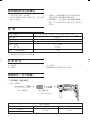
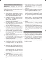
SPECIFICATIONS
Voltage (by areas)* (110V, 115V, 120V, 127V, 220V, 230V, 240V)
Power Input 720W*
No-load speed 0 – 1050/min.
Full-load impact rate 0 – 4600/min.
Capacity: concrete 3.4 – 24 mm
steel 13 mm
wood 32 mm
Weight (without cord and side handle) 2.4 kg
*Be sure to check the nameplate on product as it is subject to change by areas.
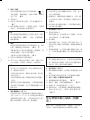
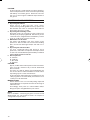
STANDARD ACCESSORIES
(1) Plastic case .................................................................. 1
(2) Side handle ................................................................. 1
(3) Depth gauge ............................................................... 1
Standard accessories are subject to change without
notice.
Adapter for slender shaft
(SDS-plus shank)
Drill bit (Slender shaft)
Drill bit (Taper shank)
Taper shank adapter
(SDS-plus shank)
Cotter
Outer diameter
11.0 mm
12.3 mm
12.7 mm
14.3 mm
14.5 mm
17.5 mm
21.5 mm
Taper mode Applicable drill bit
Morse taper (No.1) Drill bit (taper shank) 11.0 ~ 17.5 mm
Morse taper (No.2) Drill bit (taper shank) 21.5 mm
A-taper Taper shank adapter formed A-taper or B-taper
is provided as an optional accessory, but the
B-taper
drill bit for it is not provided.

14
( )
Straight shank bit
for impact drill
䡬 13 mm Hammer drill chuck
For drilling operations when using a straight shank bit for impact drilling with a rotary hammer.
13 mm Hammer drill chuck
(SDS-plus shank)
Chuck wrench
䡬 Anchor setting adapter (for manual hammer)
Anchor setting adapter
(for manual hammer)
Anchor setting adapter (SDS-plus shank)
(for rotary hammer)
Overall length: 160, 260 mm
Anchor size
W1/4”
W5/16”
W3/8”
Anchor size
W1/4”
W5/16”
W3/8”
W1/2”
W5/8”
3. Large hole boring (rotation + hammering)
䡬 Center pin, core bit, core bit shank and guide plate
(Guide plate) Center pin Core bit Core bit shank
(SDS-plus shank)
Center pin Core bit (outer diameter) Core bit shank
–
25 mm
29 mm
(A)
32 mm Core bit shank (A)
Center pin (A) 35 mm
38 mm
45 mm
Center pin (B) (B)
50 mm
Core bit shank (B)
Do not use core bits with With guide plate
outer diameter of 25 mm (The guide plate is not equipped with core bits
and 29 mm. with outer diameter of 25 mm and 29 mm.)
2. Anchor setting (rotation+hammering)
䡬 Anchor setting adapter (for rotary hammer)

15
4. Crushing operation (rotation + hammering)
Bull point (Round type only)
(SDS-plus shank)
5. Bolt placing operation with Chemical Anchor (rotation + hammering)
(SDS-plus shank)
12.7 mm Chemical Anchor Adapter
19 mm Chemical Anchor Adapter
Standard socket
on the market
6. Drilling holes and driving screws (rotation only)
䡬 Drill chuck, chuck adapter (G), special screw and chuck wrench
Chuck adapter (G)
(SDS-plus shank)
Chuck wrench
Drill chuck (13VLRB
–D
)Special screw
( )

16
7. Drilling holes (rotation only)
Chuck adapter (D)
(SDS-Plus shank)
Chuck wrench
䡬 13 mm drill chuck ass’y (includes chuck wrench) and chuck (for drilling in steel or wood)
8. Driving Screws (rotation only)
Chuck adapter (D)
(SDS-plus shank)
Bit No. Screw Size Length
No. 2 3 – 5 mm 25 mm
No. 3 6 – 8 mm 25 mm
9. Dust cup, Dust collector (B)
Optional accessories are subject to change without notice.
Dust cup
Dust collector (B)
10. Hammer grease A
500 g (in a can)
70 g (in a green tube)
30 g (in a green tube)
Bit No.
Drill chuck (13VLD–D)

17
APPLICATIONS
Rotation and hammering function
䡬 Drilling anchor holes
䡬 Drilling holes in concrete
䡬 Drilling holes in tile
Rotation only function
䡬 Drilling in steel or wood
(with optional accessories)
䡬 Tightening machine screws, wood screws
(with optional accessories)
PRIOR TO OPERATION
1. Power source
Ensure that the power source to be utilized conforms
to the power requirements specified on the product
nameplate.
2. Power switch
Ensure that the power switch is in the OFF position.
If the plug is connected to a power receptacle while
the power switch is in the ON position, the power
tool will start operating immediately, which could
cause a serious accident.
3. Extension cord
When the work area is removed from the power
source, use an extension cord of sufficient thickness
and rated capacity. The extension cord should be kept
as short as practicable.
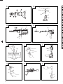
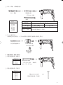
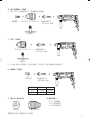
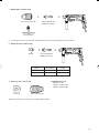
4. Mounting the drill bit (Fig. 1)
CAUTION:
To prevent accidents, make sure to turn the switch
off and disconnect the plug from the receptacle.
NOTE:
When using tools such as bull points, drill bits, etc.,
make sure to use the genuine parts designated by
our company.
(1) Clean the shank portion of the drill bit.
(2) Insert the drill bit in a twisting manner into the tool
holder until it latches itself. (Fig. 1)
(3) Check the latching by pulling on the drill bit.
(4) To remove the drill bit, fully pull the grip in the
direction of the arrow and pull out the drill bit. (Fig. 2)
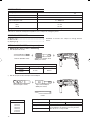
5. Installation of dust cup or dust collector (B)
(Optional accessories) (Fig. 3, Fig. 4)
When using a hammer drill for upward drilling
operations attach a dust cup or dust collector (B) to
collect dust or particles for easy operation.
䡬 Installing the dust cup
Use the dust cup by attaching to the drill bit as shown
in Fig. 3.
When using a bit which has big diameter, enlarge the
center hole of the dust cup with this hammer drill.
䡬 Installing dust collector (B)
When using dust collector (B), insert dust collector
(B) from the tip of the bit by aligning it to the groove
on the grip. (Fig. 4)
CAUTION:
䡬 The dust cup and dust collector (B) are for exclusive
use of concrete drilling work. Do not use them for
wood or metal drilling work.
䡬 Insert dust collector (B) completely into the chuck
part of the main unit.
䡬 When turning the hammer drill on while dust collector
(B) is detached from a concrete surface, dust collector
(B) will rotate together with the drill bit. Make sure to
turn on the switch after pressing the dust cup on the
concrete surface. (When using dust collector (B)
attached to a drill bit that has more than 190 mm of
overall length, dust collector (B) cannot touch the
concrete surface and will rotate. Therefore please
use dust collector (B) by attaching to drill bits which
have 166 mm, 160 mm, and 110 mm overall length.
䡬 Dump particles after every two or three holes when
drilling.
䡬 Please replace the drill bit after removing dust
collector (B).
6. Selecting the driver bit
Screw heads or bits will be damaged unless a bit
appropriate for the screw diameter is employed to
drive in the screws.
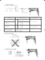
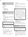
7. Confirm the direction of bit rotation (Fig. 5)
The bit rotates clockwise (viewed from the rear side)
by pushing the R-side of the push button. The L-side
of the push button is pushed to turn the bit
counterclockwise.
HOW TO USE
CAUTION:
To prevent accidents, make sure to turn the switch
off and disconnect the plug from the receptacle when
the drill bits and other various parts are installed or
removed. The power switch should also be turned
off during a work break and after work.
1. Switch operation
The rotation speed of the drill bit can be controlled
steplessly by varying the amount that the trigger
switch is pulled. Speed is low when the trigger
switch is pulled slightly and increases as the switch
is pulled more. Continuous operation may be attained
by pulling the trigger switch and depressing the
stopper. To turn the switch OFF, pull the trigger switch
again to disengage the stopper, and release the trigger
switch to its original position.
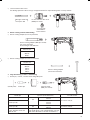
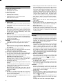
2. Rotation + hammering
This rotary hammer can be set to rotation and
hammering mode by pressing the push button and
turning the change lever to the
mark. (Fig. 6)
(1) Mount the drill bit.
(2) Pull the trigger switch after applying the drill bit tip to
the drilling position. (Fig. 7)
(3) Pushing the rotary hammer forcibly is not necessary
at all. Pushing slightly so that drill dust comes out
gradually is sufficient.
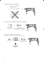
CAUTION:
When the drill bit touches construction iron bar, the
bit will stop immediately and the rotary hammer will
react to revolve. Therefore grip the side handle and
handle tightly as shown in Fig. 7.
3. Rotation only
This rotary hammer can be set to rotation only mode
by pressing the push button and turning the change
lever to the
mark. (Fig. 8)
To drill wood or metal material using the drill chuck
and chuck adapter (optional accessories), proceed as
follows.
Installing drill chuck and chuck adapter: (Fig. 9)

18
(1) Attach the drill chuck to the chuck adapter.
(2) The part of the SDS-plus shank is the same as the
drill bit. Therefore, refer to the item of “Mounting the
drill bit” for attaching it.
CAUTION:
䡬 Application of force more than necessary will not
only expedite the work, but will deteriorate the tip
edge of the drill bit and reduce the service life of the
rotary hammer in addition.
䡬 Drill bits may snap off while withdrawing the rotary
hammer from the drilled hole. For withdrawing, it is
important to use a pushing motion.
䡬 Do not attempt to drill anchor holes or holes in
concrete with the machine set in the rotation only
function.
䡬 Do not attempt to use the rotary hammer in the
rotation and hammering function with the drill chuck
and chuck adapter attached. This would seriously
shorten the service life of every component of the
machine.
4. When driving machine screws (Fig. 10)
First, insert the bit into the socket in the end of chuck
adapter (D).
Next, mount chuck adapter (D) on the main unit
using procedures described in 4 (1), (2), (3), (4), put
the tip of the bit in the slots in the head of the screw,
grasp the main unit and tighten the screw.
CAUTION:
䡬 Exercise care not to excessively prolong driving time,
otherwise, the screws may be damaged by excessive
force.
䡬 Apply the rotary hammer perpendicularly to the screw
head when driving the screw; otherwise, the screw
head or bit will be damaged, or driving force will not
be fully transferred to the screw.
䡬 Do not attempt to use the rotary hammer in the
rotation and hammering function with the chuck
adapter and bit attached.
5. When driving wood screws (Fig. 10)
(1) Selecting a suitable driver bit
Employ plus-head screws, if possible, since the driver
bit easily slips off the heads of minus-head screws.
(2) Driving in wood screws
䡬 Prior to driving in wood screws, make pilot holes
suitable for them in the wooden board. Apply the bit
to the screw head grooves and gently drive the screws
into the holes.
䡬 After rotating the rotary hammer at low speed for a
while until the wood screw is partly driven into the
wood, squeeze the trigger more strongly to obtain
the optimum driving force.
CAUTION:
Exercise care in preparing a pilot hole suitable for the
wood screw taking the hardness of the wood into
consideration. Should the hole be excessively small
or shallow, requiring much power to drive the screw
into it, the thread of the wood screw may sometimes
be damaged.
6. Using depth gauge (Fig. 11)
(1) Loosen the knob on the side handle, and insert the
depth gauge into the mounting hole on the side
handle.
(2) Adjust the depth gauge position according to the
depth of the hole and tighten the knob securely.
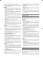
7. How to use the drill bit (taper shank) and the taper
shank adapter
(1) Mount the taper shank adapter to the rotary hammer.
(Fig. 12)
(2) Mount the drill bit (taper shank) to the taper shank
adapter. (Fig. 12)
(3) Turn the switch ON, and drill a hole in prescribed
depth.
(4) To remove the drill bit (taper shank), insert the cotter
into the slot of the taper shank adapter and strike the
head of the cotter with a hammer supporting on a
rests. (Fig. 13)
HOW TO USE THE CORE BIT
(FOR LIGHT LOAD)
When boring penetrating large holes use the core bit (for
light loads). At that time use with the center pin and the
core bit shank provided as optional accessories.
1. Mounting
CAUTION:
Be sure to turn power OFF and disconnect the plug
from the receptacle.
(1) Mount the core bit to the core bit shank. (Fig. 14)
Lubricate the thread of the core bit shank to facilitate
disassembly.
(2) Mount the core bit to the rotary hammer. (Fig. 15)
(3) Insert the center pin into the guide plate until it stops.
(4) Engage the guide plate with the core bit, and turn the
guide plate to the left or the right so that it does not
fall even if it faces downward. (Fig. 16)
2. How to bore (Fig. 17)
(1) Connect the plug to the power source.
(2) A spring is installed in the center pin.
Push it lightly to the wall or the floor straight.
Connect the core bit tip flush to the surface and start
operating.
(3) When boring about 5 mm in depth the position of the
hole will be established. Bore after that removing the
center pin and the guide plate from core bit.
(4) Application of excessive force will not only expedite
the work, but will deteriorate the tip edge of the drill
bit, resulting in reduced service life of the hammer
drill.
CAUTION:
When removing the center pin and the guide plate,
turn OFF the switch and disconnect the plug from the
receptacle.
3. Dismounting (Fig. 18)
Remove the core bit shank from the rotary hammer
and strike the head of the core bit shank strongly two
or three times with a hammer holding the core bit,
then the thread becomes loose and the core bit can
be removed.
LUBRICATION
Low viscosity grease is applied to this rotary hammer so
that it can be used for a long period without replacing
the grease. Please contact the nearest service center for
grease replacement when any grease is leaking from
loosened screw.
Further use of the rotary hammer with lock off grease
will cause the machine to seize up reduce the service life.

19
CAUTION:
A special grease is used with this machine, therefore,
the normal performance of the machine may be badly
affected by use of other grease. Please be sure to let
one of our service agents undertake replacement of
the grease.
MAINTENANCE AND INSPECTION
1. Inspecting the drill bits
Since use of a dull tool will cause motor
malfunctioning and degraded efficiency, replace the
drill bit with new ones or resharpen them without
delay when abrasion is noted.
2. Inspecting the mounting screws
Regularly inspect all mounting screws and ensure
that they are properly tightened. Should any of the
screws be loose, retighten them immediately. Failure
to do so could result in serious hazard.
3. Maintenance of the motor
The motor unit winding is the very “heart” of the
power tool. Exercise due care to ensure the winding
does not become damaged and/or wet with oil or
water.
4. Inspecting the carbon brushes
For your continued safety and electrical shock
protection, carbon brush inspection and replacement
on this tool should ONLY be performed by a HITACHI
AUTHORIZED SERVICE CENTER.
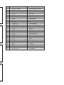
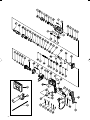
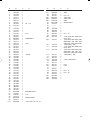
5. Service parts list
A : Item No.
B : Code No.
C : No. Used
D : Remarks
CAUTION:
Repair, modification and inspection of Hitachi Power
Tools must be carried out by a Hitachi Authorized
Service Center.
This Parts List will be helpful if presented with the
tool to the Hitachi Authorized Service Center when
requesting repair or other maintenance.
In the operation and maintenance of power tools, the
safety regulations and standards prescribed in each
country must be observed.
MODIFICATIONS:
Hitachi Power Tools are constantly being improved
and modified to incorporate the latest technological
advancements.
Accordingly, some parts (i.e. code numbers and/or
design) may be changed without prior notice.
NOTE:
Due to HITACHI’s continuing program of research and
development, the specifications herein are subject to
change without prior notice.
ページが読み込まれています...
ページが読み込まれています...
ページが読み込まれています...
ページが読み込まれています...
ページが読み込まれています...
ページが読み込まれています...
-
 1
1
-
 2
2
-
 3
3
-
 4
4
-
 5
5
-
 6
6
-
 7
7
-
 8
8
-
 9
9
-
 10
10
-
 11
11
-
 12
12
-
 13
13
-
 14
14
-
 15
15
-
 16
16
-
 17
17
-
 18
18
-
 19
19
-
 20
20
-
 21
21
-
 22
22
-
 23
23
-
 24
24
-
 25
25
-
 26
26


Hitachi DH24PB2 Handling Instructions Manual
- カテゴリー
- パワーツール
- タイプ
- Handling Instructions Manual
他の言語で
- English: Hitachi DH24PB2