
Cordless Impact Wrench
WR 12DAF
Handling instructions
Read through carefully and understand these instructions before use.

1
2
8
43
1
7
1
6
1
2
1
3
4
5
2
1
7
8
6
8
F
(A)
(B)
5
4
3
2
1
5
C
A
B9
9
D
E
A
6
7
9
0
A

32
13
1211
I
14
R
MM
L
L
K
J
I
10
F
H
9
G

3
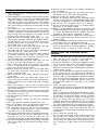
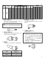
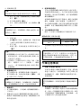
12 V Rechargeable battery
Latch
Handle
Insert
Pull out
Insert
Pilot lamp
Hole for connecting the rechargeable battery
Hexagonal socket
Groove
Anvil
Pin
Ring
Hole
Plunger
Hook
Loosen
Spring
Larger diameter faces away
Protruded section
Groove
Push button
Push
1
2
3
4
5
6
7
8
9
0
A
B
C
D
E
F
G
H
I
J
K
L
M

4
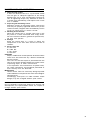
GENERAL OPERATIONAL PRECAUTIONS
1. Keep work area clean. Cluttered areas and benches
invite accidents.
2. Avoid dangerous environment. Don’t expose power
tools and charger to rain. Don’t use power tools and
charger in damp or wet locations. And keep work
area well lit. Never use power tools and charger
near flammable or explosive materials. Do not use
tool and charger in presence of flammable liquids
or gases.
3. The appliance is not intended for use by young
children or infirm persons without supervision. Young
children should be supervised to ensure that they
do not play with the appliance. All visitors should
be kept safe distance from work area.
4. Store idle tools and charger. When not in use, tools
and charger should be stored in dry, high or locked-
up place-out of reach of the children and infirm
persons. Store tools and charger in a place where
the temperature is less than 40°C.
5. Don’t force tool. It will do the job better and safer
at the rate for which it was designed.
6. Use right tool. Don’t force small tool or attachment
to do the job of a heavy duty tool.
7. Wear proper apparel. Do not wear loose clothing
or jewelry. They can be caught in moving parts.
Rubber gloves and non-skid footwears are
recommended when working outdoor.
8. Use eye protection with most tools. Also use face
or dust mask if cutting operation is dusty.
9. Don’t abuse cord. Never carry charger by cord or
yank it to disconnect from receptacle. Keep cord
from heat, oil and sharp edges.
10. Secure work. Use clamps or a vise to hold work.
It’s safer than using your hand and it frees both
hands to operate tool.
11. Don’t overreach. Keep proper footing and balance
at all times.
12. Maintain tools with care. Keep tools sharp at all
times, and clean for best and safest performance.
Follow instructions for lubricating and changing
accessories.
13. When the charger is not in use, or when being
maintained and inspected, disconnect its power cord
from the receptacle.
14. Remove chuck wrenches and wrenches. Form habit
of checking to see that wrenches are removed from
tool before turning it on.
15. Avoid accidental starting. Don’t carry tool with finger
on switch.
16. To avoid danger, always use only the specified
charger.
17. Use only genuine HITACHI replacement parts.
18. Do not use power tools for applications other than
those specified in the Handling Instructions.
19. To avoid personal injury, use only the accessories
or attachment recommended in these handling
instructions or in the HITACHI catalog.
20. Let only the authorized service center do the repairing.
The Manufacturer will not be responsible for any
damages or injuries caused by repair by the
unauthorized persons or by mishandling of the tool.
21. To ensure the designed operational integrity of power
tools and charger, do not remove installed covers
or screws.
22. Always use the charger at the voltage specified on
the nameplate.
23. Do not touch movable parts or accessories unless
the power source has been disconnected.
24. Always charge the battery before use.
25. Never use a battery other than that specified. Do not
connect a usual dry cell, a rechargeable battery other
than that specified or a car battery to the power tool.
26. Do not use any transformer that has a booster.
27. Do not charge the battery from an engine electric
generator or DC power supply.
28. Always charge indoors. Because the charger and
battery heat slightly during charging, charge the battery
in a place not exposed to direct sunlight; where the
humidity is low and the ventilation is good.
29. Before starting to work in a high place, pay attention
to the activities below to make sure there are no
people below.
30. Use the exploded assembly drawing on this handling
instructions only for authorized servicing.
31. If the supply cord is damaged, it must be replaced
by the manufacture or its service agent or a similary
qualified person in order to avoid a hazard.
PRECAUTIONS FOR CORDLESS IMPACT
WRENCH
1. This is a portable tool for tightening and loosening
bolts and nuts. Use it only for these operation.
2. Use the earplugs if using for a long time.
3. One-hand operation is extremely dangerous; hold
the unit firmly with both hands when operating.
4. Check that the socket is not cracked or broken.
Broken or cracked sockets are dangerous. Check the
socket before using it.
5. Secure the socket with the socket pin and the ring.
If the socket pin or ring securing the socket is
damaged, the socket may come off from the impact
wrench, which is quite dangerous. Do not use socket
pins or rings that are deformed, worn out, cracked,
or in any other way damaged. Always make sure
to install the socket pin and ring in the correct
position.
6. Check the tightening torque.
The appropriate torque for tightening a bolt depends
on the material the bolt is made of, its dimensions,
grade, etc.
Also, the tightening torque generated by this impact
wrench depends on the materials and dimensions
of the bolt, how long the impact wrench is applied
for the way in which the socket is installed, etc.
Also the torque when the battery has just been
charged and when it is about to run out are slightly
different. Use a torque wrench to check that the bolt
has been tightened with the appropriate torque.
7. Stop the impact wrench before switching the direction
of rotation. Always release the switch and wait for
impact wrench to stop before switching the direction
of rotation.
8. Never touch the turning part.
Do not allow the turning socket section to get near
your hands or any other part of your body. You
could be cut or caught in the socket. Also, be careful
not to touch the socket after using continuously it
for a long time. It gets quite hot and could burn
you.

5
9. Never let the impact wrench turn without a load
when using the universal joint.
If the socket turns without being connected to a
load, the universal joint causes the socket to turn
wildly.
You could get hurt or the movement of the socket
could shake the impact wrench so much as to make
you drop it.
10. Always charge the battery at a temperature of 0 –
40°C. A temperature of less than 0°C will result in
over charging which is dangerous. The battery cannot
be charged at a temperature higher than 40°C. The
most suitable temperature for charging is that of
20 – 25°C.
11. When one charging is completed, leave the charger
at least 15 minutes before the next charging of
battery.
Do not charge more than two batteries consecutively.
12. Do not allow foreign matter to enter the hole for
connecting the rechargeable battery.
13. Never disassemble the rechargeable battery and
charger.
14. Never short-circuit the rechargeable battery. Short-
circuiting the battery will cause a great electric
current and overheat. It results in burn or damage
to the battery.
15. Do not dispose of the battery in fire.
If the battery is burnt, it may explode.
16. Do not insert object into the air ventilation slots
of the charger.
Inserting metal objects or inflammables into the
charger air ventilation slots will result in electrical
shock hazard or damaged charger.
17. Bring the battery to the shop from which it was
purchased as soon as the post-charging battery life
becomes too short for practical use. Do not dispose
of the exhausted battery.
18. Using an exhausted battery will damage the charger.
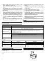
MODEL
WR12DAF: with charger and case
SPECIFICATIONS
POWER TOOL
CHARGER
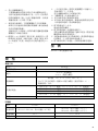
Model UC12SD UC14YFA
Charging time
EB1212S, EB1214L:
EB1220BL: Approx. 50 min. (at 20°C)
Approx. 60 min. (at 20°C)
EB1226HL: Approx. 60 min. (at 20°C)
Charging voltage 12 V 7.2 - 14.4 V
Weight 1.4 kg 0.6 kg
Model WR12DAF
No-load speed 0 – 2200/min
Capacity
M6 – M14 (Ordinary bolt)
M6 – M10 (High tension bolt)
Tightening torque
Maximum 110 N·m {1120 kgf·cm}
Tightening is M12 high tension bolt (strength grade 12.9), when fully
charged at 20°C temp.
Tightening time: 3 sec.
Rechargeable battery
EB1212S: Ni-Cd battery, 12 V (1.2 Ah, 10 cells)
EB1214L: Ni-Cd battery, 12 V (1.4 Ah, 10 cells)
EB1220BL: Ni-Cd battery, 12 V (2.0 Ah, 10 cells)
EB1226HL: Ni-MH battery, 12 V (2.6 Ah, 10 cells)
Weight 1.6 kg
STANDARD ACCESSORIES
1. Charger (UC12SD or UC14YFA) ............................ 1
2. Plastic case ................................................................ 1
Standard accessories are subject to change without
notice.
OPTIONAL ACCESSORIES (sold separately)
1. Battery (EB1212S, EB1214L, EB1220BL, EB1226HL)

6
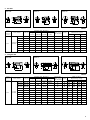
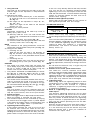
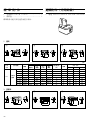
2. Sockets
Table 1
Code No.
High ISO ISO Inch
Form
tension
(ordinary)
(small) bolts L L1 øF
10 mm 944291 M6 10 B 40 8 18
12 mm 873632 M8 W5/16" 12 B 40 8 20
13 mm 873539 M8 13 B 40 9 25
12.7
14 mm 873540 M10 14 B 40 9 25
17 mm 873536 M10 M12 W3/8" 17 C 32 8 28
19 mm 873624 M12 M14 W7/16" 19 C 34 9 28
21 mm 873626 W1/2" 21 D 36 10 32
22 mm 873627 M12 M14 M16 22 D 40 14 35
Main Socket
Dimensions (mm)
H
S
L1
L2
L
ØF
H S
L
L1
ØF
Form B Form C Form D
Square
head drive
dimensions
S (mm)
Part Name
Suitable Bolt Diameter
Hexagonal
width across
flats H (mm)
Hexagonal
Socket
Form B Form C
Form D
H S
L1
L2
L
ØF
H S
L
L1
ØF
H S
L
L1
ØF
H
S
L1
L2
L
ØF
3. Long Socket
Table 2
Code No.
High ISO ISO Inch
Form
tension
(ordinary)
(small) bolts L L1 L2 øF
12 mm 955138 M8 W5/16" 12 B 52 20 34 20
13 mm 955139 M8 13 B 52 20 34 21.5
14 mm 955140 M10 14 B 52 20 34 22
17 mm 955141 M10 M12 W3/8" 17 B 52 24 34 25
17 mm 955149 M10 M12 W3/8" 17 B 75 24 57 25
12.7
Socket
19 mm 955142 M12 M14 W7/16" 19 B 52 24 34 28
19 mm 955150 M12 M14 W7/16" 19 B 75 24 57 28
21 mm 955143 W1/2" 21 D 52 24 34 31
21 mm 955151 W1/2" 21 D 75 24 57 31
21 mm 991480 W1/2" 21 D 125 24 107 31
22 mm 955144 M12 M14 M16 22 D 52 24 34 32.5
Square
head drive
dimensions
S (mm)
Part Name
Suitable Bolt Diameter
Hexagonal
width across
flats H (mm)
Main Socket
Dimensions (mm)
Long

7
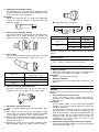
4. Extension bar: Code No. 873633
The extension bar is convenient for working in very
restricted spaces or when the socket provided cannot
reach the bolt to be tightened.
CAUTION
When the extension bar is used, the tightening
torque is reduced slightly compared with the
ordinary socket.
5. Universal joint:Code No. 992610
The universal joint is convenient for impacting nuts
when there is an angle between the socket and
wrench, or when working in a very narrow space.
6. Duct Socket
This is used for tightening bolts and nuts on flange
sections of air conditioners, type ducts, etc.
7. Corner attachment (Model EW-14R)
Use this attachment only when the machine is
applied to the nut or bolt at the right angle.
8. Bit adaptor: Code No. 991476
This is used for tightening small screws (M6 – M8).
NOTES
(1) This adaptor is set only on the anvil (drive angle)
of the main unit. The bit adapter cannot be attached
to the special accessory anvil (square drive).
(2) Before starting work with the adapter, tighten a few
screws with it to make sure it’s tightening with the
appropriate torque.
(3) Tightening speed will be greatly reduced when
driving wood, tapping or other similar screws.
Optional accessories are subject to change without
notice.
APPLICATION
䡬 Tightening and loosening of all types of bolts and
nuts, used for securing structural items.
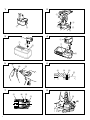
BATTERY REMOVAL/INSTALLATION
1. Battery removal
Hold the handle tightly and push the battery latch
to remove the battery (see Figs. 1 and 2).
CAUTION
Never short-circuit the battery.
2. Battery installation
Insert the battery while observing its polarities (see
Fig. 2).
CHARGING
〈UC12SD〉
Before using the impact wrench, charge the battery as
follows.
1. Insert the battery into the charger
Insert the battery firmly while observing its
direction, until it contacts the bottom of the charger
(See Fig. 3).
CAUTION
The UC12SD model is the exclusively designed
charger. This cannot charge batteries except the
specified batteries.
It is possible to insert the batteries other than the
specified into the charger and it may light up the
pilot lamps. However, you are requested to exercise
utmost caution not to charge batteries other than
specified ones because these can not only be
charged but also such actions can result in the
malfunction of chargers.
2. Connect the charger power cord to the receptacle
Connecting the power cord will turn on the charger
(the pilot lamp lights up).
Code No.
Hexagonal width
across flats (mm)
993658 12
992613 13
992615 14
䢇 Applicable plus driver bit
L 6.35
Bit No. L (mm) Code No.
No. 2
45 955229
70 955654
No. 3
45 955230
70 955655
Bit No.

8
CAUTION
If the pilot lamp does not light up, pull out the
power cord from the receptacle and check the battery
mounting condition.
About 1 hour is required to fully charge the battery
at a temperature of about 20°C. The pilot lamp goes
off to indicate that the batterry is fully charged.
The battery charging time becomes longer when a
temperature is low or the voltage of the power
source is too low.
When the pilot lamp does not go off even if more
than two hours have elapsed after starting of the
charging, stop the charging and contact your HITACHI
AUTHORIZED SERVICE CENTER.
CAUTION
If the battery is heated due to direct sunlight, etc.,
just after operation, the charger pilot lamp may not
light up. At that time, cool the battery first, then
start charging.
3. Disconnect the charger power cord from the receptacle
4. Hold the charger tight and pull out the battery
NOTE
After charging, pull out batteries from the charger
first, and then keep the batteries properly.
Regarding electric discharge in case of new batteries, etc.
As the internal chemical substance of new batteries
and batteries that have not been used for an
extended period is not activated, the electric
discharge might be low when using them the first
and second time. This is a temporary phenomenon,
and normal time required for recharging will be
restored by recharging the batteries 2 – 3 times.
How to make the batteries perform longer.
(1) Recharge the batteries before they become
completely exhausted.
When you feel that the power of the tool becomes
weaker, stop using the tool and recharge its battery.
If you continue to use the tool and exhaust the
electric current, the battery may be damaged and
its life will become shorter.
(2) Avoid recharging at high temperatures.
A rechargeable battery will be hot immediately after
use. If such a battery is recharged immediately after
use, its internal chemical substance will deteriorate,
and the battery life will be shortened. Leave the
battery and recharge it after it has cooled for a
while.
〈UC14YFA〉
Before using the impact wrench, charge the battery as
follows.
1. Connect the charger’s power cord to a receptacle
When the power cord is connected, the charger’s
pilot lamp will blink in red (At 1-second intervals).
2. Insert the battery into the charger
Insert the battery firmly, in the direction shown in
Fig. 4, until it contacts the bottom of the charger
compartment.
CAUTION
䡬 If the battery is inserted in the reverse direction,
not only recharging will become impossible, but it
may also cause the fuse to blow, or problems in
the charger such as deformed recharging terminal.
3. Charging
When inserting a battery in the charger, charging
will commence and the pilot lamp will light
continuously in red.
When the battery becomes fully recharged, the pilot
lamp will blink in red (At 1-second intervals.) (See
Table 3).
(1) Pilot lamp indication
The indications of the pilot lamp will be as shown
in Table 3, according to the condition of the charger
or the rechargeable battery.
Lights for 0.5 seconds. Does not light for
0.5 seconds. (off for 0.5 seconds)
Lights continuously
Lights for 0.5 seconds. Does not light for
0.5 seconds. (off for 0.5 seconds)
Lights for 0.1 seconds. Does not light for
0.1 seconds. (off for 0.1 seconds)
Lights continuously
Before
charging
While
charging
Charging
complete
Charging
impossible
Charging
impossible
Blinks
(RED)
Lights
(RED)
Blinks
(RED)
Flickers
(RED)
Lights
(GREEN)
Malfunction in the battery
or the charger.
The battery temperature
is high, making recharg-
ing impossible.
Table 3
Indications of the lamps

9
(2) Regarding the temperatures of the rechargeable
battery.
The temperatures for rechargeable batteries are as
shown in the table below, and batteries that have
become hot should be cooled for a while before
being recharged.
Table 4 Recharging ranges of batteries
(3) Regarding recharging time
Depending on the combination of the charger and
batteries, the charging time will become as shown
in Table 5.
Table 5 Charging time (At 20°C)
NOTE
The charging time may vary according to
temperature and power source voltage.
4. Disconnect the charger’s power cord from the
receptacle
5. Hold the charger firmly and pull out the battery
NOTE
After charging, pull out batteries from the charger
first, and then keep the batteries properly.
Regarding electric discharge in case of new batteries,
etc.
As the internal chemical substance of new batteries
and batteries that have not been used for an
extended period is not activated, the electric
discharge might be low when using them the first
and second time. This is a temporary phenomenon,
and normal time required for recharging will be
restored by recharging the batteries 2 – 3 times.
How to make the batteries perform longer.
(1) Recharge the batteries before they become
completely exhausted.
When you feel that the power of the tool becomes
weaker, stop using the tool and recharge its battery.
If you continue to use the tool and exhaust the
electric current, the battery may be damaged and
its life will become shorter.
(2) Avoid recharging at high temperatures.
A rechargeable battery will be hot immediately after
use. If such a battery is recharged immediately after
use, its internal chemical substance will deteriorate,
and the battery life will be shortened. Leave the
battery and recharge it after it has cooled for a while.
CAUTION
䡬 If the battery has been heated right after operation
(or due to sunlight, etc.), the charger’s pilot lamp
may not light in red. In such a case, first let the
battery cool, then start charging.
䡬 When the pilot lamp flikers in red quickly (at 0.2-
second intervals), check for and take out any foreign
objects in the charger’s battery installation hole. If
there are no foreign objects, it is probable that the
battery or charger is malfunctioning. Take it to your
Authorized Service Center.
䡬 Since the built-in micro computer takes about 3
seconds to confirm that the battery being charged
with UC14YFA is taken out, wait for a minimum of
3 seconds before reinserting it to continue charging.
If the battery is reinserted within 3 seconds, the
battery may not be properly charged.
PRIOR TO OPERATION
1. Preparing and checking the work environment
Make sure that the work site meets all the conditions
laid forth in the precautions.
2. Checking the battery
Make sure that the battery is installed firmly. If it
is at all loose it could come off and cause an accident.
3. Selecting the socket matched to the bolt
Be sure to use a socket which is matched to the
bolt to be tightened. Using an improper socket will
not only result in insufficient tightening but also in
damage to the socket or nut.
A worn or deformed hex. or square-holed socket
will not give an adequate tightness for fitting to the
nut or anvil, consequently resulting in loss of
tightening torque.
Pay attention to wear of socket hole, and replace
before further wear has developed.
Finally, install the socket prescribed in Item 4. The
section on “Optional Accessories” details the
relationship between bolt sizes and sockets. Sockets
are named according to the dihedral width of the
hexagonal hole.
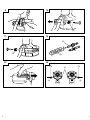
4. Installing a socket
Select the socket to be used.
䢇 Pin, O-ring type (Fig. 5 and 6)
(1) Align the hole in the socket with the hole in the
anvil and insert the anvil into the socket.
(2) Insert the pin into the socket.
(3) Attach the ring to the groove on the socket.
䢇 Plunger type (Fig. 7)
Align the plunger located in the square part of the
anvil with the hole in the hex. socket. Then push
the plunger, and mount the hex. socket on the anvil.
Check that the plunger is fully engaged in the hole.
When removing the socket, reverse the sequence.
HOW TO USE
CAUTION
䡬 When using the hook, pay sufficient attention so
that the main equipment does not fall. If the tool
falls, there is a risk of accident.
䡬 Do not attach the tip tool except phillips bit to the
tool main unit when carrying the tool main unit with
the hook suspended from a waist belt.
Injury may result if you carry the equipment
suspended from the waist belt with sharp tipped
components such as drill bit attached.
Temperatures at
Rechargeable batteries which the battery
can be recharged
EB1220BL –5°C – 60°C
EB1226HL 0°C – 45°C
Charger
UC14YFA
Battery
EB1220BL Approx. 50 min.
EB1226HL Approx. 60 min.

10
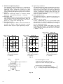
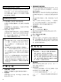
1. Using the hook
The hook can be installed on the right or left side
and the angle can be adjusted in 5 steps between
0° and 80°.
(1) Operating the hook
(a) Pull out the hook toward you in the direction
of arrow (A) and turn in the direction of arrow
(B) (Fig. 8).
(b) The angle can be adjusted in 5 steps (0°, 20°,
40°, 60°, 80°).
Adjust the angle of the hook to the desired
position for use.
(2) Switching the hook position
CAUTION
Incomplete installation of the hook may result in
bodily injury when used.
(a) Securely hold the main unit and remove the
screw using a slotted head screwdriver or a coin
(Fig. 9).
(b) Remove the hook and spring (Fig. 10).
(c) Install the hook and spring on the other side and
securely fasten with screw (Fig. 11).
NOTE
Pay attention to the spring orientation. Install the
spring with larger diameter away from you (Fig. 11).
(3) Using the bit holder
䡬 Installing the bit
Slide the bit from the side in the direction of
Fig. 12, and then insert firmly until the groove
on the bit locks in the protruded section of the
hook.
䡬 Removing the bit
Securely hold the main unit and pull out the bit
by holding the tip with your thumb (Fig. 13).
CAUTION
䡬 The socket may come loose from the hook and
cause bodily injury when reversing the direction of
the bit as shown in Fig. 12 or when using the
wrench with the bit stored incomplete.
䡬 Only Hitachi OPTIONAL ACCESSORIES plus driver
bits (Bit No. 2; Code No. 992671, Bit No. 3; Code
No. 992672) may be used. Do not use other bits
since they may come loose.
2. Check the rotational direction
The socket rotates clockwise (viewed from the rear
side) by pushing the R-side of the push button.
The L-side of the push button is pushed to turn the
bit counterclockwise (See Fig. 14) (The
L
and
R
marks are provided on the body.).
CAUTION
The push button can not be switched while the
impact wrench is turning. To switch the push button,
stop the impact wrench, then set the push button.
3. Switch operation
䡬 When the trigger switch is depressed, the tool rotates.
When the trigger is released, the tool stops.
䡬 The rotational speed can be controlled by varying
the amount that the trigger switch is pulled. Speed
is low when the trigger switch is pulled slightly and
increases as the trigger switch is pulled more.
4. Tightening and loosening bolts
A hex socket matching the bolt or nut must first
be selected. Then mount the socket on the anvil,
and grip the nut to be tightened with the hex socket.
Holding the wrench in line with the bolt, press the
power switch to impact the nut for several seconds.
If the nut is only loosely fitted to the bolt, the bolt
may turn wit the nut, therefore mistaking proper
tightening. In this case, stop impact on the nut and
hold the bolt head with a wrench before restarting
impact, or manually tighten the bolt and nut to
prevent them slipping.
5. Number of bolt tightened possible
Please refer to the table below for the number of
bolt tightened possible with one charge.
For WR12DAF (EB1214L)
These values may vary slightly, according to
surrounding temperature and battery characteristics.
NOTE
The use of the battery EB1226HL in a cold condition
(below 0 degree Centigrade) can sometimes result
in the weakened tightening torque and reduced
amount of work. This, however, is a temporary
phenomenon, and returns to normal when the
battery warms up.
OPERATIONAL CAUTIONS
1. Resting the unit after continuous work
After use for continuous bolt-tightening work, rest
the unit for 15 minutes or so when replacing the
battery. The temperature of the motor, switch, etc.,
will rise if the work is started again immediately after
battery replacement, eventually resulting in burnout.
NOTE
Do not touch the hammer case, as it gets very hot
during continuous work.
2. Cautions on use of the speed control switch
This switch has a built-in, electronic circuit which
steplessly varies the rotation speed. Consequently, when
the switch trigger is pulled only slightly (low speed
rotation) and the motor is stopped while continuously
tightening in bolts, the components of the electronic
circuit parts may overheat and be damaged.
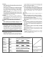
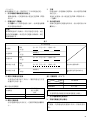
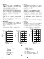
3. Tightening torque
Refer to Fig. 15 for the tightening torque of bolts
(according to size), under the conditions shown in
Fig. 16. Please use this example as a general
reference, as tightening torque will vary according
to tightening conditions.
4. Work at a tightening torque suitable for the bolt
under impact
The optimum tightening torque for nuts or bolts
differs with material and size of the nuts or bolts.
An excessively large tightening torque for a small
bolt may stretch or break the bolt. The tightening
torque increases in proportionate to the operaton
time. Use the correct operating time for the bolt.
5. Holding the tool
Hold the impact wrench firmly with both hands. In
this case hold the wrench in line with the bolt.
It is not necessary to push the wrench very hard.
Hold the wrench with a force just sufficient to
counteract the impact force.
Bolt used No. of tightenings
High tension bolt
Approx. 120
M12 × 45

11
100
80
60
40
20
0
0123
1000
800
600
400
200
0
1201200
kgf
•
cm
N
•
m
M12 × 45
100
80
60
40
20
0
0123
1000
800
600
400
200
0
kgf
•
cm
N
•
m
M10 × 30
Tightening torque
6. Confirm the tightening torque
The following factors contribute to a reduction of
the tightening torque. So confirm the actual
tightening torque needed by screwing up some
bolts before the job with a hand torque wrench.
Factors affecting the tightening torque are as follows.
(1) Voltage
When the discharge margin is reached, voltage
decreases and tightening torque is lowered.
(2) Operating time
The tightening torque increases when the operating
time increases. But the tightening torque does not
increase above a certain value even if the tool is
driven for a long time (See Fig. 15).
(3) Diameter of bolt
The tightening torque differs with the diameter of
the bolt as shown in Fig. 15. Generally a larger
diameter bolt requires larger tightening torque.
(4) Tightening conditions
The tightening torque differs according to the torque
ratio; class, and length of bolts even when bolts
with the same size threads are used. The tightening
torque also differs according to the condition of the
surface of workpiece through which the bolts are
to be tightened. When the bolt and nut turn together,
torque is greatly reduced.
(5) Using optional parts
The tightening torque is reduced a little when an
extension bar, universal joint or a long socket is
used.
(6) Clearance of the socket
A worn or deformed hex or a square-holed socket
will not give an adequate tightness to the fitting
between the nut or anvil, consequently resulting in
loss of tightening torque.
Using an improper socket which does not match
to the bolt will result in an insufficient tightening
torque. Matching socket and bolt sizes are shown
in Table 1 and 2.
Nut
Bolt
Steel plate thickness t
Washer
Washer
Fig. 16
Tightening torque
Tightening torque
Tightening time: sec
(Steel plate thickness
t = 10 mm)
Tightening time: sec
(Steel plate thickness
t = 10 mm)
Tightening time: sec
(Steel plate thickness
t = 10 mm)
Fig. 15
100
80
60
40
20
0
0123
1000
800
600
400
200
0
kgf
•
cm
N
•
m
M8 × 30
Explanation of strength grade:
4 — Yield point of bolt: 32 kgf/mm
2
8 — Pulling strength of bolt: 40 kgf/mm
2
*The following bolt is used.
Ordinary bolt: Strength grade 4.8
High tensile bolt: Strength grade 12.9
)(
High tension bolt
Ordinary bolt
High tension bolt
Ordinary bolt
Ordinary bolt
High tension
bolt

12
MAINTENANCE AND INSPECTION
1. Inspecting the socket
A worn or deformed hex or a square-holed socket
will not give an adequate tightness to the fitting
between the nut or anvil, consequently resulting in
loss of tightening torque. Pay attention to wear of
a socket holes periodically, and replace with a new
one if needed.
2. Inspecting the mounting screws
Regularly inspect all mounting screws and ensure
that they are properly tightened. Should any of the
screws be loose, retighten them immediately. Failure
to do so could result in serious hazard.
3. Cleaning on the outside
When the impact drill is stained, wipe with a soft
dry cloth or a cloth moistened with soapy water.
Do not use chloric solvents, gasoline or paint thinner,
for they melt plastics.
4. Storage
Store the impact drill in a place in which the
temperature is less than 40°C and out of reach of
children.
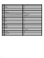
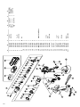
5. Service parts list
A: Item No.
B: Code No.
C: No. Used
D: Remarks
CAUTION
Repair, modification and inspection of Hitachi Power
Tools must be carried out by a Hitachi Authorized
Service Center.
This Parts List will be helpful if presented with the
tool to the Hitachi Authorized Service Center when
requesting repair or other maintenance.
In the operation and maintenance of power tools,
the safety regulations and standards prescribed in
each country must be observed.
Modification
Hitachi Power Tools are constantly being improved
and modified to incorporate the latest technological
advancements.
Accordingly, some parts (i.e. code numbers and/or
design) may be changed without prior notice.
NOTE
Due to HITACHI’s continuing program of reserch and
development, the specifications herein are subject to
change without prior notice.

13
°

14
° °
°
°

15
ISO ISO
LL1øF
10 mm 944291 M6 10 B 40 8 18
12 mm 873632 M8 W5/16" 12 B 40 8 20
13 mm 873539 M8 13 B 40 9 25
12.7
14 mm 873540 M10 14 B 40 9 25
17 mm 873536 M10 M12 W3/8" 17 C 32 8 28
19 mm 873624 M12 M14 W7/16" 19 C 34 9 28
21 mm 873626 W1/2" 21 D 36 10 32
22 mm 873627 M12 M14 M16 22 D 40 14 35
H S
L
L1
ØF
H S
L
L1
ØF
H S
L
L1
ØF
H
S
L1
L2
L
ØF
H S
L1
L2
L
ØF
H
S
L1
L2
L
ØF

16
ISO ISO
LL1L2øF
12 mm 955138 M8 W5/16" 12 B 52 20 34 20
13 mm 955139 M8 13 B 52 20 34 21.5
14 mm 955140 M10 14 B 52 20 34 22
17 mm 955141 M10 M12 W3/8" 17 B 52 24 34 25
17 mm 955149 M10 M12 W3/8" 17 B 75 24 57 25
12.7 19 mm 955142 M12 M14 W7/16" 19 B 52 24 34 28
19 mm 955150 M12 M14 W7/16" 19 B 75 24 57 28
21 mm 955143 W1/2" 21 D 52 24 34 31
21 mm 955151 W1/2" 21 D 75 24 57 31
21 mm 991480 W1/2" 21 D 125 24 107 31
22 mm 955144 M12 M14 M16 22 D 52 24 34 32.5
993658 12
992613 13
992615 14

17
●
6.35
(mm)
No. 2
45 955229
70 955654
No. 3
45 955230
70 955655
䡬
°

18
EB1220BL –5°C – 60°C
EB1226HL 0°C – 45°C
UC14YFA
EB1220BL
EB1226HL

19
䡬
䡬
䡬
●
●
䡬
䡬
ページが読み込まれています...
ページが読み込まれています...
ページが読み込まれています...
ページが読み込まれています...
ページが読み込まれています...
ページが読み込まれています...
-
 1
1
-
 2
2
-
 3
3
-
 4
4
-
 5
5
-
 6
6
-
 7
7
-
 8
8
-
 9
9
-
 10
10
-
 11
11
-
 12
12
-
 13
13
-
 14
14
-
 15
15
-
 16
16
-
 17
17
-
 18
18
-
 19
19
-
 20
20
-
 21
21
-
 22
22
-
 23
23
-
 24
24
-
 25
25
-
 26
26


他の言語で
- English: Hikoki WR 12DAF User manual
関連論文
その他のドキュメント
-
Hitachi UC 7SL Handling Instructions Manual
-
-
Hitachi WH 18DBEL Handing Instructions
-
REXON IW140R 取扱説明書
-
-
-
-
-
-
Makita TW202D Cordless Impact Wrench ユーザーマニュアル