
TLK03001G
TLK02001G TLK02002G
TLK01101* TLK01102*
TLK01103* TLK01104*
安装说明书
Installation Manual
Warranty Registration and Inquiry
For product warranty registration, TOTO U.S.A. Inc. recommends online warranty registration. Please visit
our web site http://www.totousa.com. If you have questions regarding warranty policy or coverage, please
contact TOTO U.S.A. Inc., Customer Service Department, 1155 Southern Road, Morrow, GA 30260
(888) 295-8134 or (678) 466-1300 when calling from outside of U.S.A.
首先对您能选购本公司产品表示我们最真挚的谢意。
请仔细阅读本说明书后正确使用。
本说明书内附有保证书,请妥善保管,并在必要时取出阅读。
自动感应皂液器
Automatic Soap Dispenser

2
部品名称
INCLUDED PARTS........................................................................................................ 3
安装步骤 INSTALLATION PROCEDURE ..................................................................................... 5
试运行 TESTING .........................................................................................................................13
TOTO致力于为世界提供更健康、卫生和舒适的生活方式。对于每一件产品,我们均以形式和功
能的平衡统一作为指导原则来设计。祝贺您作出了正确的选择。
The mission of TOTO is to provide the world with healthy, hygienic and more comfortable lifestyles.
We design every product with the balance of form and function as a guiding principle.
Congratulations on your choice.
目录 TABLE OF CONTENTS
感谢您选购TOTO! THANK YOU FOR CHOOSING TOTO!
请阅读并遵守以下注意事项。否则可能导致人员伤亡或财产损失。
警告 WARNINGS
安装前 BEFORE INSTALLATION
除非本手册中特别说明,除售后服务工程师以外的人员不得拆卸、修理或改造本皂液器。
否则可能会导致触电或产品故障。
请勿在表面可能积聚冷凝水的潮湿环境(特别是桑拿房或蒸汽室)使用本皂液器。
请勿敲击或踢打吐皂口本体或机能部,否则可能会导致产品损坏或引起泄漏。
请勿在室温低于冰点的房间使用本皂液器。
请确保电源线不与热水供水管接触。
请避免在红外感应器检测范围内放置任何物品。
仅可使用TOTO指定的皂液才能避免保修失效。
请确保电源插座位于使用期间不会受潮的位置。
Please read and adhere to the following notes. Failure to do so could result in personal injury
and/or property damage.
No person other than a service engineer should disassemble, repair or modify this
dispenser, unless it is specifically described in this manual. Failure to do so may result in
electric shock or product malfunction.
Do not use this dispenser in a humid location where condensation may collect on the
surface, especially in a sauna or steam room.
Do not strike or kick the dispenser or controller box, as this may damage the unit or cause a leak.
Do not use this dispenser if the room temperature drops below freezing.
Make sure the power cord does not come in contact with the hot water supply line.
Avoid placing any objects within the detection range of the infrared sensor.
Use only TOTO approved liquid soap to avoid invalidation of warranty.
Make sure the electrical outlet is in a position where it will not get wet during use.
为确保正确进行安装,请仔细阅读这些说明。
TOTO保留更新产品设计的权利,恕不另行通知。
请进行检查,确认您的产品中包含以下页面中显示的部件。
Read these instructions carefully to ensure proper installation.
TOTO reserves the right to update product design without notice.
Check to make sure you have the parts indicated on the following page.
3
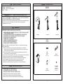
部品名称 INCLUDED PARTS
吐皂口本体
Controller
机能部
Spout parts
安装支架
Mounting bracket
沉头自攻螺丝
(Φ4x10)
Countersunk
tapping screw
(Φ 4 x 10)
螺丝
(Φ5 .1x 32)
Screw
(Φ 5.1 x 32)
固定板
Anchoring plate
(TLK03001G) (TLK02001G) (TLK02002G)

4
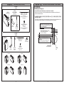
部品名称(续) INCLUDED PARTS
(Continued)
TLK01104*
TLK01101*
3L tank
3L皂液箱
支架组
(仅用于3L皂液箱)
Bracket set
(for 3L tank only)
Supply port cap
注液口盖
1L tank
1L皂液箱
Supply port cap
注液口盖
支架 绑扎带
Bracket Bundling
band
皂液软管 180mm
圆头螺丝
(Φ5 .1x 3 2)
Round-head screw
(Φ 5.1 x 32)
Hose 180 mm
软管夹:2个
Hose clamp: 2
支架
Bracket
螺丝
Screw
装饰螺丝
Decorative
screw
皂液软管 2m(单一型:1根,
双联型:2根,三联型:3根)
Hose 2 m
(Single type: 1, Double type: 2,
Triple type: 3)
软管夹
(单一型:2个,双联型:4个,
三联型:6个)
Hose clamp
(Single type: 2, Double type: 4,
Triple type: 6)
TLK01102*
TLK01103*
5
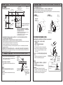
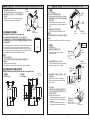
安装步骤-定位 INSTALLATION PROCEDURE - POSITIONING
1.为防止意外触发,吐皂口本体和水龙头之间至少留出120mm的空间。
Make sure to leave at least 120 mm of space between the soap dispenser and the faucet to
prevent accidental activation.
2.从洗面器的内边缘到吐皂口本体安装孔最大需留出80mm的空间,以确保皂液器吐皂口的残留
皂液可滴入洗面器中。
Leave 80 mm of space maximum from the inside edge of the sink to the spout installation hole to
ensure that any residual soap drips from the dispenser spout into the sink bowl.
定位吐皂口本体
Positioning the Dispenser
(1)
给皂口本体与水龙头之间的空间最小为120mm
Space between the dispenser and the faucet
to be 120mm minimum
(2)从给皂口本体到洗面器边缘的距离
最长是80mm
The distance from the soap dispenser to the
edge of the sink to be 80 mm maximum
自动感应皂液器
Auto soap dispenser
洗面器
Sink
水龙头
Faucet
给皂口本体安装孔[直径25~28mm]
Hole for installing the dispenser
[25~28 mm in diameter]

6
安装步骤-定位
(续)
INSTALLATION PROCEDURE - POSITIONING
(Continued)
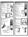
定位皂液箱
Positioning the Tank
*图中的尺寸仅限于将箱体安装在左侧的情况。
如果实际尺寸超过图中的尺寸,感应器连接线
和皂液软管的长度可能不足。
* The dimensions in the figure are limited to when
the tank is installed on the left end.
If actual dimensions exceed those in the figure,
cords and hoses may not reach.
Install the liquid soap water tank within 800 mm from the upper face of the counter. It also should
not exceed the height of the upper end of the controller.
It cannot be installed on the counter or on the lower level.
If it is installed beyond this range, the following troubles may occur. Less water spouts and the
soap does not foam.
The length of the hose connected to the spout is 1.8 m. Install the controller so that the hose can
be connected to the controller.
将皂液箱安装在距离台面上表面800mm的范围之内。它也不应该超过机能部上端的高度。
它不能安装在台面上或更低平面上。
如果超出此范围安装,可能会出现以下故障。喷皂液少和皂液不起泡。
连接到吐皂口本体的皂液软管的长度是1.8m。安装机能部时应使皂液软管可以连接到机能部。
单位: mm
Unit : mm
安装步骤-吐皂口本体 INSTALLATION PROCEDURE - Spout
Dispenser
吐皂口本体
Sensor cord
1.
将吐皂口本体插入台面(或洗面器)的安装孔中。
Insert the dispenser into the installation holes
in the counter (or the sink).
Caution
Make sure that the cords and tubes do not get
crimped.
注意
确保感应器连接线和管路没有发生扭曲。
2.依次安装垫片和六角螺母。
Disassemble screw and washer with the hex
nuts.
Washer
垫片
Hex nut
六角螺母
感应器连接线
Air hose (blue)
空气软管(蓝色)
Liquid soap hose
(clear)
皂液软管(透明)
Packing
密封圈
* For a spout-to-spout distance
of 650 mm
*
吐皂口本体到吐皂口本体距离为650mm
Less than 1400
(Height of functional unit:350)
小于1400
(机能部的高度:350)
Less than 1500
小于1500
Tank
皂液箱
Controller
机能部
Controller installable range
(*1500)
机能部可安装范围
(*1500)
Spouts
吐皂口本体
Less than 800
小于800
7
Marking of the positions of the screw holes for the anchoring plate
Decide the anchoring position of the controller and mark the positions of screw holes on the wall by
referring to the dimensional drawing.
标记固定板螺丝孔的位置
根据尺寸图确定机能部的固定位置,并在墙壁上标记螺丝孔位置。
Reference
anchoring screw
Reference
anchoring screw
Controller (Back side)
Anchoring plate
Countersunk
tapping screw
(Φ 4 x 10)
沉头自攻螺丝
(Φ4 x 10)
固定板
固定板
沉头自攻螺丝(Φ4 x 10)
机能部(背面)
Anchoring plate
Countersunk tapping screw
(Φ 4 x 10)
正面 反面
Top side Bottom side
安装步骤-机能部 INSTALLATION PROCEDURE - Functional Unit
[3L箱型]
[ 3L Tank Type ]
[1L箱型]
[ 1L Tank Type ]
单位: mm
Unit : mm
基准固定螺丝
基准固定螺丝
膨胀管
Installing the controller on a tiled or concrete wall
将机能部安装在瓷砖或混凝土墙体上
* Procure a curl plug that matches the screw
(Φ 5.1 x 32).
*请购买与螺丝相匹配的膨胀管
(Φ5.1 x 32)。
1.在螺丝孔位置钻孔,然后插入膨胀管
(现场购买)。
Drill a rough hole at the screw hole position
and drive in the curl plug (procure in the field).
2.使用一个沉头自攻螺丝将固定板固定到机能
部上。
Anchor the anchoring plate to the controller
with one countersunk tapping screw.
注意
请勿用电动螺丝刀拧紧螺丝。这些螺丝仅可
手动拧紧。
注意请勿装反固定板的正面和反面。
Caution
Do not tighten the screws with an electric
screwdriver. These should be tightened manually.
Pay attention not to confuse the top side and
the bottom side of the anchoring plate.
Anchor
94
149
47
70
149
20
47
137
94

8
3.用两颗螺丝定位并固定支架。
4.
将机能部挂在安装支架上,并用一颗螺丝固定其
固定板。
Position and anchor the bracket with two screws.
Confirm that the wooden wall has a structure that can sustain the weight (2 kg)
of the controller (Triple type). (In the case of dry wall, in order to hold the
controller, make sure the plywood base is more than 0.5 inch thick.) Anchor
the mounting bracket with two screws and anchor the anchoring plate with one
screw. Reinforce the wall structure sufficiently as needed.
确认木质墙体的结构能够承受机能部(三联型)的重量(2kg)。
(如果墙体干燥,为了支 撑 机能部,请确保胶合板基层厚度大于12mm。)
用两颗螺丝固定安装支架,然后用一颗螺丝固定其固定板。根据需要充
分加固墙体结构。
Hang the controller on the mounting bracket and
anchor the anchoring plate with one screw.
安装步骤-机能部
(续)
INSTALLATION PROCEDURE - Functional Unit
(Continued)
Relation between the screw positions and the side and lower face
[3L箱型]
[ 3L Tank Type ]
单位: mm
机能部
螺丝
安装支架
固定板
螺丝
Unit : mm
[1L箱型]
[ 1L Tank Type ]
螺丝位置与侧面和下表面之间的关系
将机能部安装在木质墙体上
Controller
Mounting bracket
Screws
Screw
Installing the controller on a wooden wall
Anchoring plate
25 2594
149
11
47
72
72
13733
117
149
47
43 72
22
113 94 25
138
11
138
Caution
Install the unit body horizontally.
Pay attention not to pinch of the electric cord or contact it with edges.
注意
请水平安装机能部。
注意请勿夹住感应器连接线或使感应器连接线碰触到边缘。
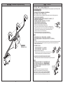
9
Anchor the tank and the brackets with the
decorative screws that should be tightened by
hand.
Using the bracket to anchor the tank on the floor.
使用支架将皂液箱固定在地板上。
Install the tank on the floor with the screw.
2.将皂液箱收缩部分完全卡入支架。
Pass the constricted part of the tank between
the bracket and insert it the full depth.
Insert the tank in the slit on the bottom
surface of the bracket and pass it through
the two holes.
安装步骤-皂液箱
INSTALLATION PROCEDURE - Tank
1.用随附的圆头螺丝固定支架。
2.用螺丝将皂液箱安装在地板上。
1.使用装饰螺丝(应该用手拧紧)将皂液箱和支
架进行固定。
Anchor the bracket with the attached
round-head screw.
[1L箱型]
[ 1L Tank Type ]
[3L箱型]
[ 3L Tank Type ]
Note
If the floor is made of concrete, embed the curl plugs first.
Bracket
Decorative screw
1.装饰螺丝
Tank
Screw
2.螺丝
Two round-head
screws
(Φ 5.1 x 32)
Bracket
Wall surface
墙面
Insert it the full
depth.
Constricted part
Hole
Slit on the bottom of
the tank anchoring plate
Bundling band
3.
4.系上绑扎带。
3.将皂液箱插入支架底面上的狭缝中,并使
其穿过两个孔。
Attaching the bundling band.
*
绑扎带用于防止皂液箱与物体碰撞时掉落。
如果皂液箱安装在墙体等的后面,则不
需要系上绑扎带。
* The bundling band serves to prevent the
tank from falling off if the tank collides with
something.
If the tank is installed behind a wall, etc., it is
not necessary to attach the bundling band.
皂液箱固定板
底面上的狭缝
4.绑扎带
2.将其完全卡入。
孔
支架
收缩部分
两颗圆头螺丝
(Φ5.1 x 32)
Bracket
支架
皂液箱
支架
提示
如果地板是混凝土材质,则需首先插入膨胀管。

10
2. 将皂液
软管完全插入机能部,然
后将软管夹放在接头的凸出部
分上来牢固地固定皂液软管。
安装步骤-连接皂液软管和感应器连接线
INSTALLATION PROCEDURE - Connecting Hoses and Cords
[皂液箱侧]
[控制器侧]
3L皂液箱
1L皂液箱
*将单一型仅连接到 。(在其他位置感应器不响应。)
*将双联型连接到 和 。( 不工作。)
* Connect the single type to only. (The sensor does not work in any other position.)
* Connect the double type to and . ( does not work.)
皂液软管(透明)
连接到皂液箱。
皂液软管(透明)
连接到吐皂口本体。
空气管(蓝色)
连接到吐皂口本体。
Insert the hose fully into the
controller and put the hose clamp
on the projection of the joint to
anchor the hose securely.
[ Tank side ]
[ Controller side ]
3L TANK
1L TANK
皂液软管
软管夹
接头的凸出部分
Hose
Hose clamp
Projection of joint
Liquid soap hose (clear)
Connect it to the tank.
Liquid soap hose (clear)
Connect it to the spout.
Air hose (blue)
Connect it to the spout.
注意
使用剪刀等剪断皂液软管,使剪切表面垂直。
1. 将皂液软管剪切至适当的长度,以达到所
连接的部分。
(在吐皂口本体和机能部之间)
(在机能部和皂液箱之间)
注意
按预定的配对连接皂液软管和感应器。
插入皂液软管时,注意请勿对皂液箱的接头施加强力。
注意请勿弯折皂液软管。
皂液软管连接
Caution
Using a cutter, etc., cut the hoses so that the
cut surface becomes vertical.
Cut the hoses to an appropriate length that
reaches to the connected part.
(Between the spouts and the controller)
(Between the controller and the tank)
Caution
Connect the hoses and sensors in the predetermined pairs.
When inserting the hoses, pay attention not to apply strong
force to the joint of the tank.
Pay attention not to bend the hoses.
Hose Connections
按预定的配对连接
皂液软管和感应器。
Connect the hoses
and sensors in the
predetermined pairs.
11
感应器仅用接插件 (白色)
感
应器用接插件 (白色)和 (黄色)
感应器用接插件 (白色)、 黄色和 (蓝色)
安装步骤-连接皂液软管和感应器连接线
(续)
INSTALLATION PROCEDURE - Connecting Hoses and Cords
(Continued)
[
感应器连接线
] [浮子开关连接线]
绑扎夹
机能部
皂液箱
绑扎夹
Connector (white) for sensor only
Connectors (white) and (yellow) for sensor
Connectors (white), (yellow) and (blue) for sensor
[ Sensor cord ] [ Float switch cord ]
Bundling
clamp
Controller
Tank
Bundling clamp
在一个地方连接。
在两个地方连接。
在三个地方连接。
注意
连接到吐皂口本体的感应器的所有接插
件均是白色。
设置在机能部中的接插件的颜色是白色、
黄色和蓝色。可能会发生连接了与此不同
的颜色。
拆下机能部的罩盖,然后将感应器接插件连接到浮子开关接插件。
将感应器接插件和皂液软管连接在规定的位置。
连接头连接
使用绑扎夹,整理和绑扎连接线。
连接线的绑扎
侧面(布线视图)
单一安装
双联安装
三联安装
按预定的配对连接
皂液软管和感应器。
白色 黄色 蓝色
插口(感应器)
浮子开关
接插件(感应器,白色)
布线图
Connect in one place.
Connect in two places.
Connect in three places.
Caution
All connectors of the sensors connected to
the spout are white.
The colors of the connectors arranged in the
controller are white, yellow and blue.
Different colors may be connected.
Remove the cover of the controller and connect the sensor connector to
the float switch connector.
Connect the sensor connector and the hose in the prescribed positions.
Connector Connections
Using bundling clamps, stow and bundle the cords.
Bundling of Cords
Side face (View of wiring)
For single installation
For double installation
For triple installation
Connect the hoses
and the sensors in
predetermined pairs.
White Yellow Blue
Socket (Sensors)
Float switch
Connector (Sensors, white)
Wiring Image

12
安装完成图
Installation Completion Drawing
连接线的绑扎
Bundling of cords
13
Shift the mode to the installation checking mode.
When your hand is held under the sensor for about 8 sec. during the first 10
minutes after the power is turned on, the mode shifts to the “Installation Mode”.
During sensing, the liquid soap pump is driven and the liquid soap
continues to come out. (30 sec at maximum)
The liquid soap stops when your hand leaves the sensor.
Use this function for filling an empty flow path with liquid soap.
试运行
TESTING
Checking after the completion of installation.
安装完成后进行检查。
安装完成后,使用以下方法确认皂液器是否正常工作。
安装工作完成后,使用以下步骤进行试运行。
After installation is complete, confirm that the dispenser is working properly using the following method.
After the installation has been compleated, test the product using the following procedure.
Caution
If more than 10 minutes pass since the power was turned on, pull out the power plug and insert it again.
When disconnecting and reconnecting the power plug, pull out the power plug and leave it
unplug for longer than 10 sec.
Caution
If the product is not used for a long period of time after
installation, liquid soap remaining in the hose dries and
dispenses poorly. Therefore, conduct the trial run with water.
After the trial run, leave water accumulated in the tank as is
and replace it with liquid soap at the beginning of actual use.
Sensor
Checking
for leaks
检查泄漏
注意
如果安装后长时间不使用本产品,则皂液软管中剩余的皂
液会干燥并导致出皂液不畅。因此,请用水进行试运行。
试运行结束后,请将皂液箱中的积水保持原样,并在实际
使用开始时更换为皂液。
Check the tank and the connection of the liquid soap hose for any liquid soap leaks.
3.检查皂液箱以及检查皂液软管的连接处是否有皂液泄漏。
Dispense and stop the liquid soap.
2.出皂液和停止出皂液。
1.将工作模式切换到安装检查模式。
在电源开启后的10分钟内,当您的手放在传感器下方约8秒钟时,工作
模式会切换到“安装检查模式”。
感应期间,会驱动皂液泵,皂液持续流出。(最长30秒钟)
当您的手离开感应器时,皂液会停止流出。
使用此功能会将空的皂液流动路径充满皂液。
注意
如果电源开启超过10分钟,需拔出电源插头,然后重新插入。
当断开并重新连接电源插头时,需拔出电源插头并保持拔下状态10秒钟以上。
感应器
The liquid soap comes out when you bring your hand under the sensor.
The liquid soap stops when your hand leaves the sensor.
当您将手放在感应器下方时,皂液会流出。
当您的手离开感应器时,皂液会停止流出。

14
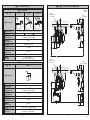
规格 SPECIFICATIONS
<标配> <Standard>
配置 Configuration
皂液吐出量 Soap volume
额定功率 Wattage
电源 Power supply
AC 100~240V 输出:12V DC AC 100240 V Output : 12 V DC
6.5 W
4 W
4 W 9 W
1~40°C
使用环境湿度 Humidity
最大90%RH Max.90% RH
550 mm
1.2g(出厂设置) 1.2 g (at factory setting)
型号 Type
TLK01101* TLK01102* TLK01103*
<标配> <Standard>
型号 Type
TLK01104*
规格 Specifications
配置 Configuration
皂液吐出量 Soap volume
额定功率 Wattage
电源 Power supply
AC 100~240V 输出:12V DC AC 100240 V Output : 12 V DC
1~40°C
使用环境湿度 Humidity
130~200mm 感应器自调节
最大90%RH
Max.90% RH
550 mm
1.2g(出厂设置) 1.2 g (at factory setting)
规格 Specifications
130200 mm sensor is self-adjusting
130~200mm 感应器自调节
130200 mm sensor is self-adjusting
皂液箱容量
Tank Capacity
皂液箱容量
Tank Capacity
Power Cord Length
电源线长度
1~17 mPa s
Suitable for soap viscosity
适用皂液粘度
Power Cord Length
1
~17 mPa s
Suitable for soap viscosity
电源线长度
适用皂液粘度
Ambient Temperature
使用环境温度
Ambient Temperature
使用环境温度
Sensor detection range
感应器检测范围
Sensor detection range
感应器检测范围
约3L(可
用容量)
Approximately 3 L (Usable Capacity)
约1L(可用容量)
Approximately 1 L (Usable Capacity)
15
安装尺寸图
INSTALLATION DIMENSIONS
单位:mm
Unit: mm
350
159
87
144
Mounting hole
Φ 25 ~ Φ 28
安装孔
Wall surface
墙面
Wall surface
墙面
130
108
28
302
Mounting hole
Φ 25 ~ Φ 28
安装孔
350
159
144
120
195
108
28
130
-
 1
1
-
 2
2
-
 3
3
-
 4
4
-
 5
5
-
 6
6
-
 7
7
-
 8
8


