


1

2

3

D28710
Voltage V 220-240
Frequency Hz 50/60
Power input W 2200
No-load speed min
-1
3800
Min. peripheral speed
cutting disc m/s 80
Disc diameter mm 355
Disc bore mm 25.4
Disc body thickness mm 3.1
Type of cutting disc straight, non-recessed
Cross-cutting capacity at 90°
circular mm 130
square mm 120 x 120
rectangular mm 115 x 130
angular mm 137 x 137
Cross-cutting capacity at 45°
circular mm 115
square mm 107 x 107
rectangular mm 115 x 107
angular mm 115 x 115
Weight kg 16.6
ENGLISH
chopsaw
D28710
Congratulations!
You have chosen a DeWALT tool. Years of
experience, thorough product development and
innovation make DeWALT one of the most reliable
partners for professional power tool users.
Technical Data
avoided, may result in minor or
moderate injury.
NOTICE: Indicates a practice not
related to personal injury which, if
not avoided, may result in property
damage.
Denotes risk of electric shock.
Denotes risk of fire.
WARNING: To reduce the risk of
injury, read the instruction manual.
General Power Tool Safety Warnings
WARNING! Read all safety warnings
and all instructions. Failure to follow
the warnings and instructions may result
in electric shock, fire and/or serious injury.
SAVE ALL WARNINGS AND INSTRUCTIONS
FOR FUTURE REFERENCE
The term “power tool” in the warnings refers
to your mains-operated (corded) power tool or
battery-operated (cordless) power tool.
1) WORK AREA SAFETY
a) Keep work area clean and well lit.
Cluttered or dark areas invite accidents.
b) Do not operate power tools in explosive
atmospheres, such as in the presence of
flammable liquids, gases or dust. Power tools
create sparks which may ignite the dust or
fumes.
c) Keep children and bystanders away
while operating a power tool. Distractions
can cause you to lose control.
2) ELECTRICAL SAFETY
a) Power tool plugs must match the outlet.
Never modify the plug in any way. Do
not use any adapter plugs with earthed
(grounded) power tools. Unmodified plugs
and matching outlets will reduce risk of
electric shock.
b) Avoid body contact with earthed or
grounded surfaces such as pipes,
radiators, ranges and refrigerators. There
is an increased risk of electric shock if your
body is earthed or grounded.
Definitions: Safety Guidelines
The definitions below describe the level of severity
for each signal word. Please read the manual and
pay attention to these symbols.
DANGER: Indicates an imminently
hazardous situation which, if not
avoided, will result in death or
serious injury.
WARNING: Indicates a potentially
hazardous situation which, if not
avoided, could result in death or
serious injury.
CAUTION: Indicates a potentially
hazardous situation which, if not
4

ENGLISH
c) Do not expose power tools to rain or wet
conditions. Water entering a power tool will
increase the risk of electric shock.
d) Do not abuse the cord. Never use the
cord for carrying, pulling or unplugging
the power tool. Keep cord away from
heat, oil, sharp edges or moving parts.
Damaged or entangled cords increase the
risk of electric shock.
e) When operating a power tool outdoors,
use an extension cord suitable for
outdoor use. Use of a cord suitable for
outdoor use reduces the risk of electric
shock.
f) If operating a power tool in a damp
location is unavoidable, use a residual
current device (RCD) protected supply.
Use of an RCD reduces the risk of electric
shock.
3) PERSONAL SAFETY
a) Stay alert, watch what you are
doing and use common sense when
operating a power tool. Do not use a
power tool while you are tired or under
the influence of drugs, alcohol or
medication. A moment of inattention while
operating power tools may result in serious
personal injury.
b) Use personal protective equipment.
Always wear eye protection. Protective
equipment such as dust mask, non-skid
safety shoes, hard hat, or hearing protection
used for appropriate conditions will reduce
personal injuries.
c) Prevent unintentional starting. Ensure
the switch is in the off position before
connecting to power source and/or
battery pack, picking up or carrying the
tool. Carrying power tools with your finger
on the switch or energising power tools that
have the switch on invites accidents.
d) Remove any adjusting key or wrench
before turning the power tool on. A
wrench or a key left attached to a rotating
part of the power tool may result in personal
injury.
e) Do not overreach. Keep proper
footing and balance at all times. This
enables better control of the power tool in
unexpected situations.
f) Dress properly. Do not wear loose
clothing or jewellery. Keep your hair,
clothing and gloves away from moving
parts. Loose clothes, jewellery or long hair
can be caught in moving parts.
g) If devices are provided for the
connection of dust extraction and
collection facilities, ensure these are
connected and properly used. Use of dust
collection can reduce dust-related hazards.
4) POWER TOOL USE AND CARE
a) Do not force the power tool. Use the
correct power tool for your application.
The correct power tool will do the job
better and safer at the rate for which it was
designed.
b) Do not use the power tool if the switch
does not turn it on and off. Any power tool
that cannot be controlled with the switch is
dangerous and must be repaired.
c) Disconnect the plug from the power
source and/or the battery pack from
the power tool before making any
adjustments, changing accessories, or
storing power tools. Such preventive safety
measures reduce the risk of starting the
power tool accidentally.
d) Store idle power tools out of the reach
of children and do not allow persons
unfamiliar with the power tool or these
instructions to operate the power tool.
Power tools are dangerous in the hands of
untrained users.
e) Maintain power tools. Check for
misalignment or binding of moving
parts, breakage of parts and any other
condition that may affect the power
tool’s operation. If damaged, have the
power tool repaired before use. Many
accidents are caused by poorly maintained
power tools.
f) Keep cutting tools sharp and clean.
Properly maintained cutting tools with sharp
cutting edges are less likely to bind and are
easier to control.
g) Use the power tool, accessories and
tool bits etc., in accordance with these
instructions taking into account the
working conditions and the work to
be performed. Use of the power tool for
operations different from those intended
could result in a hazardous situation.
5) SERVICE
a) Have your power tool serviced by a
qualified repair person using only
identical replacement parts. This will
ensure that the safety of the power tool is
maintained.
5

ENGLISH
Additional Specific Safety Rules for
Chopsaws
• Alwayswearregularworkinggloveswhile
operating this tool.
• Keephandsawayfromthecuttingdisc.
Never cut workpieces that require manual
action closer than 15 cm from the rotating
cutting disc.
• Donotcutworkpieceslessthan1.2mm
in thickness when using the cutting disc
supplied with this tool.
• Donotoperatethistoolwithoutguardsin
place.
• Donotperformanyoperationfreehand.Use
the material clamp to clamp the workpiece
securely.
• Neverreachinthebackofthecuttingdisc.
• Alwayspositionthetoolonaat,stable
surface that is well maintained and free of
loose materials, e.g. chips and cut-offs.
• Beforeusing,inspectthecuttingdiscfor
cracks or flaws. Discard the cutting disc if
a crack or flaw is evident or if it is otherwise
defective.
• Makesurethecuttingdiscisnotcontacting
the workpiece before the tool is switched on.
• Inoperation,avoidbouncingthecuttingdisc
or giving it rough treatment. If this occurs,
stop the tool and inspect the cutting disc.
• Donotoperatethetoolwhilestandinginline
withthecuttingdisc.Keepotherpersons
away from the work area.
• Beawareofcuttingchipsandthematerial
being cut. They may be sharp and hot. Allow
cut off parts to cool before handling.
• Thesparkdeectorbecomeshotduring
use. Avoid touching or adjusting the spark
deflector immediately after operation.
• Switchoffthetoolandwaitforthecutting
disc to stop before moving the workpiece or
changing the settings.
• Afterswitchingoff,neverattempttostopthe
cutting disc by pressing against the side of
the disc.
• Donotusecuttinguids.Theseuidscould
ignite or cause electrical shock.
• Checkthattheworkpieceisproperlysupported.
• Usethecuttingdiscsrecommendedbythe
manufacturer only.
• Themax.allowablespeedofthecuttingdisc
must always be equal to or greater than the
no-load speed of the tool specified on the
nameplate.
• Donotusecircularsawbladesoranyother
toothed blades with this tool. Serious injury
may result.
• Donotusecuttingdiscsthatdonotconform
to the dimensions stated in the technical data.
• Ensurethattheabrasivecuttingdiscis
correctly fitted and tightened before use.
• Readtheoperatinginstructionssuppliedby
the wheel manufacturer.
• Letthetoolrunatno-loadinasafepositionfor
at least 30 seconds. If there is a considerable
vibration or if any other defect occurs, stop the
tool and check it to determine the cause.
• Donotusecuttingdiscsforsidegrinding.
• Donotcutconcrete,brick,tileorceramic
materials.
• Donotcutwood,plasticorsyntheticmaterials.
• Donotcutcast-ironmaterials.
• Nevercutmagnesiummaterials.
• Donotcutelectricallylivematerial.
• Usethistoolinawell-ventilatedarea.Do
not operate the tool near flammable liquids,
gases or dust. Sparks or hot chips from
cutting or arcing motor brushes may ignite
combustible materials.
• Regularlycleartheventilationslotswhen
working in dusty conditions. If it should
become necessary to clean the slots,
remember to unplug the tool first.
• Alwaysstorecuttingdiscswell-protectedand
in a dry place, out of reach of children.
• Faultsinthemachine,includingguards
or cutting discs, should be
reported as soon as they are
discovered.
• Onlyusechopsawwheelofa
max. thickness of 3.1 mm and
a max. diameter of 355 mm.
WARNING: Use of this tool can
generate dust containing chemicals
known to cause cancer, birth defects
or other reproductive harm. Use
appropriate respiratory protection.
• Alwayssecuretheworkpieceproperly
before cutting operation. Workpieces longer
than 1.0 m shall be supported by suitable
additional table, buck or roller table.
• Considerthatthewheelcontinuestorotate
after the machine is switched off.
• Topreventlossofcontrolalwaysxthe
machine to a bench using screw-clamps or
bolts of sufficient length and strength.
The following factors are of influence to noise
production:
– The material to be cut.
– The type of the cutting disc.
– The feed force.
6

ENGLISH
WARNING: Take appropriate measures
for the protection of hearing.
Residual Risks
• Thefollowingrisksareinherenttotheuseof
these machines:
– Injuries caused by touching the rotating parts.
– Injuries caused by disruption of the cutting
disc.
• Theserisksaremostevident:
– Within the range of operation.
– Within the range of the rotating machine
parts.
• Inspiteoftheapplicationoftherelevantsafety
regulations and the implementation of safety
devices, certain residual risks cannot be
avoided. These are:
– Impairment of hearing.
– Risk of accidents caused by the uncovered
parts of the rotating cutting disc.
– Risk of injury when changing the disc.
– Risk of squeezing fingers when opening the
guards.
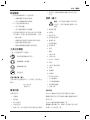
Markings on Tool
The following pictograms are shown on the tool:
Read instruction manual before use.
Wear ear protection.
Wear eye protection.
Bore Diameter.
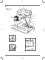
DATE CODE POSITION (FIGURE 1)
The date code (v), which also includes the year of
manufacture, is printed into the housing.
Example:
2010 XX XX
Year of Manufacture
Package Contents
The package contains:
1 Chopsaw
1 Cutting disc
1 Hex key
1 Instruction manual
• Checkfordamagetothetool,partsor
accessories which may have occurred during
transport.
• Takethetimetothoroughlyreadand
understand this manual prior to operation.
Description (Figure 1)
WARNING: Never modify the power
tool or any part of it. Damage or
personal injury could result.
a. On/off switch
b. Padlock hole
c. Operating handle
d. Lock-on button
e. Carrying handle
f. Depth stop bolt
g. Lock nut
h. Base
i. Fence
j. Material clamp
k. Cutting table
l. 8 mm hex key
m. Handle
n. Material clamp lever
o. Cutting disc
p. Guard
q. Spindle lock
r. Lock-down hook
s. Spark deflector
t. Spark deflector screw
u. Lock-down chain
v. Date code
INTENDED USE
Your D28710 chop saw has been designed for the
cutting of variously shaped steel materials.
DO NOT use under wet conditions or in presence of
flammable liquids or gases.
The D28710 chop saw is a professional power tool.
DO NOT let children come into contact with the
tool. Supervision is required when inexperienced
operators use this tool.
7

ENGLISH
Electrical Safety
The electric motor has been designed for one
voltage only. Always check that the power supply
corresponds to the voltage on the rating plate.
Your DeWALT tool is double insulated;
therefore no earth wire is required.
If the supply cord is damaged, it must be replaced
by a specially prepared cord available through
theDeWALT service organisation.
Using an Extension Cable
If an extension cable is required, use an approved
3–core extension cable suitable for the power input of
this tool (see Technical Data).The minimum conductor
size is 1.5 mm
2
; the maximum length is 30 m.
When using a cable reel, always unwind the cable
completely.
Connecting to the Mains
The mains supply to be used for this machine must
be equipped with a 16 A cut-out fuse with time delay.
Voltage Drops
Inrush currents cause short-time voltage drops.
Under unfavourable power supply conditions, other
equipment may be affected.
If the system impedance of the power supply is lower
than 0.11 Ω, disturbances are unlikely to occur.
ASSEMBLY AND ADJUSTMENTS
Warning: To reduce the risk of
injury, turn unit off and disconnect
machine from power source before
installing and removing accessories,
before adjusting or changing setups
or when making repairs. Besurethe
triggerswitchisintheOFFposition.An
accidental start-up can cause injury.
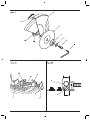
Removing and Fitting a Cutting Disc
(Figure 1, 2)
1. With the arm in the rest position, use the lip (w)
to slide the guard (p) back. Leave the guard
retracted (Figure 2).
2. Press and hold down the spindle lock (q) (Figure
1).
3. Rotate the cutting disc (o) until it locks.
4. Using the hex key (l), remove the bolt (x) by
turning counterclockwise and then remove the
flat washer (y) and the retaining flange (z) (figure
2).
5. Check that the spacer (aa) is in place against
the flange (bb).
6. Replace the cutting disc (o). Make sure that the
new disc is placed onto the spacer (aa) in the
correct rotational direction.
7. Secure the blade with the retaining flange (z),
the flat washer (y) and the bolt (x).
8. Move the guard back down and release the
spindle lock (q).
9. Adjust the cutting depth as necessary.
Adjusting the cutting depth (Figure
1)
The cutting depth can be adjusted to meet the wear
of the cutting disc.
• Makeadryrunwiththetoolswitchedoffand
check for clearance.
• Ifadjustmentisrequired,proceedasfollows:
– Loosen the lock nut (g) a few turns.
– Turn the depth stop bolt (f) in or out as to
achieve the required cutting depth.
– Tighten the lock nut (g).
WARNING: Always adjust the depth
stop to its original position when
replacing the cutting disc.
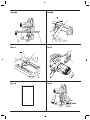
Mounting (Figure 6, 7)
CAUTION: Tool must be supported
on stable, level, non-skid surface
to prevent unexpected movement
when operating.PROCEDURE FOR
PERMANENT MOUNTING
1. Drill two holes 5/16” (8 mm) through the work
surface (Figure 6).
2. Insert 1/4–20 screws down through the holes
in the base and through holes in mounting
surface. The approximate length of the screws
should be the thickness of the mounting surface
plus 4” (102 mm).
CRADLE MOUNTING (FIGURE 7)
1. Cut two boards approximately 20” long x 2”
high x 4” wide (508 x 50.8 x 101.6mm).
2. Place the chop saw at desired work location.
3. Place boards tightly alongside and nail to work
surface.
8

ENGLISH
Clamping the Workpiece in Position
(Figure 1, 3)
The tool is equipped with a material clamp (j) (Figure
1).
1. Pull the lever (n) toward the handle (m) (Figure
3A).
2. Push the clamp shaft (cc) forward until the jaw
(dd) is almost touching the workpiece.
3. Press the lever (n) toward the jaw (dd) until it
engages with the clamp shaft (cc).
4. Rotate the handle (m) clockwise and clamp the
workpiece securely.
5. To release the workpiece, rotate the handle (m)
counterclockwise.
WARNING:
•Toincreasethecuttingcapacity,
place a spacer block (ee) under the
workpiece (ff). The spacer block
should be slightly narrower than the
workpiece(Figure3B).
•Supportlongworkpiecesusinga
piece of wood (gg) (Figure 3C). Do
not clamp the cut off end (hh).
QUICK TRAVEL FEATURE (FIGURE 3A)
The clamp has a quick travel feature.
To release the clamp, rotate the handle (m) one or
two turns counterclockwise and pull the lever (n)
toward the handle (m).
SETTING THE CLAMPING POSITION (FIGURE 3D)
The clamping position can be set to match the
cutting disc.
1. Remove the fence bolts (ii) using the hex key (l).
2. Move the fence (i) as required.
3. Re-fit the fence bolts (ii) and tighten them to
lock the fence (i).
Adjusting the Angle of Cut (Figure 4)
The tool can be used for mitre cuts up to 45°.
1. Loosen the fence bolts (ii) to release the fence (i).
2. Set the fence (i) to the required angle. The angle
can be read on the scale (jj).
3. Tighten the fence bolts (ii) to lock the fence (i).
Checking and Adjusting the Mitre
Scale (Figure 1, 4)
1. Loosen the fence bolts (ii) to release the fence (i)
(Figure 4).
2. Pull down the arm and lock it in this position
using the lock-down chain (u) (Figure 1).
3. Place a square (kk) against the fence (i) and the
left side of the cutting disc creating a perfect
90° (figure 4). Check that the 0° marking on the
scale (jj) aligns with the marking on the table (ll).
4. Tighten the fence bolts (ii) to lock the fence (i).
5. Release the lock-down chain (u) and return the
arm to its upper rest position (Figure 1).
Adjusting the Spark Deflector (Figure
1)
1. Loosen the screw (t).
2. Set the spark deflector (s) as appropriate.
3. Tighten the screw (t).
Prior to Operation
• Installtheappropriatecuttingdisc.Donotuse
excessively worn discs. The maximum rotation
speed of the tool must not exceed that of the
cutting disc.
• Makesurethediscrotatesinthedirectionof
the arrows on the accessory and the tool.
• Securetheworkpiece.
• Alwayssetthesparkdeectorcorrectly.
OPERATION
Instructions for Use
WARNING:
•Alwaysobservethesafetyinstructions
and applicable regulations.
•Donotapplyexcessivepressureto
the tool.
•Avoidoverloading.Shouldthetool
become hot, let it run a few minutes
under no-load condition.
WARNING: To reduce the risk
of serious personal injury, turn
tool off and disconnect tool from
power source before making any
adjustments or removing/installing
attachments or accessories.
Proper Hand Position (Figure 5)
WARNING: To reduce the risk of
serious personal injury, ALWAYS use
proper hand position as shown.
9

ENGLISH
WARNING: To reduce the risk of
serious personal injury, ALWAYS hold
securely in anticipation of a sudden
reaction.
Proper hand position requires one hand on the
operating handle (c), with the other hand guiding the
workpiece.
Performing a Cut (Figure 1)
1. Place the material to be cut against the fence (i)
and secure using the material clamp (j).
2. Turn the tool on and pull down the operating
handle (c) to cut the workpiece. Allow the motor
to reach full speed before cutting.
3. Allow the disc to cut freely. Do not force.
4. After completing the cut, switch off the tool and
return the arm to its upper rest position.
Switching On and Off (Figure 1)
The on/off switch (a) is mounted in the operating
handle (c).
To run the tool, press the on/off switch (a).
Keep the on/off switch depressed while performing
the operation.
To stop the tool, release the switch.
The tool can be locked on for continuous use
by depressing the on/off switch (a) and then by
depressing the lock-on button (d). Hold the lock-on
button (d) as the on/off switch (a) is gently released.
To turn the tool off from the locked on position,
squeeze the on/off switch (a) and the lock-on button
(d) is released.
Do not unplug the tool with the switch locked on.
Make sure the tool is not locked on when plugging
in.
WARNING: Do not switch the tool on
or off when under load.
WARNING: Do not cut magnesium.
Transporting (Figure 1)
The tool is equipped with a lock-down chain (u)
which locks the tool in closed-down position for
carrying.
1. Lower the guard (p) onto the cutting table (k)
and secure the tool in this position by hooking
the chain (u) over the lock-down hook (r).
2. Transport the tool using the carrying handle (e).
To release the tool, depress the operating handle (c)
slightly and release the chain.
MAINTENANCE
Your DeWALT power tool has been designed to
operate over a long period of time with a minimum
of maintenance. Continuous satisfactory operation
depends upon proper tool care and regular cleaning.
WARNING: To reduce the risk of
injury, turn unit off and disconnect
machine from power source before
installing and removing accessories,
before adjusting or changing set-
ups or when making repairs. Besure
thetriggerswitchisintheOFFposition.
An accidental start-up can cause injury.
Lubrication
Your power tool requires no additional lubrication.
Cleaning
WARNING:Blowdirtanddustoutof
the main housing with dry air as often as
dirt is seen collecting in and around the
air vents. Wear approved eye protection
and approved dust mask when
performing this procedure.
WARNING: Never use solvents or
other harsh chemicals for cleaning the
non-metallic parts of the tool. These
chemicals may weaken the materials
used in these parts. Use a cloth
dampened only with water and mild
soap. Never let any liquid get inside the
tool; never immerse any part of the tool
into a liquid.
Optional Accessories
WARNING: Since accessories, other
than those offered by DeWALT, have
not been tested with this product,
use of such accessories with this tool
could be hazardous. To reduce the risk
of injury, only DeWALT recommended
accessories should be used with this
product.
10

ENGLISH
Consult your dealer for further information on the
appropriate accessories.
Protecting the Environment
Separate collection. This product
must not be disposed of with normal
household waste.
Should you find one day that your DeWALT product
needs replacement, or if it is of no further use to you,
do not dispose of it with household waste. Make this
product available for separate collection.
Separate collection of used products and
packaging allows materials to be recycled
and used again. Re-use of recycled
materials helps prevent environmental
pollution and reduces the demand for
raw materials.
Local regulations may provide for separate collection
of electrical products from the household, at
municipal waste sites or by the retailer when you
purchase a new product.
DeWALT provides a facility for the collection and
recycling of DeWALT products once they have
reached the end of their working life. To take
advantage of this service please return your product
to any authorised repair agent who will collect them
on our behalf.
You can check the location of your nearest
authorised repair agent by contacting your local
DeWALT office at the address indicated in this
manual. Alternatively, a list of authorised DeWALT
repair agents and full details of our after-sales
service and contacts are available on the Internet at:
www.2helpU.com.
11

D28710
电压
伏
220
频率
赫兹
50
输入功率
瓦
2200
空载速度
分
-1
3,800
切割片
最小线速度
米/秒
80
切割片直径
毫米
355
切割片孔径 毫米
25.4
切割片厚度
毫米
3.1
切割片类型
直线,无凹槽
90度角横切能力
圆形 毫米
100
正方形 毫米
100 x 100
长方形 毫米
95 x 120
角形 毫米
125 x 125
45度角横切能力
圆形
毫米
100
正方形
毫米
95 x 95
长方形
毫米
95 x 105
角形
毫米
100 x 100
重量 公斤
16.6
D28710
感谢您选择得伟工具
。
凭借多年的经验和产品开
发及创新方面的不断努力
,
得伟已经成功跻身于
专业电动工具用户的最可靠伙伴之一
。
表示的情形,
如不加以阻止,导致。
表示有触电危险。
表示火灾危险。
为降低伤害风险,请阅读
使用手册。
不遵循下列的警告和守则可能会导致
触电、火灾和/或严重伤害。
警告中的术语“电动工具”是指电源驱动(有线)
电动工具,或者电池驱动(充电)电动工具。
1)
a)
混乱或黑暗的
场地会引发事故。
b)
不要在易燃液体、气体或粉尘等存在的易
爆环境中操作电动工具。电动工具产生的
火花会点燃粉尘或气体。
c)
分心会使你放松控制。
2)
a)
未经改装的插头和
相配的插座将减少触电危险。
b)
如果您的身体接地会
增加触电危险。
c)
水进入电动工具将增加触电危险。
下列定义解释了各标志术语的严重程度
。
请仔细
阅读本手册并注意这些标志
。
表示紧急的危险情形,如不加
以阻止,导致。
表示潜在的危险情形,如不加
以阻止,导致。
表示潜在的危险情形,如不加
以阻止,导致。
12

d)
受损或缠绕的
电线会增加触电危险。
e)
适合户外使用的电线将减
少触电危险。
f)
RCD
使用
RCD
可降低
触电危险。
3)
a)
操作电动工具期间精力分散会导致严重
人身伤害。
b)
安全装
置,诸如适当条件下的防尘面具、防滑安
全鞋、安全帽或听力保护等装置能减少
人身伤害。
c)
手指放在开关上
搬运电动工具,或开关处于接通状态时
插入插头均可引发危险。
d)
遗留在电动工具旋转零件上的扳手
可能会导致人身伤害。
e)
这样在意外情况下才能更好地控制
电动工具。
f)
宽松衣服、佩饰或长发可能会卷入运动
部件。
g)
使用这些装置可减少粉尘引起的
危险。
4)
a)
选用设计额值的适当电动
工具会让您更有效、更安全地执行工作。
b)
不能用开关来控制的电动工具是
危险的且必须进行修理。
c)
这种防护性措施将降低电动工具意外
启动的风险。
d)
电动
工具在未经培训的用户手中会发生危险。
e)
许多事故原
因都是电动工具电瓶不良。
f)
保养良好、切削锋
利的刀具不易卡住而且更易于控制。
g)
电动工具用于设计之外的目的时,可能发
生危险。
5)
a)
这将确保电动工具的
安全性。
•
操作该工具时请戴普通工作手套。
•
保持双手远离切割片。请勿切割需要在距
离旋转的切割片15厘米范围内进行手动操
作的加工件。
•
请勿使用该工具提供的切割片切割厚度小
于1.2毫米的加工件。
•
请勿在没有防护的情况下操作该工具。
13

•
请勿空手进行任何操作。使用材料夹钳夹
稳加工件。
•
禁止把手伸到切割片的后面。
•
请把该工具放置于平坦稳定的平面上,该
平面应该维护良好,没有砸碎材料,如碎
片和切屑等。
•
使用之前,请检查切割片是否有裂缝或
缺陷。如果有裂缝或缺陷,请丢弃该切
割片。
•
确保切割片在机器开启之前不接触加
工件。
•
操作中,避免撞击切割片或粗暴对待切割
片。如果出现这种情况,请停止操作工具
并检查切割片。
•
请勿站在与切割片并列的位置操作该工
具。让其他人员远离工作区。
•
小心切割碎片和被切割材料。它们可能会
很热且很锋利。处理切割下来的部件前请
先让它们冷却。
•
火花挡板使用过程中会变热。避免操作后
立即触摸或调整火花挡板。
•
移动加工件或更改设置前,请断开工具的
电源,等待切割片停止后再进行操作。
•
切断电源后,请勿尝试通过按住圆盘侧面
来停止切割片。
•
请勿使用润切液。润切液可能会被点燃或
导致电击。
•
请检查加工件已正确支撑。
•
请使用厂商推荐的切割片。
•
切割片的最大允许速度必须始终大于或等
于标示牌上标明的工具空载速度。
•
此工具上不能使用圆锯片或任何其他锯齿
片。 这样可能造成严重伤害。
•
请勿使用不符合技术资料说明的切割片。
•
使用前,确保正确安装和紧固研磨切
割片。
•
阅读锯轮制造商提供的操作说明。
•
请让工具在空载情况下在安全的位置运作
至少30秒。如果有较大振动或出现任何其
他缺陷,请停止刀具并检查确定其原因。
•
请勿使用切割片来进行侧磨。
•
请勿切割混凝土、砖头、瓦片或陶瓷材料。
•
请勿切割木头、塑料或合成材料。
•
请勿切割铸铁材料。
•
禁止切割镁材料。
•
请勿切割带电材料。
•
请在通风良好的地区使用工具。请勿在可
燃液体、气体或粉尘附近使用该工具。切
割或弧形电动机刷子产生的火花或热的碎
片可能会点燃易燃材料。
•
在多粉尘环境下工作时,要经常清除通风
口。清除通风口时,请记住先拔掉工具的
电源。
•
请把切割片存放在保护条件好和干燥的地
方,避免儿童够及。
•
如果发现机器故障,包括防护装置或切割
片故障,应立即报告。
•
只能使用最大厚度3.1毫米
和最大直径355毫米的切割
锯轮。
使用该工具会产生包含致癌、
导致不育或其他生殖性疾病的化学
成分的粉尘。请使用适当的呼吸保护
措施。
•
在切割操作前始终正确固定加工件。应通
过适合的附加工作台、锯木架或滚子台支
撑超过1.0米的工件米的加工件。
•
关闭机器后,要考虑到锯轮会继续旋转。
•
为防止失去控制,请始终使用螺丝夹或
长度和强度足够的螺栓,将工具固定到工
作台。
以下因素影响噪音的产生
:
–
所要切割的材料。
–
切割片的种类。
–
进刀力度。
请采取适当措施保护听力。
14

•
使用该机器固有以下风险:
–
触摸正在旋转部件导致的伤害。
–
切割片破裂导致的伤害。
•
这些风险在下列情况最为明显:
–
在工作区域范围内。
–
在旋转机器部件的范围内。
•
即使应用了相关的安全规则和安全设施,某些
残余风险仍无法避免。这些残余风险包括:
–
听力的损伤。
–
旋转切割片暴露部分引发的事故风险。
–
更换切割片时的受伤风险。
–
打开护罩时挤压手指的风险。
本工具上有下列图形
:
使用前阅读使用手册
。
请佩戴听力保护器
。
请佩戴护目装备
。
孔径
。
1
包含制造年份的日期码(
v
)印在工具外壳上
。
例如
:
2011 XX XX
制造年份
该产品套装包括:
1
部切割机
1
张切割片
1
个内六角扳手
1
本操作说明书
•
请仔细查看工具、部件和配件是否在运输途
中有所损伤。
•
使用工具前,请耐心阅读、细心理解本手册。
1
切勿修改本电动工具或其任何
部件。否则,可能造成人身伤害或
工具损坏。
a.
开关
b.
挂锁孔
c.
操作手柄
d.
锁定按钮
e.
搬运手柄
f.
限深器螺栓
g.
锁紧螺母
h.
底座
i.
挡板
j.
材料夹具
k.
切割台
l. 8
毫米内六角扳手
m.
夹具手柄
n.
控制杆
o.
切割片
p.
护罩
q.
主轴锁
r.
锁销
s.
火花挡板
t.
火花挡板螺钉
u.
锁定链
v.
日期码
您购买的
D28710
切割机用于各种形状的钢铁材料
的切割
。
在潮湿或存在易燃液体
、
气体的环境中使用
本工具
。
D28710
切割锯是专业电动工具
。
让儿童接触本工具
。
无使用经验的人必须在
监督下使用
。
15

该电机只有一种工作电压。请确认电源电压同标
牌上标明的电压一致。
得伟工具为双重绝缘,因此不需要
地线。
如果电源线损坏,必须采用得伟维修机构提供的
专用线。
如果需要使用延长电缆
,
请使用符合该工具的输入
功率
(
参见
)
的经认证
3
芯延长线
。
导线
最小横截面积为
1.5
平方毫米
,
最大长度为
30
米
。
使用线缆卷筒时,应将线缆完全松开。
该机器使用的电源必须配备带延时功能的
16
安培
保险装置
。
启动电流将导致短时压降。
在供电不好的情况下,其他设备可能会受到影响。
如果系统的电源电阻小于0.11 Ω
,可能不会出现
干扰。
请确保
触发开关处于
OFF
位置。意外启动容
易造成人身伤害。
1
2
1. 让机头处于停止位置
,
利用边缘(
w
)把护罩(
p
)
往回滑动
。
保持护罩处于回缩状态(
Figure 2
)
。
2.
按住主轴锁(
q
) (
Figure 1
)
。
3.
旋转切割片(
o
)直到其锁定
。
4.
使用内六角扳手(
l
)
,
反时针方向旋转
,
松开
螺丝(
x
)
,
然后取下平垫圈
(
y
)和固定法兰(
z
)
(
Figure 2
)
。
5.
检查确保垫圈(
aa
)紧靠在法兰(
bb
)
。
6.
更换切割片
(
o
)
。
确保放在垫圈
(
aa
)上的新圆盘
的旋转方向正确
。
7.
使用固定法兰(
z
)
、
平垫圈
(
y
)和螺钉(
x
)固定住
刀片
。
8.
往下移动护罩到原来位置
,
然后松开主轴锁(
q
)
。
9.
根据需要调整切割深度
。
1
切割深度可以根据切割片的磨损程度来调整
。
• 在工具断电的情况下试运行
,
检查其间距
。
• 如果需要调整
,
继续以下步骤
:
– 松开锁紧螺母(
g
)几圈
。
– 向内或向外扭动限深器螺栓(
f
)
,
得到所需
的切割深度
。
– 拧紧锁紧螺母(
g
)
。
更换切割片时,要把限深器调
整到其初始位置。
6
7
1. 穿过工作表面钻两个
5/16
”
(
8
毫米
)
的孔
(
Figure 6
)
。
2.
将
1/4–20
螺钉穿过底座中的孔
,
然后穿过安
装表面中的孔
。
螺钉的长度大约是安装表面
的厚度加
4
”
(
102
毫米
)。
7
1. 裁切两块大约
20
”长
x 2
”高
x 4
”宽
(
508 x
50.8 x 101.6
毫米
)
的板
。
2.
将切割锯放在所需的工作位置
。
3.
将板子紧贴在旁边
,
然后用钉子钉在工作
表面上
。
16

1
3
该工具配备有一个材料夹具(
j
) (
Figure 1
)
。
1.
向夹具手柄(
m
)方向拉动控制杆(
n
) (
Figure 3A
)
。
2.
向前推动夹具轴
(
cc
)直到夹钳(
dd
)几乎接触加
工件
。
3.
向夹钳
(
dd
)方向推动控制杆(
n
)
,
直到它与夹
具轴(
cc
)绞合
。
4.
顺时针旋转夹具手柄
(
m
)
,
稳固地夹紧加工件
。
5.
如果要松开加工件
,
逆时针旋转夹具手柄(
m
)
。
•
如果要增加切割能力,在加工件(ff)
的下面放置一个垫块(ee)。垫块应
该比加工件稍窄(Figure 3B)。
•
使用木块(gg)来支撑较长的加工
件(Figure 3C)。请勿夹住切割下来
的一端(hh)。
夹钳有快速移动功能
。
要松开夹钳
,
逆时针方向旋转夹具手柄(
m
)一到
两圈
,
然后向夹具手柄(
m
)方向拉动控制杆(
n
)
。
可以设置夹紧位置
,
以便与切割片相匹配
。
1.
使用内六角扳手
(
l
)卸下挡板螺钉(
ii
)
。
2.
根据要求移动挡板(
i
)
。
3.
重新装上挡板螺钉
(
ii
)
,
拧紧锁定挡板
(
i
)
。
4
该工具可以用于高达45度的斜角切割。
1.
拧松挡板螺钉(
ii
)
,
松开挡板
(
i
)
。
2.
设定挡板(
i
)到所需角度
。
该角度可以在标尺(
jj
)
上读取
。
3.
拧紧挡板螺钉(
ii
)
,
锁定挡板
(
i
)
。
1
4
1.
拧松挡板螺钉
(
ii
)
,
松开挡板
(
i
) (
Figure 4
)
。
2.
拉下机头
,
按入锁定链(
u
)把它锁定在该位置
(
Figure 1
)
。
3.
放置一个直角尺(
kk
)在挡板(
i
)和切割片左侧之
间
,
以建立一个精确的
90
度直角(
Figure 4
)
。
检查保证标尺(
jj
)上的
0
度标记与底座(
ll
)上的标
记对齐
。
4.
拧紧挡板螺钉
(
ii
)
,
锁定挡板
(
i
)
。
5.
拔出锁定链(
u
)
,
然后把机头推回其上方的停
止位置(
Figure 1
)
。
1
1.
松开螺丝(
t
)
。
2.
把火花挡板
(
s
)调整到适当位置
。
3.
拧紧螺丝
(
t
)
。
•
安装合适的切割片
。
不要使用过度磨损的切
割片
。
工具最大的旋转速度不能超过切割片
的速度
。
• 确认切割片按照配件和工具上所示箭头的方
向旋转
。
• 固定住加工件
。
• 始终正确设置火花挡板
。
•
请务必遵守安全说明和相关适用
规则。
•
请勿给工具施加过大压力。
•
避免过载作业。 如果工具过热,
请让该工具空载运作几分钟。
5
为降低严重的人身伤害风险,
使用正确的手部位置,如图所示。
17

为降低严重的人身伤害风险,
紧握工具预防意外事件。
正确的手部位置要求一只手握住操作手柄(
c
)
,
另一只手则引导加工件
。
1
1.
紧靠挡板
(
i
)放置好需要切割的材料
,
使用夹钳
(
j
)固定好
。
2.
接通工具的电源
,
拉下操作手柄(
c
)对加工件
进行切割
。
切割前应使电机达到全速
。
3.
让切割片自由切割
。
请勿加力
。
4.
切割完毕后
,
切断工具的电源
,
把机头推回
其上方的停止位置
。
1
电源开关(
a
)安装在操作手柄(
c
)上
。
运行工具
,
请按启
/
闭开关(
a
)
。
操作时
,
保持启
/
闭开关处于下压状态
。
要停止工具
,
松开开关
。
通过按下开关(
a
)然后按锁定按钮(
d
)
,
可锁定
工具以连续使用
。
开关(
a
)缓慢释放时按住锁定
按钮(
d
)
。
要从锁定位置关闭工具
,
请压下开关(
a
)
,
锁定
按钮(
d
)松开
。
开关锁定时不要拔下工具的插头
。
插入插头时
确保工具没有锁定
。
工具加载时,请勿开启或关掉
工具。
请勿切割镁材料。
1
该工具配备一个锁定链(
u
)
,
可以在运输时把工具
锁定在固定位置
。
1.
把护罩
(
p
)降低到底座(
k
)上
,
然后按入锁定链(
u
)
在锁销(
r
)上
,
把工具固定在该位置上
。
2.
使用搬运手柄
(
e
)运送工具
。
要放开工具
,
轻轻压下操作手柄(
c
)
,
然后拔出
锁定链
。
您购买的得伟电动工具经过精心设计
,
具有寿命
长
、
维修简易的特点
。
持续理想的运作性能依赖
于妥善保养和经常清洁
。
请确保
触发开关处于OFF位置。意外启动容
易造成人身伤害。
您购买的电动工具无须额外的润滑
。
一旦通风口及其周围积聚可见
的粉尘,请即用干燥的压缩空气吹走
主机外壳内的粉尘和灰尘。进行这一
步骤时,请佩戴经认可的护目装备和
认可的面罩。
切勿使用溶剂或其它刺激性化
学品来清洁工具的非金属部件。这些
化学品可能削弱零件中使用的材料。
只能使用抹布蘸中性肥皂水进行清
洁。勿使任何液体进入工具;勿使
工具的任何部分浸入液体中。
由于非得伟附件未经本产品
匹配测试,本工具若使用此类附件,
将存在隐患。为降低人身伤害风险,
本产品仅可使用得伟推荐的附件。
请向零售商咨询合适附件的更多信息
。
18
ページが読み込まれています...
ページが読み込まれています...
ページが読み込まれています...
ページが読み込まれています...
ページが読み込まれています...
ページが読み込まれています...
ページが読み込まれています...
ページが読み込まれています...
ページが読み込まれています...
ページが読み込まれています...
ページが読み込まれています...
ページが読み込まれています...
ページが読み込まれています...
ページが読み込まれています...
ページが読み込まれています...
ページが読み込まれています...
ページが読み込まれています...
ページが読み込まれています...
ページが読み込まれています...
ページが読み込まれています...
-
 1
1
-
 2
2
-
 3
3
-
 4
4
-
 5
5
-
 6
6
-
 7
7
-
 8
8
-
 9
9
-
 10
10
-
 11
11
-
 12
12
-
 13
13
-
 14
14
-
 15
15
-
 16
16
-
 17
17
-
 18
18
-
 19
19
-
 20
20
-
 21
21
-
 22
22
-
 23
23
-
 24
24
-
 25
25
-
 26
26
-
 27
27
-
 28
28
-
 29
29
-
 30
30
-
 31
31
-
 32
32
-
 33
33
-
 34
34
-
 35
35
-
 36
36
-
 37
37
-
 38
38
-
 39
39
-
 40
40


