
SF SERIES
™
HIGH PERFORMANCE SFX POWER SUPPLY
MANUAL • MANUEL • MANUALE • MANUELLE • MANUAL DE
РУКОВОДСТВО • MANUAL • MANUELL • 用户手册 • 取扱説明書
SF600
SF450
SF750
SF SERIES
™
WEB: corsair.com
PHONE: (888) 222-4346
SUPPORT: support.corsair.com
BLOG: corsair.com/blog
FORUM: forum.corsair.com
YOUTUBE: youtube.com/corsairhowto
© 2010-2018 CORSAIR MEMORY, Inc. All rights reserved.
CORSAIR and the sails logo are registered trademarks in the United States
and/or other countries. All other trademarks are the property of their respective
owners. Product may vary slightly from those pictured. 49-001769 AA

English
Français
Deutsch
Italiano
Español
Россию
Português
Svenska
中文
日本語

1 2
SF SERIES
™
SF SERIES
™
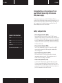
PRODUCTSPECIFICATIONS
SF ....................................................
SF ....................................................
SF ....................................................
Installation ...........................................
ImportantSafetyInformation .........
Congratulations on the purchase of your
new CORSAIR Series High Performance
SFX power supply.
SF Series power supplies give you 80 PLUS Platinum eciency,
excellent electrical performance, and virtually silent operation in a SFX
form factor. With 105°C Japanese capacitors and Zero RPM fan mode,
they’re a great choice for high performance small form factor PC’s
where reliability and low noise are essential.
Safety and protection
• Over-voltage protection (OVP)
Over-voltage protection for the 12V, 5V and 3.3V DC outputs is
required to comply with the SFX specification. OVP shuts down the
PSU in the event that the DC outputs exceed a set level, determined
by the PSU manufacturer. The minimum voltage levels required for
compliance are 13.4V for the +12V rail(s), 5.74V for the +5V rail and
3.76V for the 3.3V rail.
• Over-current protection (OCP)
The SF Series features OCP on the 3.3V, 5V and 12V rails. OCP
ensures that the output of the DC voltage rails remains within
safe operating limits.
• Over-temperature protection (OTP)
OTP ensures that the PSU will shut down when the internal
temperature reaches a set point. This is usually as a result of
internal current overloading or a fan failure.
• Short-circuit protection (SCP)
A short-circuit is defined as any output impedance of less than
0.1 ohms. Amongst other things, SCP ensures that the PSU shuts
down should the 3.3V, 5V and 12V rails short to any other rail, or to
ground. It also ensures that no damage should occur to the unit, or
your PC’s components in the event of a short.

3 4
SF SERIES
™
SF SERIES
™
Qty Description Total Length
1
ATX Cable 24 pin
Connectors per cable
300mm
(± 10mm)
1
Total connectors
1
2
EPS/ATX12V 8 pin (4+4) cable
Connectors per cable
400mm
(± 10mm)
1
Total connectors
2
2
PCIe 8 pin (6+2) cable
Connectors per cable
500mm
(± 10mm)
2
Total connectors
4
2
SATA cable (4 SATA)
Connectors per cable
445mm
(± 10mm)
4
Total connectors
8
1
Peripheral cable (4-pin)
Connectors per cable
330mm
(± 10mm)
3
Total connectors
3
0 75
0
150 300 450 600
35
30
25
20
15
10
5
0
95
93
91
89
87
85
83
81
100
10
5020
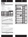
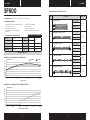
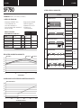
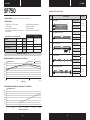
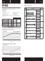
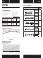
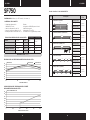
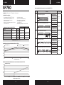
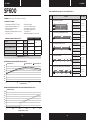
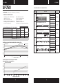
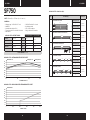
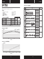
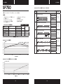
CORSAIR SF750 POWER TABLE
MAX LOAD MAX OUTPUT
MODEL RPS0115 +3.3V 20A
130W
PART NO. CP-9020186 +5V 20A
AC INPUT RATING 100–240V +12V 62.5A 750W
INPUT CURRENT 10A–5A -12V 0.3A 3.6W
FREQUENCY 47–63Hz +5Vsb 2.5A 12.5W
TOTAL POWER: 750W
SF750
CORSAIR SF750 POWER SUPPLY EFFICIENCY
input 115VAC input 230VACEFFICIENCY (%)
SYSTEM LOAD (%)
CORSAIR SF750 POWER SUPPLY FAN NOISE CURVE
FAN NOISE (db)
POWER OUTPUTS (WATTS)
CORSAIR SF750 DC CABLE LISTING
450mm 100mm 100mm
100mm 115mm 115mm
550mm 100mm 100mm 100mm
100mm 115mm 115mm 115mm
650mm
400mm
610mm
300mm
400mm
100mm
DIMENSIONS: 125mm (W) x 63.5 mm (H) x 100mm (L)
PACKAGE CONTENTS:
• CORSAIR SF Series power supply unit
• AC power cord
• DC modular cable set
• DC modular cable storage bag
• Cable ties
• CORSAIR case badge
• User manual
• SFX to ATX adapter
• Important safety information

5 6
SF SERIES
™
SF SERIES
™
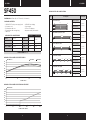
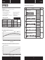
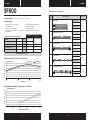
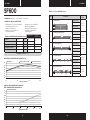
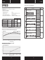
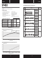
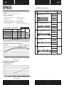
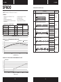
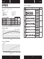
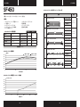
CORSAIR SF600 POWER TABLE
MAX LOAD MAX OUTPUT
MODEL RPS0112 +3.3V 20A
120W
PART NO. CP-9020182 +5V 20A
AC INPUT RATING 100–240V +12V 50A 600W
INPUT CURRENT 10A–5A -12V 0.3A 3.6W
FREQUENCY 47–63Hz +5Vsb 2.5A 12.5W
TOTAL POWER: 600W
Qty Description Total Length
1
ATX Cable 24 pin
Connectors per cable
300mm
(± 10mm)
1
Total connectors
1
1
EPS/ATX12V 8 pin (4+4) cable
Connectors per cable
400mm
(± 10mm)
1
Total connectors
1
2
PCIe 8 pin (6+2) cable
Connectors per cable
400mm
(± 10mm)
1
Total connectors
2
1
SATA cable (4 SATA)
Connectors per cable
445mm
(± 10mm)
4
Total connectors
4
1
Peripheral cable (4-pin)
Connectors per cable
330mm
(± 10mm)
3
Total connectors
3
CORSAIR SF600 DC CABLE LISTING
450mm 100mm 100mm
100mm 115mm 115mm
550mm 100mm 100mm 100mm
100mm 115mm 115mm 115mm
650mm
400mm
610mm
300mm
600mm
400mm
SF600
0 60
0
120 240 360 480
35
30
25
20
15
10
5
0
95
93
91
89
87
85
83
81
100
10
5020
CORSAIR SF600 POWER SUPPLY EFFICIENCY
input 115VAC input 230VACEFFICIENCY (%)
SYSTEM LOAD (%)
CORSAIR SF600 POWER SUPPLY FAN NOISE CURVE
FAN NOISE (db)
POWER OUTPUTS (WATTS)
DIMENSIONS: 125mm (W) x 63.5 mm (H) x 100mm (L)
PACKAGE CONTENTS:
• CORSAIR SF Series power supply unit
• AC power cord
• DC modular cable set
• DC modular cable storage bag
• Cable ties
• CORSAIR case badge
• User manual
• SFX to ATX adapter
• Important safety information

7 8
SF SERIES
™
SF SERIES
™
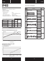
SF450
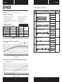
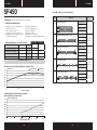
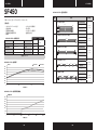
CORSAIR SF450 DC CABLE LISTING
CORSAIR SF450 POWER TABLE
MAX LOAD MAX OUTPUT
MODEL RPS0111 +3.3V 15A
100W
PART NO. CP-9020181 +5V 20A
AC INPUT RATING 100–240V +12V 37.5A 450W
INPUT CURRENT 10A–5A -12V 0.3A 3.6W
FREQUENCY 47–63Hz +5Vsb 2.5A 12.5W
TOTAL POWER: 450W
Qty Description Total Length
1
ATX Cable 24 pin
Connectors per cable
300mm
(± 10mm)
1
Total connectors
1
1
EPS/ATX12V 8 pin (4+4) cable
Connectors per cable
400mm
(± 10mm)
1
Total connectors
1
2
PCIe 8 pin (6+2) cable
Connectors per cable
400mm
(± 10mm)
1
Total connectors
2
1
SATA cable (4 SATA)
Connectors per cable
445mm
(± 10mm)
4
Total connectors
4
1
Peripheral cable (4-pin)
Connectors per cable
330mm
(± 10mm)
3
Total connectors
3
450mm 100mm 100mm
100mm 115mm 115mm
550mm 100mm 100mm 100mm
100mm 115mm 115mm 115mm
650mm
400mm
610mm
300mm
600mm
400mm
0 45
0
90 180 270 360
35
30
25
20
15
10
5
0
95
93
91
89
87
85
83
81
100
10
5020
CORSAIR SF450 POWER SUPPLY EFFICIENCY
input 115VAC input 230VACEFFICIENCY (%)
SYSTEM LOAD (%)
CORSAIR SF450 POWER SUPPLY FAN NOISE CURVE
FAN NOISE (db)
POWER OUTPUTS (WATTS)
DIMENSIONS: 125mm (W) x 63.5 mm (H) x 100mm (L)
PACKAGE CONTENTS:
• CORSAIR SF Series power supply unit
• AC power cord
• DC modular cable set
• DC modular cable storage bag
• Cable ties
• CORSAIR case badge
• User manual
• SFX to ATX adapter
• Important safety information

9 10
SF SERIES
™
SF SERIES
™
Installing your NEW SF Series
Step A: Removing your existing power supply
If you are building a new system, skip to Step B.
1. Disconnect the AC power cord from your wall outlet or UPS and
from the existing power supply.
2. Disconnect all the power cables from your video card,
motherboard and all other peripherals.
3. Follow the directions in your chassis manual and uninstall your
existing power supply.
4. Proceed to Step B.
Step B: Installing the CORSAIR SF Series power supply
1. Make sure the power supply’s AC power cable is not connected.
2. Follow the directions in your chassis manual and install the power
supply with the screws provided.
3. Connect the 24-pin main power cable from the power supply
directly to your motherboard.
4. Connect the eight-pin +12V (EPS12V) cable to the motherboard.
A. If your motherboard has an eight-pin +12V socket, connect the
eight-pin cable directly to your motherboard.
B. If your motherboard has a four-pin socket, detach the
four-pin from the eight-pin cable, and then plug this four-pin
cable directly to your motherboard.
5. Connect the peripheral cables, PCI-Express cables, and SATA cables.
A. Connect the peripherals cables to your hard drive and
CD-ROM/DVD-ROM power sockets.
B. Connect the SATA cables to your SATA SSD or hard drive’s
power sockets.
C. Connect the PCI-Express cables to the power sockets of your
PCI-Express video cards if required.
D. Connect the peripheral cables to any peripherals requiring
a small 4-pin connector.
E. Make sure all the cables are tightly connected. Be sure to save
any unused modular cables for future component additions.
6. Connect the AC power cord to the power supply and turn it on by
pushing the switch to the ON position (marked with “I”).

11 12
SF SERIES
™
SF SERIES
™
Important safety information
CAUTION ELECTRIC SHOCK HAZARD!
1. Install in accordance with all manufacturer instructions and safety
warnings. Failure to do so may result in damage to your power
supply or system, and may cause serious injury or death.
2. High voltages are present in the power supply. Do not open the
power supply case or attempt to repair the power supply; there are
no user-serviceable components.
3. This product is designed for indoor use only.
4. Do not use the power supply near water, or in high temperature or
high humidity environments.
5. Do not install near any heat sources such as radiators, heat
registers, stoves, or other apparatus that produce heat.
6. Do not insert any objects into the open ventilation or fan grill area
of the power supply.
7. Do not modify the cables and/or connectors included with this
power supply.
8. If this power supply uses modular cables, use only manufacturer
supplied cables. Other cables might not be compatible and could
cause serious damage to your system and power supply.
9. The 24-pin main power connector has a detachable 4-pin
connector. This 4-pin connector is not a P4 or ATX 12V
connector. Do not force this cable in the P4 or ATX +12V socket
on the motherboard.
10. Failure to comply with any manufacturer instructions and/or any
of these safety instructions will immediately void all warranties
and guarantees.
Zero RPM mode
Zero RPM mode allows the fan to remain o during low to medium
loads. This technology uses various temperatures from inside the PSU
and the power output level to determine when active cooling is needed
for the PSU. When you’re pushing it hard the fan will turn itself on to
ensure that it gets the cooling it needs without any extra noise. For
the specific fan profile of your unit please refer to the specifications
section of that PSU.

13 14
SF SERIES
™
SF SERIES
™
SPÉCIFICATIONSDUPRODUIT
SF ..................................................
SF ..................................................
SF ..................................................
Installation .........................................
ConsignesdeSécurité
importantes .......................................
Nous vous remercions d’avoir acheté
l’alimentation SFX haute performance
de la gamme CORSAIR.
Les alimentations SF Series assurent une ecacité 80 PLUS Platinum,
d’excellentes performances électriques et un fonctionnement presque
silencieux dans un facteur de forme SFX. Grâce aux condensateurs
japonais de 105°C et au mode de ventilation Zero RPM, elles sont
idéales pour les ordinateurs performants de petite taille pour lesquels
la fiabilité et le faible bruit sont primordiaux.
Sécurité et protection
• Protection contre la surtension (OVP)
La conformité à la spécification SFX requiert une protection
contre la surtension au niveau des sorties CC 12V 5V et 3.3V.
Cette protection coupe l’alimentation lorsque les sorties CC
dépassent un seuil établi, déterminé par le constructeur de
l’alimentation. Les niveaux de tension minimum requis pour la
conformité sont de 13.4V pour le ou les rails +12V 5.74V pour le
rail +5V et 3.76V pour le rail 3.3V.
• Protection contre les surintensités (OCP)
Les rails 3.3V 5V et 12V des alimentations SF Series disposent d’une
protection contre les surintensités (OCP). Cette protection garantit
que la sortie en tension des rails CC s’inscrit dans les limites d’une
exploitation sûre.
• Protection contre les surchaues (OTP)
La protection contre les surchaues (OTP) garantit que
l'alimentation s'arrête lorsque sa température interne atteint un
seuil défini. Cette situation résulte généralement d'une surcharge
électrique interne ou de la défaillance du ventilateur.
• Protection contre les courts-circuits (SCP)
Un court-circuit se définit par toute impédance de sortie inférieure
à 0.1ohm. Entre autres opérations, la fonction SCP s'assure que
l'alimentation s'arrête si les rails 3.3V 5V et 12V entrent en court-
circuit les uns avec les autres ou avec la masse. La fonction SCP
garantit également qu’en cas de court-circuit, l’unité ainsi que les
composants de votre PC ne subissent aucun dommage.

15 16
SF SERIES
™
SF SERIES
™
TABLEAU DE PUISSANCE
DE L’ALIMENTATION CORSAIR SF750
CHARGE MAXI
SORTIE MAXI
MODÈLE RPS0115 +3.3V 20A
130W
RÉFÉRENCE PIÈCE CP-9020186 +5V 20A
ENTRÉE CA NOMINALE 100–240V +12V 62.5A 750W
COURANT EN ENTRÉE 10A–5A -12V 0.3A 3.6W
FRÉQUENCE 47–63Hz +5Vsb 2.5A 12.5W
PUISSANCE TOTALE: 750W
Qté Description
Longueur
totale
1
Câble ATX 24broches
Connecteurs par câble
300mm
(± 10mm)
1
Total des connecteurs
1
2
Câble EPS/ATX12V 8 broches (4+4)
Connecteurs par câble
400mm
(± 10mm)
1
Total des connecteurs
2
2
Câble PCIe 8 broches (6+2)
Connecteurs par câble
500mm
(± 10mm)
2
Total des connecteurs
4
2
Câble SATA (4 SATA)
Connecteurs par câble
445mm
(± 10mm)
4
Total des connecteurs
8
1
Câble périphérique (4 broches)
Connecteurs par câble
330mm
(± 10mm)
3
Total des connecteurs
3
LISTE DES CÂBLES CC CORSAIR SF750
450mm 100mm 100mm
100mm 115mm 115mm
550mm 100mm 100mm 100mm
100mm 115mm 115mm 115mm
650mm
400mm
610mm
300mm
SF750
DIMENSIONS: 125mm (I) x 63.5 mm (H) x 100mm (L)
CONTEN U DE L’EMBALLAGE:
• Alimentation CORSAIR SF Series
• Cordon d’alimentation CA
• Jeu de câbles modulaires CC
• Sac de stockage de câbles modulaires CC
• Attaches de câbles
• Badge de boîtier CORSAIR
• Manuel de l’utilisateur
• Adaptateur SFX vers ATX
• Informations de
sécurité importantes
0 75
0
150 300 450 600
35
30
25
20
15
10
5
0
95
93
91
89
87
85
83
81
100
10
5020
EFFICACITÉ DE L’ALIMENTATION CORSAIR SF750
EFFICACITÉ (%)
CHARGE SYSTÈME (%)
COURBE SONORE DU VENTILATEUR DE L’ALIMENTATION CORSAIR SF750
BRUIT DU VENTILATEUR (db)
PUISSANCE EN SORTIE (WATTS)
Entrée 115VCA
Entrée 230VCA
400mm
100mm

17 18
SF SERIES
™
SF SERIES
™
TABLEAU DE PUISSANCE
DE L’ALIMENTATION CORSAIR SF600
CHARGE MAXI
SORTIE MAXI
MODÈLE RPS0112 +3.3V 20A
120W
RÉFÉRENCE PIÈCE CP-9020182 +5V 20A
ENTRÉE CA NOMINALE 100–240V +12V 50A 600W
COURANT EN ENTRÉE 10A–5A -12V 0.3A 3.6W
FRÉQUENCE 47–63Hz +5Vsb 2.5A 12.5W
PUISSANCE TOTALE: 600W
Qté Description
Longueur
totale
1
Câble ATX 24broches
Connecteurs par câble
300mm
(± 10mm)
1
Total des connecteurs
1
1
Câble EPS/ATX12V 8 broches (4+4)
Connecteurs par câble
400mm
(± 10mm)
1
Total des connecteurs
1
2
Câble PCIe 8 broches (6+2)
Connecteurs par câble
400mm
(± 10mm)
1
Total des connecteurs
2
1
Câble SATA (4 SATA)
Connecteurs par câble
445mm
(± 10mm)
4
Total des connecteurs
4
1
Câble périphérique (4 broches)
Connecteurs par câble
330mm
(± 10mm)
3
Total des connecteurs
3
LISTE DES CÂBLES CC CORSAIR SF600
450mm 100mm 100mm
100mm 115mm 115mm
550mm 100mm 100mm 100mm
100mm 115mm 115mm 115mm
650mm
400mm
610mm
300mm
600mm
400mm
SF600
0 60
0
120 240 360 480
35
30
25
20
15
10
5
0
95
93
91
89
87
85
83
81
100
10
5020
EFFICACITÉ DE L’ALIMENTATION CORSAIR SF600
EFFICACITÉ (%)
CHARGE SYSTÈME (%)
COURBE SONORE DU VENTILATEUR DE L’ALIMENTATION CORSAIR SF600
BRUIT DU VENTILATEUR (db)
PUISSANCE EN SORTIE (WATTS)
Entrée 115VCA
Entrée 230VCA
DIMENSIONS: 125mm (I) x 63.5 mm (H) x 100mm (L)
CONTEN U DE L’EMBALLAGE:
• Alimentation CORSAIR SF Series
• Cordon d’alimentation CA
• Jeu de câbles modulaires CC
• Sac de stockage de câbles modulaires CC
• Attaches de câbles
• Badge de boîtier CORSAIR
• Manuel de l’utilisateur
• Adaptateur SFX vers ATX
• Informations de
sécurité importantes

19 20
SF SERIES
™
SF SERIES
™
SF450
LISTE DES CÂBLES CC CORSAIR SF450
Qté Description
Longueur
totale
1
Câble ATX 24broches
Connecteurs par câble
300mm
(± 10mm)
1
Total des connecteurs
1
1
Câble EPS/ATX12V 8 broches (4+4)
Connecteurs par câble
400mm
(± 10mm)
1
Total des connecteurs
1
2
Câble PCIe 8 broches (6+2)
Connecteurs par câble
400mm
(± 10mm)
1
Total des connecteurs
2
1
Câble SATA (4 SATA)
Connecteurs par câble
445mm
(± 10mm)
4
Total des connecteurs
4
1
Câble périphérique (4 broches)
Connecteurs par câble
330mm
(± 10mm)
3
Total des connecteurs
3
450mm 100mm 100mm
100mm 115mm 115mm
550mm 100mm 100mm 100mm
100mm 115mm 115mm 115mm
650mm
400mm
610mm
300mm
600mm
400mm
TABLEAU DE PUISSANCE
DE L’ALIMENTATION CORSAIR SF450
CHARGE MAXI
SORTIE MAXI
MODÈLE RPS0111 +3.3V 15A
100W
RÉFÉRENCE PIÈCE CP-9020181 +5V 20A
ENTRÉE CA NOMINALE 100–240V +12V 37.5A 450W
COURANT EN ENTRÉE 10A–5A -12V 0.3A 3.6W
FRÉQUENCE 47–63Hz +5Vsb 2.5A 12.5W
PUISSANCE TOTALE: 450W
0 45
0
90 180 270 360
35
30
25
20
15
10
5
0
95
93
91
89
87
85
83
81
100
10
5020
EFFICACITÉ DE L’ALIMENTATION CORSAIR SF450
EFFICACITÉ (%)
CHARGE SYSTÈME (%)
COURBE SONORE DU VENTILATEUR DE L’ALIMENTATION CORSAIR SF450
BRUIT DU VENTILATEUR (db)
PUISSANCE EN SORTIE (WATTS)
Entrée 115VCA
Entrée 230VCA
DIMENSIONS: 125mm (I) x 63.5 mm (H) x 100mm (L)
CONTEN U DE L’EMBALLAGE:
• Alimentation CORSAIR SF Series
• Cordon d’alimentation CA
• Jeu de câbles modulaires CC
• Sac de stockage de câbles modulaires CC
• Attaches de câbles
• Badge de boîtier CORSAIR
• Manuel de l’utilisateur
• Adaptateur SFX vers ATX
• Informations de
sécurité importantes

21 22
SF SERIES
™
SF SERIES
™
Installation de votre NOUVELLE
alimentation SF Series
Étape A: Retrait de l'alimentation existante
Si vous assemblez un nouveau système, passez directement
à l'étape B.
1. Déconnectez le cordon d’alimentation CA de la prise muraleou de
votre onduleur, puis de toute unité d’alimentation présente.
2. Déconnectez tous les câbles d’alimentation de vos périphériques
(carte vidéo, carte mère, etc.).
3. Suivez les instructions du manuel de votre châssis et désinstallez
votre alimentation existante.
4. Passez à l'étape B.
Étape B: Installation de l’alimentation
CORSAIR SF Series
1. Assurez-vous que le câble d’alimentation CA de l’unité
est déconnecté.
2. Suivez les instructions du manuel de votre châssis et installez
l’alimentation au moyen des vis fournies.
3. Raccorder le câble d’alimentation principal à 24 broches de l’unité
d’alimentation directement à votre carte mère.
4. Raccordez le câble +12V (EPS12V) à 8broches à la carte mère.
A. Si votre carte mère dispose d'un connecteur +12V à 8broches,
raccordez le câble à 8broches directement à celle-ci.
B. Si votre carte mère dispose d'un connecteur à 4broches,
détachez le module à 4broches du câble à 8broches, puis
raccordez directement le câble à 4broches ainsi obtenu à la
carte mère.
5. Raccordez les câbles des périphériques, les câbles PCI-Express
et les câbles SATA.
A. Raccordez les câbles des périphériques aux prises
d'alimentation de vos disques durs et lecteurs de
CD-ROM/DVD-ROM.
B. Raccordez les câbles SATA aux prises d'alimentation de vos
disques mécaniques et SSD SATA.
C. Raccordez les câbles PCI-Express aux prises d'alimentation de
vos cartes vidéo PCI-Express (le cas échéant).
D. Raccordez les câbles des périphériques aux éventuels
périphériques requérant un petit connecteur à 4broches.
E. Assurez-vous que tous les câbles sont fermement raccordés.
Veillez à conserver tout câble modulaire inutilisé pour un
éventuel ajout de composants ultérieur.
6. Raccordez le cordon d’alimentation CA à l’unité d’alimentation
et mettez celle-ci sous tension en poussant le switch en position
MARCHE (marquée d’un I).

23 24
SF SERIES
™
SF SERIES
™
Consignes de sécurité importantes
ATTENTION! RISQUE DE CHOC ÉLECTRIQUE!
1. Procédez à l’installation conformément à toutes les instructions du
fabricant et à tous les avertissements de sécurité. Le non-respect
de cette condition pourrait conduire à l’endommagement de
votre alimentation ou de votre système, et pourrait engendrer des
blessures graves, voire le décès de l’utilisateur.
2. L’alimentation est le siège de hautes tensions. N’ouvrez pas le
boîtier de l’alimentation et ne tentez pas de la réparer; il ne
contient aucun composant sur lequel l’utilisateur peut intervenir.
3. Ce produit est conçu pour un usage en intérieur uniquement.
4. N'utilisez pas l'alimentation près de l'eau, ni dans des
environnements à température ou à niveau d'hygrométrie élevé.
5. N'installez pas l'alimentation à proximité de sources de chaleur, tels
que radiateurs, registres thermiques, poêles ou autres appareils qui
produisent de la chaleur.
6. N'insérez aucun objet à travers l'ouverture à grille du ventilateur ou
l'évacuation de l'alimentation.
7. Ne modifiez pas les câbles et/ou les connecteurs intégrés
à cette alimentation.
8. Si cette alimentation utilise des câbles modulaires, utilisez
uniquement les câbles fournis par le fabricant. Les autres câbles
peuvent se révéler incompatibles et infliger des dommages
importants à votre système et à votre alimentation.
9. Le connecteur d’alimentation à 24broches principal dispose d’un
connecteur à 4broches amovible. Ce connecteur à 4broches n'est
pas un connecteur P4 ou ATX 12V. N'insérez pas ce câble de force
dans le connecteur P4 ou ATX 12V de la carte mère.
10. Le non-respect des instructions du fabricant et/ou des
présentes consignes de sécurité entraînera l'annulation immédiate
de toute garantie.
Mode Zero RPM
Le mode Zero RPM permet de mettre le ventilateur à l’arrêt pendant
une exploitation en charge faible à moyenne. Cette technologie fait
appel à diérentes valeurs de température internes à l'alimentation et
au niveau de puissance de sortie pour déterminer si un refroidissement
actif de l'alimentation est nécessaire. Et lorsque l'unité est fortement
sollicitée, le ventilateur se met en marche afin de garantir qu'il produit
le refroidissement nécessaire, sans aucun bruit supplémentaire. Si votre
unité présente un profil de ventilateur spécifique, veuillez vous reporter
à la section des spécifications de cette alimentation.

25 26
SF SERIES
™
SF SERIES
™
PRODUKTSPEZIFIKATIONEN
SF ..................................................
SF ..................................................
SF ..................................................
Installation .........................................
WichtigeSicherheitshinweise .........
Wir gratulieren zum Kauf Ihres
neuen SFX-Hochleistungsnetzteils
von CORSAIR.
Die Netzteile der SF Series bestechen durch einen als 80PLUS
Platinum zertifizierten Wirkungsgrad, hervorragende elektrische
Leistung und einen praktisch geräuschlosen Betrieb in einem
SFX-Formfaktor. Mit japanischen 105-Grad-Kondensatoren und einem
Zero RPM-Lüftermodus sind sie eine hervorragende Wahl für sehr
leistungsstarke PCs mit kleinem Formfaktor, für die Zuverlässigkeit und
Geräuscharmut unerlässlich sind.
Sicherheit und Schutz
• Überspannungsschutz (Over-Voltage Protection, OVP)
Für die 12-V-, 5-V- und 3.3-V-DC-Ausgänge ist
Überspannungsschutz erforderlich, um den SFX-Spezifikationen
zu entsprechen. Wenn der DC-Ausgang einen vom Hersteller
des Netzteils festgelegten Pegel überschreitet, schaltet der
OVP das Netzteil aus. Die zur Einhaltung erforderlichen
Mindestspannungspegel sind 13.4V für die +12-V-Schiene (n), 5.74V
für die +5-V-Schiene und 3.76V für die 3.3-V-Schiene.
• Überstromschutz (Over-Current Protection, OCP)
Die SF Series verfügt über OCP auf den 3.3-V-, 5-V- und
12-V-Schienen. Der OCP stellt sicher, dass der Ausgang der DC-
Spannungsschienen innerhalb sicherer Betriebsgrenzen bleibt.
• Überhitzungsschutz
(Over-Temperature Protection, OTP)
OTP stellt sicher, dass sich das Netzteil abschaltet, wenn die
Innentemperatur einen festgelegten Wert überschreitet. Für
gewöhnlich geschieht dies bei interner Stromüberlastung oder bei
einem Lüfterausfall.
• Kurzschlussschutz (Short-Circuit Protection, SCP)
Ein Kurzschluss liegt vor, wenn die Ausgangsimpedanz unter
0.1Ohm liegt. Der SCP garantiert u.a., dass sich das Netzteil
abschaltet, wenn die 3.3-V-, 5-V- und 12-V-Schienen an einer
anderen Schiene einen Kurzschluss oder einen Masseschluss
auslösen. Er schützt darüber hinaus das Gerät und die
Komponenten Ihres PCs im Falle eines Kurzschlusses.

27 28
SF SERIES
™
SF SERIES
™
Menge
Beschreibung
Gesamtlänge
1
ATX, 24Pins
Anschlüsse pro Kabel
300mm
(± 10mm)
1
Anschlüsse insgesamt
1
2
EPS/ATX12V, 8Pins (4+4)
Anschlüsse pro Kabel
400mm
(± 10mm)
1
Anschlüsse insgesamt
2
2
PCIe, 8Pins (6+2)
Anschlüsse pro Kabel
500mm
(± 10mm)
2
Anschlüsse insgesamt
4
2
SATA (4 SATA)
Anschlüsse pro Kabel
445mm
(± 10mm)
4
Anschlüsse insgesamt
8
1
Peripheriekabel (4Pins)
Anschlüsse pro Kabel
330mm
(± 10mm)
3
Anschlüsse insgesamt
3
CORSAIR SF750 DC-Kabelliste
450mm 100mm 100mm
100mm 115mm 115mm
550mm 100mm 100mm 100mm
100mm 115mm 115mm 115mm
650mm
400mm
610mm
300mm
SF750
CORSAIR SF600 Leistungstabelle
HÖCHSTBELASTUNG
MAXIMALE
AUSGANGSLEISTUNG
MODELL RPS0115 +3.3V 20A
130W
TEILENR. CP-9020186 +5V 20A
AC-EINGANGSNENNLEISTUNG 100–240V +12V 62.5A 750W
EINGANGSSTROM 10A–5A -12V 0.3A 3.6W
FREQUENZ 47–63Hz +5Vsb 2.5A 15W
GESAMTLEISTUNG: 750W
ABMESSUNGEN: 125mm (B) x 63.5 mm (H) x 100mm (L)
LIEFERUMFANG:
• CORSAIR SF Series-Netzteil
• AC-Netzkabel
• Modularer DC-Kabelsatz
• Beutel für den modularen DC-Kabelsatz
• Kabelbinder
• CORSAIR-Gehäuseaufkleber
• Benutzerhandbuch
• SFX-ATX-Adapter
• Wichtige sicherheits-hinweise
0 75
0
150 300 450 600
35
30
25
20
15
10
5
0
95
93
91
89
87
85
83
81
100
10
5020
WIRKUNGSGRAD DES CORSAIR SF750 NETZTEILS
WIRKUNGSGRAD (%)
SYSTEMLAST (%)
LÜFTERGERÄUSCHKURVE DES CORSAIR SF750 NETZTEILS
LÜFTERGERÄUSCH (dB)
AUSGANGSLEISTUNG (WATT)
Eingang 115 VAC
Eingang 230 VAC
400mm
100mm

29 30
SF SERIES
™
SF SERIES
™
Menge
Beschreibung
Gesamtlänge
1
ATX, 24Pins
Anschlüsse pro Kabel
300mm
(± 10mm)
1
Anschlüsse insgesamt
1
1
EPS/ATX12V, 8Pins (4+4)
Anschlüsse pro Kabel
400mm
(± 10mm)
1
Anschlüsse insgesamt
1
2
PCIe, 8Pins (6+2)
Anschlüsse pro Kabel
400mm
(± 10mm)
1
Anschlüsse insgesamt
2
1
SATA (4 SATA)
Anschlüsse pro Kabel
445mm
(± 10mm)
4
Anschlüsse insgesamt
4
1
Peripheriekabel (4Pins)
Anschlüsse pro Kabel
330mm
(± 10mm)
3
Anschlüsse insgesamt
3
CORSAIR SF600 DC-Kabelliste
450mm 100mm 100mm
100mm 115mm 115mm
550mm 100mm 100mm 100mm
100mm 115mm 115mm 115mm
650mm
400mm
610mm
300mm
600mm
400mm
SF600
CORSAIR SF600 Leistungstabelle
HÖCHSTBELASTUNG
MAXIMALE
AUSGANGSLEISTUNG
MODELL RPS0112 +3.3V 20A
120W
TEILENR. CP-9020182 +5V 20A
AC-EINGANGSNENNLEISTUNG 100–240V +12V 50A 600W
EINGANGSSTROM 10A–5A -12V 0.3A 3.6W
FREQUENZ 47–63Hz +5Vsb 2.5A 12.5W
GESAMTLEISTUNG: 600W
0 60
0
120 240 360 480
35
30
25
20
15
10
5
0
95
93
91
89
87
85
83
81
100
10
5020
WIRKUNGSGRAD DES CORSAIR SF600 NETZTEILS
WIRKUNGSGRAD (%)
SYSTEMLAST (%)
LÜFTERGERÄUSCHKURVE DES CORSAIR SF600 NETZTEILS
LÜFTERGERÄUSCH (dB)
AUSGANGSLEISTUNG (WATT)
Eingang 115 VAC
Eingang 230 VAC
ABMESSUNGEN: 125mm (B) x 63.5 mm (H) x 100mm (L)
LIEFERUMFANG:
• CORSAIR SF Series-Netzteil
• AC-Netzkabel
• Modularer DC-Kabelsatz
• Beutel für den modularen DC-Kabelsatz
• Kabelbinder
• CORSAIR-Gehäuseaufkleber
• Benutzerhandbuch
• SFX-ATX-Adapter
• Wichtige sicherheits-hinweise

31 32
SF SERIES
™
SF SERIES
™
SF450
Menge
Beschreibung
Gesamtlänge
1
ATX, 24Pins
Anschlüsse pro Kabel
300mm
(± 10mm)
1
Anschlüsse insgesamt
1
1
EPS/ATX12V, 8Pins (4+4)
Anschlüsse pro Kabel
400mm
(± 10mm)
1
Anschlüsse insgesamt
1
2
PCIe, 8Pins (6+2)
Anschlüsse pro Kabel
400mm
(± 10mm)
1
Anschlüsse insgesamt
2
1
SATA (4 SATA)
Anschlüsse pro Kabel
445mm
(± 10mm)
4
Anschlüsse insgesamt
4
1
Peripheriekabel (4Pins)
Anschlüsse pro Kabel
330mm
(± 10mm)
3
Anschlüsse insgesamt
3
CORSAIR SF450 DC-Kabelliste
450mm 100mm 100mm
100mm 115mm 115mm
550mm 100mm 100mm 100mm
100mm 115mm 115mm 115mm
650mm
400mm
610mm
300mm
600mm
400mm
CORSAIR SF450 Leistungstabelle
HÖCHSTBELASTUNG
MAXIMALE
AUSGANGSLEISTUNG
MODELL RPS0111 +3.3V 15A
100W
TEILENR. CP-9020181 +5V 20A
AC-EINGANGSNENNLEISTUNG 100–240V +12V 37.5A 450W
EINGANGSSTROM 10A–5A -12V 0.3A 3.6W
FREQUENZ 47–63Hz +5Vsb 2.5A 12.5W
GESAMTLEISTUNG: 450W
0 45
0
90 180 270 360
35
30
25
20
15
10
5
0
95
93
91
89
87
85
83
81
100
10
5020
WIRKUNGSGRAD DES CORSAIR SF450 NETZTEILS
WIRKUNGSGRAD (%)
SYSTEMLAST (%)
LÜFTERGERÄUSCHKURVE DES CORSAIR SF450 NETZTEILS
LÜFTERGERÄUSCH (dB)
AUSGANGSLEISTUNG (WATT)
Eingang 115 VAC
Eingang 230 VAC
ABMESSUNGEN: 125mm (B) x 63.5 mm (H) x 100mm (L)
LIEFERUMFANG:
• CORSAIR SF Series-Netzteil
• AC-Netzkabel
• Modularer DC-Kabelsatz
• Beutel für den modularen DC-Kabelsatz
• Kabelbinder
• CORSAIR-Gehäuseaufkleber
• Benutzerhandbuch
• SFX-ATX-Adapter
• Wichtige sicherheits-hinweise

33 34
SF SERIES
™
SF SERIES
™
Installation der NEUEN SF Series
SchrittA: Entfernen des alten Netzteils
Wenn Sie ein neues System bauen, fahren Sie mit SchrittB fort.
1. Trennen Sie das AC-Stromkabel von der Steckdose oder der USV
und vom vorhandenen Netzteil.
2. Trennen Sie alle Stromkabel von Ihrer Videokarte, vom Mainboard
und von allen anderen Peripheriekomponenten.
3. Deinstallieren Sie Ihr vorhandenes Netzteil gemäß Anleitung
für Ihr Gehäuse.
4. Fahren Sie mit SchrittB fort.
SchrittB: Installation des CORSAIR SF Series Netzteils
1. Stellen Sie sicher, dass das AC-Stromkabel des Netzteils nicht
angeschlossen ist.
2. Installieren Sie das Netzteil mit den im Lieferumfang enthaltenen
Schrauben laut Gebrauchsanweisung Ihres Gehäuses.
3. 24-polige Hauptstromkabel vom Netzteil direkt mit dem
Motherboard verbinden.
4. Verbinden Sie das 8-polige +12-V-Kabel (EPS12V) mit
dem Mainboard.
A. Wenn Ihr Mainboard über einen 8-poligen +12-V-Sockel verfügt,
können Sie das 8-polige Kabel direkt an Ihr
Mainboard anschließen.
B. Wenn Ihr Mainboard über einen 4-poligen Sockel verfügt,
entfernen Sie die 4-polige Einheit vom 8-poligen Kabel und
verbinden Sie dieses 4-polige Kabel direkt mit dem Mainboard.
5. Schließen Sie die Kabel der Peripheriekomponenten,
die PCI-Express- und SATA-Kabel an.
A. Verbinden Sie die Kabel der Peripheriekomponenten mit den
Stromanschlüssen Ihrer Festplatte und CD-ROM/DVD-ROM.
B. Verbinden Sie die SATA-Kabel mit den Stromanschlüssen Ihrer
SATA SSD oder Festplatte.
C. Schließen Sie gegebenenfalls die PCI-Express-Kabel an die
Stromanschlüsse Ihrer PCI-Express-Videokarte an.
D. Die Kabel der Peripheriekomponenten können Sie an alle
Komponenten anschließen, die einen kleinen 4-poligen
Steckverbinder erfordern.
E. Stellen Sie sicher, dass alle Kabel fest verbunden sind.
Heben Sie nicht verwendete modulare Kabel für den Einbau
zukünftiger Komponenten auf.
6. Schließen Sie das AC-Stromkabel an das Netzteil an, und
schalten Sie den Schalter zum Einschalten in die EIN-Position
(mit „I“ gekennzeichnet).

35 36
SF SERIES
™
SF SERIES
™
Wichtige Sicherheitshinweise
VORSICHT STROMSCHLAGGEFAHR!
1. Befolgen Sie bei der Installation die Anweisungen und
Sicherheitshinweise des Herstellers. Die Nichteinhaltung kann zu
Schäden an Ihrem Netzteil oder System führen und kann schwere
oder tödliche Verletzungen verursachen.
2. Im Netzteil liegen hohe Spannungen an. Önen Sie niemals das
Gehäuse des Netzteils und versuchen Sie nicht, es zu reparieren.
Es gibt dort keine zu wartenden Komponenten.
3. Dieses Produkt ist nur für den Betreb im Innenbereich gedacht.
4. Verwenden Sie das Netzteil nicht in der Nähe von Wasser
oder bei hohen Temperaturen oder in Umgebungen mit
hoher Luftfeuchtigkeit.
5. Stellen Sie das Gerät nicht in der Nähe von Wärmequellen wie
Heizlüftern, Heizungen, Öfen oder anderen Wärme erzeugenden
Geräten auf.
6. Führen Sie keine Gegenstände in die oenen Bereiche der Lüftung
oder Lüftergitter des Netzteils ein.
7. Modifizieren Sie keine Kabel oder Steckverbinder, die im
Lieferumfang dieses Netzteils enthalten sind.
8. Wenn dieses Netzteil modulare Kabel verwendet, verwenden Sie
nur die vom Hersteller bereitgestellten Kabel. Andere Kabel sind
eventuell nicht kompatibel und können zu ernsthaften Schäden an
Ihrem System und Netzteil führen.
9. Der 24-polige Hauptstromstecker hat einen abnehmbaren
4-poligen Steckverbinder. Bei diesem 4-poligen Steckverbinder
handelt es sich nicht um einen P4- oder ATX-+12-V-Steckverbinder.
Schieben Sie dieses Kabel nicht mit Gewalt in den P4- oder ATX
+12-V-Sockel des Mainboards.
10. Nichtbeachtung der Herstelleranweisungen oder einer dieser
Sicherheitshinweise führt zum sofortigen Verlust aller
Gewährleistungs- und Garantieansprüche.
Zero RPM-Modus
Der Zero RPM-Modus ermöglicht, dass der Lüfter bei geringer bis
mittlerer Belastung ausgeschaltet bleibt. Anhand verschiedener
Temperaturen im Inneren des Netzteils und der jeweiligen
Ausgangsleistung erkennt diese Technologie, wann das Netzteil
gekühlt werden muss. Bei hoher Belastung schaltet sich der Lüfter
automatisch ein, um sicherzustellen, dass das Gerät die benötigte
Kühlung ohne zusätzliche Geräuschbelastung erhält. Das spezifische
Lüfterprofil Ihres Gerätes finden Sie im Abschnitt mit den technischen
Daten dieses Netzteils.
ページが読み込まれています...
ページが読み込まれています...
ページが読み込まれています...
ページが読み込まれています...
ページが読み込まれています...
ページが読み込まれています...
ページが読み込まれています...
ページが読み込まれています...
ページが読み込まれています...
ページが読み込まれています...
ページが読み込まれています...
ページが読み込まれています...
ページが読み込まれています...
ページが読み込まれています...
ページが読み込まれています...
ページが読み込まれています...
ページが読み込まれています...
ページが読み込まれています...
ページが読み込まれています...
ページが読み込まれています...
ページが読み込まれています...
ページが読み込まれています...
ページが読み込まれています...
ページが読み込まれています...
ページが読み込まれています...
ページが読み込まれています...
ページが読み込まれています...
ページが読み込まれています...
ページが読み込まれています...
ページが読み込まれています...
ページが読み込まれています...
ページが読み込まれています...
ページが読み込まれています...
ページが読み込まれています...
ページが読み込まれています...
ページが読み込まれています...
ページが読み込まれています...
ページが読み込まれています...
ページが読み込まれています...
ページが読み込まれています...
ページが読み込まれています...
ページが読み込まれています...
-
 1
1
-
 2
2
-
 3
3
-
 4
4
-
 5
5
-
 6
6
-
 7
7
-
 8
8
-
 9
9
-
 10
10
-
 11
11
-
 12
12
-
 13
13
-
 14
14
-
 15
15
-
 16
16
-
 17
17
-
 18
18
-
 19
19
-
 20
20
-
 21
21
-
 22
22
-
 23
23
-
 24
24
-
 25
25
-
 26
26
-
 27
27
-
 28
28
-
 29
29
-
 30
30
-
 31
31
-
 32
32
-
 33
33
-
 34
34
-
 35
35
-
 36
36
-
 37
37
-
 38
38
-
 39
39
-
 40
40
-
 41
41
-
 42
42
-
 43
43
-
 44
44
-
 45
45
-
 46
46
-
 47
47
-
 48
48
-
 49
49
-
 50
50
-
 51
51
-
 52
52
-
 53
53
-
 54
54
-
 55
55
-
 56
56
-
 57
57
-
 58
58
-
 59
59
-
 60
60
-
 61
61
-
 62
62


Corsair CP-9020186-NA 取扱説明書
- カテゴリー
- 電源ユニット
- タイプ
- 取扱説明書
他の言語で
- svenska: Corsair CP-9020186-NA Bruksanvisning
- italiano: Corsair CP-9020186-NA Manuale del proprietario
- español: Corsair CP-9020186-NA El manual del propietario
- Deutsch: Corsair CP-9020186-NA Bedienungsanleitung
- français: Corsair CP-9020186-NA Le manuel du propriétaire
- português: Corsair CP-9020186-NA Manual do proprietário
- English: Corsair CP-9020186-NA Owner's manual
- русский: Corsair CP-9020186-NA Инструкция по применению
