
D SERIES
High-Power installation platform
Rev. 3.0.3
Quick Start Guide
Lake Variants:
D 200:4L
D 120:4L
D 80:4L
D 40:4L
D 20:4L
D 10:4L
Incorporating technologies from
Item no. QSG-DSERIES-LAKE

3
D SERIES Lake Quick Start Guide rev 3.0.3
1. Important safety instructions
2
D SERIES Lake Quick Start Guide rev 3.0.3
1. Important safety instructions
Before using the device, be sure to carefully read the Safety Instructions. Keep this document with the device at
all times.
1. Read these instructions.
2. Keep these instructions
3. Heed all warnings.
4. Follow all instructions.
5. Do not use this apparatus near water.
6. Clean only with a dry cloth.
7. Do not block any ventilation openings. Install in accordance
with the manufacturer’s instructions.
8. Do not install near any heat sources such as radiators, heat
registers, stoves, or other apparatus (including amplifi ers)
that produce heat.
9. Do not defeat the safety purpose of the polarized or
grounding-type plug. A polarized plug has two blades with
one wider than the other. A grounding-type plug has two
blades and a third grounding prong. The wide blade or
the third prong is provided for your safety. If the provided
plug does not fi t into your outlet, consult an electrician for
replacement of the obsolete outlet.
10. Protect the power cord from being walked on or pinched,
particularly at plugs, convenience receptacles, and the point
where they exit from the apparatus.
11. Only use attachments/accessories specifi ed by the
manufacturer.
12. Use only with a cart, stand, tripod, bracket, or table specifi ed
by the manufacturer, or sold with the apparatus. When a
cart is used, use caution when moving the cart/apparatus
combination to avoid injury from tip-over.
13. Unplug this apparatus during lightning storms or when
unused for long periods of time.
14. Refer all servicing to qualifi ed service personnel. Servicing
is required when the apparatus has been damaged in any
way, such as power-supply cord or plug is damaged, liquid
has been spilled or objects have fallen into the apparatus, the
apparatus has been exposed to rain or moisture, does not
operate normally, or has been dropped.
15. Use the mains plug to disconnect the appartus from the
mains.
16. WARNING: To reduce the risk of fi re or electric shock, do not
expose this apparatus to rain or moisture.
17. Do not expose this equipment to dripping or splashing and
ensure that no objects fi lled with liquids, such as vases, are
placed on the equipment.
18. The mains plug of the power supply cord shall remain readily
operable.
19. Do not connect the unit’s output to any other voltage source
such as battery, mains source, or power supply, regardless
of whether the unit is turned on or off.
20. Do not remove the top (or bottom) cover. Removal of the
cover will expose hazardous voltages. There are no user
serviceable parts inside and removal may void the warranty.
21. An experienced user shall always supervise this professional
audio equipment, especially if inexperienced adults or
minors are using the equipment.
22. The US National Differences clause 16.3 requires that
network cables must be fl ame rated VW-1.
2. Approvals
3. Warnings
3.1. Explanation of warning symbols
3.2. Warnings
To prevent electric shock do not remove top or bottom
covers. No user serviceable parts inside, refer servicing to
qualifi ed service personnel.
Français: À prévenir le choc électrique n’enlevez pas les
couvercles. Il n’y a pas des parties serviceable à l’intérieur, tous
reparations doit etre faire par personnel qualifi é seulment.
This equipment conforms to the requirements
of the EMC Directive 2014/30/EU and the
requirements of the Low Voltage Directive
2014/35/EU.
Standards applied: EMC Emission
EN55103-1, E4
EMC Immunity EN55103-2, E5, with S/N
below 1% at normal operation level.
Electrical Safety EN60065, Class I
This equipment is tested and listed according to the
U.S. safety standard ANSI/ UL 60065 and
Canadian safety standard CSA C22.2
NO. 60065. Intertek made the tests and they
are a Nationally Recognized Testing Laboratory
(NRTL).
The lightning bolt triangle is used to
alert the user to the presence of
un-insulated “dangerous voltages”
within the unit’s chassis that may be
of suffi cient magnitude to constitute a
risk of electric shock to humans.
The exclamation point triangle is used to
alert the user to presence of important
operating and service instructions in the
literature accompanying the product.
To completely disconnect this equipment from the AC
mains, disconnect the power supply cord plug from the AC
receptacle. The mains plug of the power supply cord shall
remain readily operable.
Français: Pour démonter complètement l’équipement de
l’alimentation générale, démonter le câble d’alimentation
de son réceptacle. La prise d’alimentation restera aisément
fonctionnelle.
To reduce risk of fi re or electric shock, do not expose this
apparatus to rain or moisture.
Français: Pour réduire les risques d’incendie ou de choc
électrique, n’exposez pas l’appareil à la pluie ou à l’humidité.
Do not expose this system/apparatus to dripping or splashing
and ensure that no objects fi lled with liquids, such as vases,
are placed on the apparatus.
Français: N’exposez pas ce système/appareil au
ruissellement ni aux éclaboussures et assurez-vous qu’aucun
objet contenant du liquide tel qu’un vase n’est placé sur
l’appareil.
This apparatus must be connected to a mains socket outlet
with a protective earthing connection.
Français: Cet appareil doit être raccordé à une prise secteur
avec terre de protection.
The mains plug is used as a disconnect device and shall
remain readily operable.
Français: Lorsque la prise du réseau d’alimentation est utilisés
comme dispositif de déconnexion, ce dispositif doit
demeuré aisément accessible.
3.3. Caution
To reduce the risk of fi re or electric shock, do not remove screws.
No user-serviceable parts inside. Refer servicing to qualifi ed
service personnel.
Français: Pour réduire le risque d’incendie ou de choc
électrique, ne pas retirer les vis. Aucune pièce réparable par
l’utilisateur. Confi er l’entretien àpersonnel qualifi é.
3.4. User responsibility
3.4.1. Mains connection grounding
Your amplifi er must be connected to a grounded socket outlet.
3.4.2. Speaker output hazard on amplifi ers
Amplifi ers are capable of producing hazardous output
voltages. To avoid electrical shock, do not touch any exposed
speaker wiring while the amplifi er is operating. The external
wiring connected to the speaker terminals shall be installed
by a qualifi ed person, or ready-made leads or cords of
appropriate capacity shall be used.
As the power output channels on amplifi ers produce high
voltage, do not connect or disconnect speaker cables when
the mains power is on.
3.4.3. Radio interference
A sample of this product has been tested and complies with
the limits for the European Electro Magnetic Compatibility
(EMC) directive. This equipment has also been tested and
found to comply with the limits for a Class A digital device,
pursuant to Part 15 of the FCC Rules. These limits are
designed to provide reasonable protection against harmful
interference from electrical equipment. This product uses
radio frequency energy and if not used or installed in
accordance with these operating instructions, may cause
interference to other equipment, such as radio receivers.
However, there is no guarantee that interference will not
occur in a particular installation. If this equipment does cause
harmful interference to radio or television reception, which
can be determined by turning the equipment on and off, the
user is encouraged to try to correct the interference by one or
more of the following measures:
• Reorient or relocate the antenna.
• Increase the separation between the equipment and
receiver.
• Connect the equipment to an outlet on a circuit different
from that to which the receiver is connected.
• Check if the affected unit complies with the EMC limits for
immunity, (CE-labeled). If not, address the problem with
the manufacturer or supplier. All electrical products sold
in the EC must be approved for immunity against
electromagnetic fi elds, high voltage fl ashes, and radio
interference.
• Consult the dealer or an experienced radio/TV technician
for help.
3.4.4. Speaker damage
Amplifi er apparatus is very powerful and can be potentially
dangerous to both loudspeakers and humans alike. Many
loudspeakers can be easily damaged or destroyed by
overpowering them. Always check the speaker’s continuous
and peak power capabilities. Although the amplifi ers
attenuators can be used to reduce the overall gain, an
increase of the input signal can result in full output power,
which may cause damage to connected speakers.
3.4.5. Maintenance
For safe and reliable operation, the dust fi lters on both sides
of the front panel, behind the grilles, should be removed and
cleaned regularly to ensure maximum airfl ow through the
device.
If the dust fi lters are not maintained there will be safety
risks; for example, high internal temperatures could ignite
the dust and start a fi re. There is also a risk that the unit
will malfunction since it is dependent on constant airfl ow
from front to rear. If the dust fi lters are not clean and the unit
malfunctions, any resulting problems will not be covered by
the warranty.
3. Warnings
This Class A digital apparatus complies with Canadian ICES-003.
Cet appareil numérique de la classe A est conforme à la norme NMB-003
du Canada.

4 5
D SERIES Lake Quick Start Guide rev 3.0.3
D SERIES Lake Quick Start Guide rev 3.0.3
2014/30/EUEMC
2014/35/EU
EN55103-1, E4
EN55103-2, E5,

6 7
D SERIES Lake Quick Start Guide rev 3.0.3
D SERIES Lake Quick Start Guide rev 3.0.3
1.
1.
1.
2.
3.
4.
5.
6.
7.
8.
9.
10 .
11.
12 .
13 .
14.
15.
16.
17.
18 .
19 .
20.
21.
22. US National Differences
16. 3 VW-1
2.
3.
3.1
!
3.2
Français
: À prévenir le choc électrique n’enlevez pas les couvercles. Il n’y a
pas des parties serviceable à l’intérieur, tous reparations doit etre faire par
personnel qualPÄé seulment.
EMC European Electro-Magnetic Com-
patibility: EU 2014/30/EU
2014/35/EU
: EMC
EMC EN55103-2, E5
S/N 1 %
EN60065, I
ANSI/UL 60065
CSA C22.2 NO. 60065
NRTL Nationally
Recognized Testing Laboratory:
Intertek
EN55103-1, E4
Français
: Pour démonter complètement l’équipement de l’alimentation
générale, démonter le câble d’alimentation de son réceptacle. La prise
d’alimentation restera aisément fonctionnelle.
Français:
Pour réduire les risques d’incendie ou de choc électrique,
n’exposez pas l’appareil à la pluie ou à l’humidité.
Français
: N’exposez pas ce système/appareil au ruissellement ni aux
éclaboussures et assurez-vous qu’aucun objet contenant du liquide tel
qu’un vase n’est placé sur l’appareil.
Français:
Cet appareil doit être raccordé à une prise secteur avec terre de
protection.
Français:
Lorsque la prise du réseau d’alimentation est utilisés comme
dispositif de déconnex
ion, ce dispositif doit
demeuré aisément accessible.
3.3
Français
: Pour réduire le risque d’incendie ou de choc électrique, ne pas
retirer les vis. Aucune pièce réparable par l’utilisateur. ConÄer l’entretien
àpersonnel qualPÄé.
3.4
3.4.1
3.4.2
3.4.3
European Electro Magnetic Compatibility EMC directive
FCC
Part 15 Class B
•
•
•
• EMC
CE
EC
•
3.4.4
3.4.5
This Class A digital apparatus complies with Canadian ICES-003.
Class
A ICES-003
Cet appareil
numérique de la classe A est conforme à la norme NMB-003 du Canada.
3.

8 9
D SERIES Lake Quick Start Guide rev 3.0.3
D SERIES Lake Quick Start Guide rev 3.0.3
1. Instructions de sécurité importantes
3. Avertissements
1. Instructions de sécurité importantes
Avant d'utiliser l'appareil, veillez à lire attentivement les instructions de sécurité. Conservez constamment ce
document avec l'appareil.
1. Lisez ces instructions.
2. Conservez ces instructions.
3. Tenez compte de tous les avertissements.
4. Suivez toutes les instructions.
5. N’utilisez pas cet appareil avec de l’eau à proximité.
6. Ne nettoyez l’appareil qu’avec un chiffon sec.
7. N’obstruez aucune ouverture de ventilation. Installez l’unité
conformément aux instructions du fabricant.
8. Ne l’installez pas à proximité de sources de chaleur telles que
des radiateurs, bouches de chaleur, poêles ou autres appareils (y
compris des amplifi cateurs) qui dégagent de la chaleur.
9. Ne neutralisez pas la fonction de sécurité de la fi che polarisée
ou de terre. Une fi che polarisée a deux broches, l’une plus large
que l’autre. Une fi che de terre a deux broches identiques et une
troisième broche pour la mise à la terre. La broche plus large ou
la troisième broche servent à votre sécurité. Si la fi che fournie
n’entre pas dans votre prise, consultez un électricien pour le
remplacement de la prise obsolète.
10. Évitez de marcher sur le cordon d’alimentation et de le pincer, en
particulier au niveau des fi ches, des prises secteur, et du point de
sortie de l’appareil.
11. N’utilisez que des fi xations/accessoires spécifi és par le fabricant.
12. Utilisez-le uniquement avec un chariot, socle, trépied, support
ou table spécifi é par le fabricant ou vendu avec l’appareil. Si
un chariot est utilisé, faites attention à ne pas être blessé par
un renversement lors du déplacement de l’ensemble chariot/
appareil.
13. Débranchez cet appareil en cas d’orage ou de non utilisation
prolongée.
14. Confi ez toute réparation à des techniciens de maintenance
qualifi és. Une réparation est nécessaire si l’appareil a été
endommagé d’une quelconque façon, par exemple si le cordon
ou la fi che d’alimentation est endommagé, si du liquide a été
renversé sur l’appareil ou si des objets sont tombés dedans, si
l’appareil a été exposé à la pluie ou à l’humidité, s’il ne fonctionne
pas normalement, ou s’il est tombé.
15. Utilisez la fi che d’alimentation électrique pour débrancher
l’appareil du secteur.
16. AVERTISSEMENT : pour réduire le risque d’incendie et de choc
électrique, n’exposez pas cet appareil à la pluie ni à l’humidité.
17. N’exposez pas cet appareil au ruissellement ni aux éclaboussures
et n’y posez pas d’objets remplis de liquide comme par exemple
des vases.
18. La fi che secteur du cordon d’alimentation doit toujours rester
facilement accessible.
19. Ne branchez pas la sortie de l’unité à une autre source de tension
telle qu’une batterie, une prise secteur ou une alimentation
électrique, que l’unité soit ou non allumée.
20. Ne retirez pas le capot du dessus (ou du dessous). Retirer le
capot exposera à l’air libre des tensions dangereuses. Aucune
pièce n’est réparable par l’utilisateur à l’intérieur et l’ouverture peut
invalider la garantie.
21. Un utilisateur chevronné doit toujours superviser cet équipement
audio professionnel, particulièrement si des adultes inexpérimen-
tés ou des mineurs utilisent l’équipement.
22. Aux USA, la clause 16.3 des US National Differences exige une
classe d’infl ammabilité VW-1 pour les câbles réseau.
2. Certifi cations
3. Avertissements
3.1. Explication des symboles d’avertissement
3.2. Avertissements
Pour éviter les chocs électriques, ne retirez pas les capots du
dessus et du dessous. Aucune pièce interne n’est réparable
par l’utilisateur, confi ez toute réparation à des techniciens de
maintenance qualifi és.
.
Cet équipement se conforme aux
spécifi cations de la directive CEM sur la
compatibilité électromagnétique 2014/30/EU
et de la directive basse tension 2014/35/EU.
Normes appliquées :
Émission EN55103-1, E4
Immunité EN55103-2, E5, avec rapport signal/
bruit < 1 % au niveau de fonctionnement
normal.
Sécurité électrique EN60065, Classe I
Cet équipement a été testé et référencé à la
norme de sécurité ANSI/UL 60065 pour les
USA et CSA C22.2 N° 60065 pour le Canada.
Les tests ont été effectués par Intertek, un
laboratoire de test à agrément national (NRTL).
Le symbole d’éclair à tête de fl èche dans
un triangle équilatéral sert à prévenir
l’utilisateur de la présence dans l’enceinte
du produit d’une « tension dangereuse » non
isolée suffi sante pour constituer un risque
d’électrocution pour les personnes.
Le point d’exclamation dans un triangle
équilatéral sert à prévenir l’utilisateur de
la présence d’instructions importantes de
fonctionnement et de maintenance (entretien)
dans les documents accompagnant
l’appareil.
Pour totalement isoler l’équipement de l’alimentation secteur,
débranchez le cordon d’alimentation de son embase. La fi che
secteur du cordon d’alimentation doit rester accessible.
Pour réduire les risques d’incendie et de choc électrique,
n’exposez pas cet appareil à la pluie ou à l’humidité.
N’exposez pas ce système/appareil au ruissellement ni aux
éclaboussures et assurez-vous qu’aucun objet contenant du
liquide, tel qu’un vase, n’est placé sur l’appareil.
Cet appareil doit être raccordé à une prise secteur avec terre
de protection.
La fi che d’alimentation sert de dispositif de déconnexion et
doit rester constamment accessible.
3.3. Attention
Pour réduire le risque d’incendie et de choc électrique, ne
retirez pas les vis. Aucune pièce interne n’est réparable par
l’utilisateur. Confi ez toute réparation à des techniciens de
maintenance qualifi és.
3.4. Responsabilité de l’utilisateur
3.4.1. Mise à la terre de la prise secteur
Votre amplifi cateur doit être connecté à une prise de terre.
3.4.2. Danger aux sorties pour enceintes des
amplifi cateurs
Les amplifi cateurs sont capables de produire des tensions
de sortie dangereuses. Pour éviter tout choc électrique, ne
touchez aucun fi l d’enceinte nu quand l’amplifi cateur est en
service. Le câble externe connecté aux borniers d’enceintes
doit être préparé par une personne qualifi ée, sinon des
cordons tout prêts de capacité appropriée doivent être
utilisés.
Comme les canaux de sortie de puissance des amplifi cateurs
produisent une tension élevée, les câbles d’enceintes ne
doivent pas être branchés ou débranchés quand l’appareil est
sous tension.
3.4.3. Interférences radioélectriques
Un échantillon de ce produit a été testé et déclaré conforme
aux limites fi xées par la Directive européenne sur la
compatibilité électromagnétique (CEM). Cet équipement a
aussi été testé et trouvé conforme aux limites fi xées pour
un appareil numérique de Classe A par la partie 15 de la
réglementation FCC. Ces limites sont conçues pour assurer
une protection raisonnable contre les interférences nuisibles
causées par des appareils électriques. Ce produit utilise
des ondes radioélectriques et, s’il n’est pas installé et utilisé
conformément à ces instructions d’utilisation, peut causer
des interférences avec d’autres appareils, tels que les
radiorécepteurs.
L’absence d’interférences n’est toutefois pas garantie pour
une installation donnée. Si cet équipement provoque des
interférences nuisibles à la réception de la radio ou de la
télévision, ce qui peut être déterminé en allumant et en
éteignant l’équipement, l’utilisateur est encouragé à essayer
de corriger les interférences en prenant une ou plusieurs des
mesures suivantes :
• Réorienter ou déplacer l’antenne.
• Augmenter l’espace séparant l’équipement du récepteur.
• Brancher l’équipement à une prise d’un circuit différent de
celui auquel est branché le récepteur.
• Vérifi er si l’unité concernée est conforme aux limites de
CEM pour l’immunité (étiquetage CE). Sinon, résolvez
le problème avec le fabricant ou le fournisseur. Tous les
produits électriques vendus en UE doivent avoir une
immunité certifi ée contre les champs électromagnétiques,
les surtensions, et les interférences radioélectriques.
• Consulter le revendeur ou un technicien radio/TV
expérimenté pour obtenir de l’aide.
3.4.4. Dommages causés aux enceintes
Un amplifi cateur est très puissant et peut être potentiellement
dangereux à la fois pour les enceintes et pour les êtres
humains. De nombreuses enceintes peuvent être facilement
endommagées ou détruites si on les soumet à une puissance
excessive. Vérifi ez toujours les puissances admissibles par
l’enceinte, en continu et en crête. Bien que des atténuateurs
d’amplifi cateurs puissent être utilisés pour réduire le gain
général, une augmentation du signal d’entrée peut conduire
à une sortie à pleine puissance risquant d’endommager les
enceintes connectées.
3.4.5. Entretien
Pour un fonctionnement sûr et fi able, les fi ltres à poussière,
des deux côtés de la face avant derrière les grilles, doivent
être retirés et nettoyés régulièrement afi n d’assurer une
circulation maximale de l’air au travers de l’appareil.
Ne pas entretenir les fi ltres à poussière entraîne des risques
pour la sécurité ; par exemple, une surchauffe interne peut
amener la poussière à s’enfl ammer, déclenchant un incendie.
Il existe également un risque de mauvais fonctionnement de
l’unité car celle-ci nécessite un débit d’air constant de l’avant
vers l’arrière. Si les fi ltres à poussière ne sont pas propres et
si l’appareil ne fonctionne pas correctement, les problèmes
qui en résultent ne sont pas couverts par la garantie.
This Class A digital apparatus complies with Canadian ICES-003.
Cet appareil numérique de la classe A est conforme à la norme NMB-003
du Canada.

10 11
D SERIES Lake Quick Start Guide rev 3.0.3
D SERIES Lake Quick Start Guide rev 3.0.3
3. Warnungen
1. Wichtige Sicherheitshinweise
1. Wichtige Sicherheitshinweise
Lesen Sie bitte diese Sicherheitsanweisungen sorgfältig, bevor Sie das Gerät verwenden. Bewahren Sie dieses Dokument
bitte jederzeit zusammen mit dem Gerät auf.
1. Bitte lesen Sie diese Anweisungen.
2. Bitte bewahren Sie diese Anweisungen auf.
3. Beachten Sie alle Warnhinweise.
4. Folgen Sie bitte allen Anweisungen.
5. Verwenden Sie dieses Gerät nicht in der Nähe von Wasser.
6. Reinigen Sie das Gerät nur mit einem trockenen Tuch.
7. Die Belüftungsöffnungen des Gerätes dürfen nicht verdeckt werden.
Folgen Sie bitte bei der Montage des Gerätes allen Anweisungen des
Herstellers.
8. Montieren Sie das Gerät nicht neben Hitzequellen wie
Heizkörpern, Wärmespeichern, Öfen oder anderen Geräten (auch
Leistungsverstärkern), die Hitze abstrahlen.
9. Nehmen Sie keine Veränderungen am Netzstecker dieses Gerätes
vor. Ein polarisierter Stecker hat zwei Kontakte, von denen
einer breiter ist als der andere. Ein geerdeter Stecker hat zwei
Kontakte sowie einen dritten Erdungskontakt. Der breitere Kontakt
beziehungsweise der Erdungskontakt dient Ihrer Sicherheit. Wenn
der Stecker an dem mit diesem Gerät gelieferten Kabel nicht zur
Steckdose am Einsatzort passt, lassen Sie die entsprechende
Steckdose durch einen Elektriker ersetzen.
10. Sichern Sie das Netzkabel gegen Einquetschen oder Abknicken,
insbesondere am Gerät selbst sowie an dessen Netzstecker.
11. Verwenden Sie nur vom Hersteller benannte Ergänzungen und
Zubehörteile für dieses Gerät.
12. Verwenden Sie nur die vom Hersteller als geeignet angegebenen
oder zusammen mit dem Gerät verkauften Gestelle, Podeste,
Halteklammern oder Unterbauten für dieses Gerät. Wenn Sie
einen Rollwagen verwenden, achten Sie darauf, dass das Gerät
beim Bewegen gegen Herunterfallen gesichert ist, um das
Verletzungsrisiko zu minimieren.
13. Trennen Sie das Gerät vom Stromnetz, wenn ein Gewitter aufkommt
oder wenn Sie es voraussichtlich für längere Zeit nicht verwenden
werden.
14. Alle Wartungsarbeiten müssen von hierfür qualifi zierten
Servicemitarbeitern durchgeführt werden. Eine Wartung ist
erforderlich, wenn das Gerät selbst oder dessen Netzkabel
beschädigt wurde, Flüssigkeiten oder Gegenstände in das
Gerät gelangt sind, das Gerät Regen oder starker Feuchtigkeit
ausgesetzt wurde, das Gerät nicht ordnungsgemäß arbeitet oder es
heruntergefallen ist.
15. Verwenden Sie den Netzstecker, um das Gerät vom Stromnetz zu
trennen.
16. WARNUNG: Um die Gefahr eines Feuers oder eines elektrischen
Schlages zu verringern, darf dieses Gerät nicht Regen oder starker
Feuchtigkeit ausgesetzt werden.
17. Setzen Sie dieses Gerät nicht tropfendem Wasser oder Spritzwasser
aus. Stellen Sie keine mit Flüssigkeiten gefüllten Gegenstände – wie
beispielsweise Vasen – auf diesem Gerät ab.
18. Der Netzstecker des Gerätes sollte jederzeit zugänglich sein.
19. Verbinden Sie den Ausgang des Gerätes weder in eingeschaltetem
noch ausgeschaltetem Zustand mit anderen Spannungsquellen
(beispielsweise Batterien, Netzanschlüssen oder Netzteilen).
20. Entfernen Sie nicht die obere oder untere Abdeckung des Gerätes.
Wenn Sie die Abdeckung entfernen, werden Bauteile freigelegt,
die gefährliche Spannungen führen. Es befi nden sich keine vom
Anwender zu wartenden Teile in diesem Gerät, und das Entfernen
der Abdeckung kann zum Erlöschen der Garantie führen.
21. Die Bedienung dieses Gerätes sollte stets durch einen erfahrenen
Anwender erfolgen oder von diesem überwacht werden. Dies
gilt besonders dann, wenn nicht sachkundige Erwachsene oder
Minderjährige das Gerät bedienen.
22. Entsprechend US National Differences Abschnitt 16.3 müssen
Netzwerkkabel fl ammwidrig nach VW-1 sein.
2. Kennzeichnungen
Dieses Gerät entspricht den
Anforderungen der EMV-Richtlinie
2014/30/EU und den Anforderungen der
Niederspannungsrichtlinie 2014/35/EU.
Angewendete Standards: EMV EN55103-1,
(Störaussendungen), E4
EMC Immunity EN55103-2, E5, mit S/N
unter 1% bei normalem Betriebspegel.
Sicherheitsnorm für elektronische Geräte
EN60065, Class I
Dieses Gerät wurde gemäß dem US-
Sicherheitsstandard ANSI/UL 60065 und
der kanadischen Sicherheitsnorm CSA
C22.2 Nr. 60065 geprüft und gelistet.
Die Tests wurden von Intertek – einem
Nationally Recognized Testing Laboratory
(NRTL) – durchgeführt.
3. Warnungen
3.1. Erläuterung der Warnsymbole
Das Blitzsymbol weist den Anwender auf eine
nicht isolierte Spannungsquelle im Gehäuse
des Gerätes hin, die stark genug sein kann, um
bei Anwendern einen Stromschlag auszulösen.
Ein Ausrufezeichen in einem Dreieck weist
den Anwender auf wichtige Anweisungen zum
Betrieb und Instandhaltung des Produkts in
den begleitenden Unterlagen hin.
3.2. Warnungen
Um einen Stromschlag zu vermeiden, dürfen Sie die obere und untere
Abdeckung des Gerätes nicht entfernen. Es befi nden sich keine vom
Anwender zu wartenden Teile in diesem Gerät, Wartungsarbeiten
müssen von hierfür qualifi zierten Servicemitarbeitern durchgeführt
werden.
Français: À prévenir le choc électrique n’enlevez pas les couvercles.
Il n’y a pas des parties serviceable à l’intérieur, tous reparations doit
etre faire par personnel qualifi é seulment.
Um das Gerät vollständig vom Stromnetz zu trennen, müssen Sie den
Netzstecker des Gerätes aus der Steckdose ziehen. Der Netzstecker
des Gerätes sollte jederzeit zugänglich sein.
Français: Pour démonter complètement l’équipement de
l’alimentation générale, démonter le câble d’alimentation de son
réceptacle. La prise d’alimentation restera aisément fonctionnelle.
Um die Gefahr eines Feuers oder eines elektrischen Schlages zu
verringern, darf dieses Gerät nicht Regen oder starker Feuchtigkeit
ausgesetzt werden.
Français: Pour réduire les risques d’incendie ou de choc électrique,
n’exposez pas l’appareil à la pluie ou à l’humidité.
Setzen Sie dieses System/Gerät nicht tropfendem Wasser oder
Spritzwasser aus. Stellen Sie keine mit Flüssigkeiten gefüllten
Gegenstände – wie beispielsweise Vasen – auf diesem Gerät ab.
Français: N’exposez pas ce système/appareil au ruissellement ni aux
éclaboussures et assurez-vous qu’aucun objet contenant du liquide
tel qu’un vase n’est placé sur l’appareil.
Dieses Gerät muss an eine Steckdose mit Schutzleiter angeschlossen
werden.
Français: Cet appareil doit être raccordé à une prise secteur avec
terre de protection.
Der Netzstecker dieses Gerätes dient als Trennvorrichtung und muss
frei zugänglich bleiben.
Français: Lorsque la prise du réseau d’alimentation est utilisés
comme dispositif de déconnexion, ce dispositif doit demeuré
aisément accessible.
3.3. Vorsicht
Um die Gefahr von Bränden oder elektrischen Schlägen zu verringern,
dürfen die Schrauben nicht entfernt werden. Es befi nden sich keine
vom Anwender zu wartenden Teile in diesem Gerät, Wartungsarbeiten
müssen von hierfür qualifi zierten Servicemitarbeitern durchgeführt
werden.
Français: Pour réduire le risque d’incendie ou de choc électrique, ne
pas retirer les vis. Aucune pièce réparable par l’utilisateur. Confi er
l’entretien àpersonnel qualifi é.
3.4. Verantwortung des Anwenders
3.4.1. Erdung Netzanschluss
Ihr Verstärker muss an eine geerdete Steckdose angeschlossen
werden.
3.4.2. Lautsprecherausgang an Verstärkern – Gefahr
Verstärker können gefährliche Ausgangsspannungen erzeugen.
Um einen elektrischen Schlag zu vermeiden, dürfen Sie freiliegende
Lautsprecherkabel nicht berühren, während der Verstärker in Betrieb
ist. Der Anschluss externer Kabel an die Lautsprecherklemmen muss
von einer hierfür qualifi zierten Person vorgenommen werden, oder es
müssen vorgefertigte, hierfür geeignete Kabel verwendet werden.
Da an den Leistungsausgängen von Verstärkern Hochspannung
anliegt, dürfen Lautsprecherkabel nicht angeschlossen oder
abgezogen werden, so lange der Verstärker mit Netzspannung
versorgt wird.
3.4.3. Rundfunkstörungen
Ein Muster dieses Produkts wurde auf Einhaltung der Grenzwerte
der Europäischen Richtlinie für Elektromagnetische Verträglichkeit
(EMV) geprüft und entspricht diesen Vorgaben. Dieses Gerät
ist geprüft worden und entspricht den Grenzwerten der Federal
Communications Commission (FCC) für digitale Geräte der Klasse
B nach Abschnitt 15. Diese Einschränkungen sollen angemessenen
Schutz vor schädlichen Störungen durch elektrische Geräte
gewährleisten. Dieses Gerät verwendet Hochfrequenzenergie. Wenn
es nicht entsprechend der Anleitung installiert und verwendet wird,
erzeugt es möglicherweise beeinträchtigende Störungen bei anderen
Geräten, beispielsweise Rundfunkempfängern.
Dieses digitale Gerät der Klasse A entspricht den
kanadischen Bestimmungen für Interferenz verursachende
Geräte ICES-003.
Cet appareil numérique de la classe A est conforme à la
norme NMB-003 du Canada.
Es kann jedoch nicht garantiert werden, dass es bei einer bestimmten
Aufstellung nicht zu Interferenzen kommt. Wenn dieses Gerät
Störungen bei Radio- und Fernsehempfangsgeräten auslöst – was
durch Aus- und Anschalten des Gerätes überprüft werden kann –
sollten Sie die folgenden Maßnahmen ergreifen:
• Richten Sie die Antenne neu aus oder stellen Sie die Antenne an
einer anderen Stelle auf.
• Vergrößern Sie den Abstand zwischen dem Gerät und dem
Empfänger.
• Schließen Sie das Gerät an eine Steckdose an, die zu einem
anderen Stromkreis als der Empfänger gehört.
• Prüfen Sie, ob das betroffene Gerät den EMV-Grenzwerten für
Störfestigkeit (CE-Kennzeichnung) entspricht. Wenn dies nicht
der Fall ist, müssen Sie das Problem mit dem Hersteller oder
Lieferanten dieses Produkts klären. Für alle elektrischen Produkte,
die innerhalb der EU verkauft werden, muss eine Zulassung
vorliegen, welche die Störfestigkeit gegen elektromagnetische
Felder, Spannungsüberschläge oder Funkstörungen bestätigt.
• Bitten Sie Ihren Händler oder einen erfahrenen Radio-/
Fernsehtechniker um Hilfe.
3.4.4. Beschädigung der Lautsprecher
Dieser Verstärker verfügt über eine sehr hohe Leistung und
kann sowohl angeschlossene Lautsprecher als auch Menschen
gefährden. Viele Lautsprecher können durch zu hohe Leistung
leicht beschädigt oder zerstört werden. Achten Sie stets auf die
Dauer- und Spitzenleistung der verwendeten Lautsprecher. Obwohl
Dämpfungsglieder im Verstärker zum Absenken der Ausgangsleistung
verwendet werden können, wird möglicherweise bei einer Anhebung
des Eingangssignalpegels die volle Ausgangsleistung abgegeben,
was zu Schäden an den angeschlossenen Lautsprechern führen
kann.
3.4.5. Wartung
Um einen sicheren und zuverlässigen Betrieb zu gewährleisten,
sollten die Staubfi lter auf beiden Seiten der Frontplatte, hinter den
Gittern, in regelmäßigen Abständen entfernt und gereinigt werden, um
einen maximalen Luftstrom durch das Gerät zu gewährleisten.
Wenn die Staubfi lter nicht instandgehalten werden, kommt es zu
Sicherheitsrisiken. So kann es beispielsweise zu hohen Temperaturen
im Geräteinneren kommen, die den Staub entzünden und ein Feuer
auslösen können. Es besteht auch die Gefahr von Fehlfunktionen,
da für den Betrieb des Gerätes ein konstanter Luftstrom von der
Vorderseite zur Rückseite erforderlich ist. Wenn die Staubfi lter nicht
sauber gehalten werden und es zu einer Funktionsstörung des
Gerätes kommt, so werden die resultierenden Probleme nicht durch
die Garantie abgedeckt.

12 13
D SERIES Lake Quick Start Guide rev 3.0.3
D SERIES Lake Quick Start Guide rev 3.0.3
1. Instrucciones importantes de seguridad
Antes de usar este aparato, asegúrese de leer completamente estas Instrucciones de seguridad. Conserve este
documento junto con el dispositivo.
1. Lea es tas instrucciones.
2. Conserve estas instrucciones
3. Cumpla con lo indicado en los avisos.
4. Siga todas las instrucciones.
5. No utilice este aparato cerca del agua.
6. Límpielo solo con un trapo seco.
7.
No bloquee ninguna de las ranuras de ventilación. Instale este
aparato de acuerdo con las instrucciones del fabricante.
8. No instale este aparato cerca de fuentes de calor como
radiadores, calentadores, hornos u otros aparatos (incluyendo
amplifi cadores) que produzcan calor.
9.
No elimine el sistema de seguridad que supone el enchufe polarizado o
con toma de tierra. Un enchufe polarizado tiene dos bornes, uno más
ancho que el otro. Uno con toma de tierra tiene dos bornes iguales y
una tercera lámina para la conexión a tierra. El borne ancho o la lámina
se incluyen para su seguridad. Si el enchufe que venga con la unidad
no encaja en su salida de corriente, haga que un electricista cambie su
salida anticuada.
10. Evite que el cable de corriente quede de forma que pueda ser pisado
o quedar retorcido o aplastado, especialmente en los enchufes,
receptáculos o en el punto en el que salen del aparato.
11. Use solo accesorios/complementos especifi cados por el fabricante.
12. Utilice este aparato solo con un soporte, trípode o bastidor
especifi cado por el fabricante o que se venda con el propio
aparato. Cuando utilice un bastidor con ruedas, tenga cuidado
al mover la combinación de aparato/bastidor para evitar que
vuelque y puedan producirse daños.
13. Desconecte este aparato de la corriente durante las tormentas
eléctricas o cuando no lo vaya a usar durante un periodo de
tiempo largo.
14. Dirija cualquier posible reparación solo al servicio técnico ofi cial.
Este aparato deberá ser reparado si se ha dañado de alguna forma,
como por ejemplo si el cable de corriente o el enchufe están rotos,
si ha sido derramado algún líquido sobre la unidad o algún objeto
ha sido introducido en ella, si ha quedado expuesto a la lluvia o la
humedad, si no funciona normalmente o si ha caído al suelo en
algún momento.
15. Use el enchufe del cable de alimentación para desconectar este
aparato de la corriente eléctrica.
16. PRECAUCIÓN: Para reducir el riesgo de incendios o descargas
eléctricas, no permita que este aparato quede expuesto a la
lluvia o la humedad.
17. No permita que este aparato quede expuesto a salpicaduras de
ningún tipo y no coloque objetos que contengan líquidos, como
jarrones, encima de este aparato.
18. Dado que el cable de alimentación es el sistema de desconexión
de esta unidad debe ubicarla de forma que siempre pueda
acceder a él.
19. No conecte la salida de esta unidad a una fuente de voltaje como
una batería, salida de corriente o adaptador, independientemente
de si la unidad está encendida o apagada.
20. No retire la carcasa ni la tapa inferior. El hacerlo supondrá un
riesgo de exposición a voltajes peligrosos. Dentro de este
aparato no hay piezas susceptibles de ser reparadas por el
propio usuario y el retirar la tapa anularía la garantía.
21. El uso de este aparato debe ser supervisado por un profesional,
especialmente en el caso de que lo vayan a usar adultos
inexpertos o menores.
22. La cláusula 16.3 de la US National Differences obliga al uso de
cables de red de una categoría mínima de VW-1.
2. Certifi caciones
3. Precaución
3.1. Explicación de los símbolos gráfi cos
3.2. Precauciones
Para evitar el riesgo de descargas eléctricas, no retire la
carcasa ni el panel inferior. Dentro de este aparato no hay
ninguna pieza susceptible de ser reparada por el usuario.
Dirija cualquier posible reparación al servicio técnico.
Français: À prévenir le choc électrique n’enlevez pas les
couvercles. Il n’y a pas des parties serviceable à l’intérieur, tous
reparations doit etre faire par personnel qualifi é seulment.
Este aparato cumple con los requisitos de la
Directiva 2014/30/EU y con los de la Directiva de
Bajo Voltaje 2014/35/EU.
Standards aplicados: Emisión EMC
EN55103-1, E4
Inmunidad EN55103-2, E5, con relación S/R
inferior al 1% a nivel operativo normal.
Seguridad eléctrica EN60065, Clase I
Se ha verifi cado que este aparato cumple con el
standard de seguridad estadounidense ANSI/
UL 60065 y con el standard canadiense de
seguridad CSA C22.2 NO. 60065. Las pruebas
fueron realizadas por Intertek, uno de los
laboratorios de pruebas autorizados a nivel
nacional (NRTL).
El símbolo de un rayo dentro de un triángulo
equilátero se usa para alertar al usuario de la
presencia de “voltajes peligrosos” no aislados
dentro de la carcasa del aparato que pueden ser
de magnitud sufi ciente para constituir un riesgo
de descarga eléctrica para las personas.
El símbolo de exclamación dentro de un triángulo
equilátero se utiliza para advertir al usuario de la
existencia de importantes instrucciones de uso y
mantenimiento (reparaciones) en los documentos
que acompañan a la unidad.
Para desconectar este aparato completamente de la corriente
eléctrica, extraiga el enchufe del cable de alimentación de la
salida de corriente. Por este motivo, coloque el cable de forma
que siempre pueda acceder a él.
Français: Pour démonter complètement l’équipement de
l’alimentation générale, démonter le câble d’alimentation de son
réceptacle. La prise d’alimentation restera aisément fonctionnelle.
Para reducir el riesgo de un incendio o una descarga eléctrica,
no permita que este aparato quede expuesto a la lluvia o la
humedad.
Français: Pour réduire les risques d’incendie ou de choc
électrique, n’exposez pas l’appareil à la pluie ou à l’humidité.
No permita que este aparato quede expuesto a salpicaduras de
ningún tipo y no coloque objetos que contengan líquidos, como
jarrones, encima de este aparato.
Français: N’exposez pas ce système/appareil au ruissellement ni
aux éclaboussures et assurez-vous qu’aucun objet contenant du
liquide tel qu’un vase n’est placé sur l’appareil.
Conecte este aparato a una salida de corriente que disponga de
una conexión de toma de tierra de seguridad.
Français: Cet appareil doit être raccordé à une prise secteur avec
terre de protection.
Dado que el cable de alimentación es el sistema de desconexión
de esta unidad debe ubicarla de forma que siempre pueda
acceder a él.
Français: Lorsque la prise du réseau d’alimentation est utilisés
comme dispositif de déconnexion, ce dispositif doit
demeuré aisément accessible
.
3.3. Precaución
Para reducir el riesgo de un incendio o una descarga eléctrica,
no quite ninguno de sus tornillos. Dentro de este aparato no hay
ninguna pieza susceptible de ser reparada por el usuario. Dirija
cualquier posible reparación al servicio técnico.
Français: Pour réduire le risque d’incendie ou de choc électrique,
ne pas retirer les vis. Aucune pièce réparable par l’utilisateur.
Confi er l’entretien àpersonnel qualifi é.
3.4. Responsabilidad del usuario
3.4.1. Toma de tierra de la conexión eléctrica
Debe conectar este amplifi cador a una salida de corriente dotada
de toma de tierra de seguridad.
3.4.2. Riesgos de las salidas de altavoces de los
amplifi cadores
Los amplifi cadores son capaces de producir voltajes de salida
potencialmente peligrosos. Para evitar una descarga eléctrica, no
toque ningún cable de altavoz desnudo mientras el amplifi cador
esté en marcha. La conexión de cables a las terminales
de altavoces debe ser realizada por un profesional, o debe
asegurarse en todo caso de usar cables específi cos para ello y
de unas especifi caciones adecuadas.
Dado que los canales de salida de potencia de los amplifi cadores
producen un alto voltaje, no conecte ni desconecte cables de
altavoz con la unidad encendida.
3.4.3. Interferencias de radio
Se ha verifi cado que este aparato cumple con los límites
establecidos por la directiva europea de compatibilidad
electromagnética (EMC). También se ha verifi cado que este aparato
cumple con los límites establecidos para dispositivos digitales de
clase A, de acuerdo a lo expuesto en el apartado 15 de las normas
FCC. Estos límites han sido diseñados para ofrecer una protección
razonable contra las interferencias molestas procedentes de
aparatos eléctricos. Este aparato usa energía de radiofrecuencia
y, si no es instalado y usado de acuerdo a lo indicado en estas
instrucciones, puede dar lugar a interferencias en otros aparatos
tales como receptores de radio
.
No obstante, no está garantizado que este tipo de interferencias
no se produzca en una instalación concreta. Si este aparato
da lugar a interferencias molestas en la recepción de la señal
de radio o TV (lo que podrá determinar rápidamente apagando
y volviendo a encender este aparato), el usuario será el
responsable de tratar de corregir dichas interferencias por medio
de una o más de las medidas siguientes:
• Reorientar o reubicar la antena receptora.
• Aumentar la separación entre este aparato y el receptor.
• Conectar este aparato a una salida de corriente o regleta
diferente a la que esté conectado el receptor.
• Verifi car si la unidad afectada cumple con los límites EMC
en cuanto a inmunidad (etiqueta CE). Si no los cumple,
consulte el problema con el fabricante o distribuidor. Todos
los aparatos eléctricos comercializados dentro de la CE
deben cumplir con los límites de inmunidad frente a campos
electromagnéticos, picos de alto voltaje e interferencias de
radio.
• Consultar a su distribuidor o a un técnico especialista en
radio/TV para que le ayuden.
3.4.4. Daños en los altavoces
Los amplifi cadores son muy potentes y pueden llegar a
resultar potencialmente peligrosos tanto para los altavoces
como para las personas. Muchos altavoces pueden resultar
dañados fácilmente o incluso destruidos por una sobrecarga.
Verifi que siempre cuáles son las capacidades de potencia
continua y en picos del altavoz. Aunque puede usar los
atenuadores del amplifi cado para reducir la ganancia global,
un aumento de la señal de entrada puede dar lugar a una
señal a máxima potencia de salida, capaz de dañar los
altavoces conectados.
3.4.5. Mantenimiento
Para garantizar un funcionamiento seguro y fi able, debe retirar y
limpiar de forma regular los fi ltros de polvo que se encuentran a
ambos lados del panel frontal, detrás de las rejillas, asegurando
así un correcto fl ujo de aire.
El no realizar este mantenimiento preventivo de los fi ltros puede
dar lugar a riesgos de seguridad; por ejemplo, la elevada
temperatura interna puede hacer que el polvo llegue a arder
y provoque un incendio. También existe el riesgo de averías
de la unidad debido a un fl ujo de aire incorrecto en su interior.
Cualquier avería resultante de una limpieza incorrecta de los
fi ltros no quedará cubierta por la garantía.
3. Precaución
Este aparato digital de clase A cumple con la norma canadiense ICES-003
.
Cet appareil numérique de la classe A est conforme à la norme NMB-003
du Canada.
1. Instrucciones importantes de seguridad

4. Table of Contents
4. Table of Contents
14
D SERIES Lake Quick Start Guide rev 3.0.3
D SERIES Lake Quick Start Guide rev 3.0.3
15
4. Table of Contents
1. Important safety instructions 2
2. Approvals 2
3. Warnings 2
3.1. Explanation of warning symbols
2
3.2. Warnings 2
3.3. Caution 3
3.4. User responsibility
3
5. Introduction 16
5.1. Welcome
16
5.2. D Series: Two versions available 16
6. Feature summary 17
6.1. Features unique to Lake variants 17
7. Installation 18
7.1. Unpacking 18
7.1.1. Included in the box 18
7.2. Mounting 18
7.2.1. Rear Mounting 18
7.2.2. Mounting front grille 19
8. Cooling and fan operation 20
9. Operating voltage 20
9.1. Low voltage country considerations
20
10. Grounding 21
11. Product overview 22
11.1. Front panel
22
11.2. Additional front panel operations and indications 24
11.2.1. Frame reset 24
11.3. Rear panel 25
12. Signal fl ow and processing 26
12.1. Signal fl ow 26
12.2. Level Adjustments & Mute Points 26
13. System confi gration tutorial 27
13.1. Network setup 27
13.1.1. Network connections/topology 27
13.1.2. Network confi guration 27
13.2. Software installation and fi rmware update 28
13.2.1. Lake Controller software suite 28
13.2.2. CAFÉ software 28
13.2.3. Firmware update 28
13.3. System setup 29
13.4. Additional Software Reference Material 32
14. Faults and Warnings 33
15. Technical Specifi cations 36
16. Warranty and support 38
16.1. General 38
16.2. Technical assistance and service 38
16.2.1. International service 38
16.2.2. Factory service 39

5. Introduction
6. Feature summary
16
D SERIES Lake Quick Start Guide rev 3.0.3
D SERIES Lake Quick Start Guide rev 3.0.3
17
5. Introduction
5.1. Welcome
Thank you for choosing the Lab.gruppen D Series for your sound reinforcement needs. We are confi dent that you
will be pleased with the performance, unique features, confi guration fl exibility, reliability, and long-term durability
offered by this product.
For fast installation and use of this product, your welcome package includes this printed copy of the D Series
Quick Start Guide. It provides a brief introduction to the features and functionality of the D Series, and it also
contains the information required to safely install the product and place it in service. Please read through thoroughly
to become acquainted with the basic confi guration and control options available. It is recommended that you also
review all other product documentation to ensure familiarity with the various confi guration and control options.
Thank you again for placing your confi dence in Lab.gruppen products.
5.2. D Series: Two versions available
D Series is an advanced, high-power installation amplifi er platform designed for demanding applications, primarily
in performance venues. For the utmost fl exibility in processing and networking, the D Series is available in two
versions: the Lake version, with a full slate of Lake processing algorithms and Dante networking; and the Tesira by
Biamp option for full integration in a Tesira system and with Ethernet AVB audio transport. D Series Tesira versions
are available in three output power levels, whereas the D Series lake versions are available in six output models.
The six Lake power output models come in two form factors. Three high power models in a standard form factor
and three lower powered models in a slimline, single rack unit, form factor.
This Quick Start Guide is for use with Lake processing versions only, and applies to models at all six output power
levels. More detailed information is available in the full Operation Manual, available at Lab.gruppen.com.
6. Feature summary
• Four channels with six levels of total available frame power output: 20000 W, 12000 W, 8000 W,
4000 W, 2000 W and 1000 W
• Rational Power Management (RPM)
• True fl exibility in allocating power output across each channel to match requirements, allowing more
effi cient use of amplifi er inventory
• Any channel is capable of being signifi cantly scaled up to match power requirements
• Dedicated on-board surveillance and load monitoring for voice alarm applications
• Advanced universal power supply
• Regulated Switch-Mode Power Supply (R.SMPS™) maintains stability through fl uctuations in mains voltage
• Best-in-class Power Factor Correction (PFC)
• Current Draw Modeling (CDM™) reduces peak mains draw
• Breaker Emulation Limiter (BEL™) responds to available mains distribution
• Under-Voltage Limiting (UVL™) allows continued operation through mains voltage drop
• CAFÉ (Confi guring Amplifi ers For the Environment) software incorporates ESP™ (Equipment Specifi cation
Predictor) to assist in design, equipment specifi cation and commissioning
• Features controlled by on-board DSP
• Amplifi er gain is set in the digital domain and controlled via the Lake Controller software
• ISVPL™ - The Inter-Sample Voltage Peak Limiter (ISVPL) tailors each channel’s power output to the
characteristics of the connected load
• Load Verifi cation & Performance Monitoring - A comprehensive set of proprietary DSP-based tools
enables load verifi cation and real-time performance monitoring
NOTE: The D 200, D 120 and D 80 models have the possibility to bridge two power outputs to further
increase scalability. This feature is not available on the D 40, D 20 and D 10 models.
6.1. Features unique to Lake variants
• Lake’s exclusive classic/linear-phase/FIR speaker processing platform with four throughputs
• Group control with Raised Cosine™ MESA EQ™ asymmetric fi lters
• LimiterMax™ peak and RMS limiters
• Extensive loudspeaker preset database (Lake LoadLibrary™)
• Comprehensive clocking management system with low latency sample rate conversion
• Full support for Dante Controller
• Multiple and redundant inputs with programmable failover
• Four “Lake Class” analog inputs with Iso-Float™ ground isolation
• Two AES3 digital inputs (4 audio channels)
• Eight dual-redundant Dante network audio inputs
• Comprehensive 3rd party protocol for integration potential with third party matrix systems via purpose-
developed middleware

7. Installation
8. Cooling and fan operation
18
D SERIES Lake Quick Start Guide rev 3.0.3
D SERIES Lake Quick Start Guide rev 3.0.3
19
7. Installation
7.1. Unpacking
Carefully open the shipping carton and check for any damage to the device or the supplied accessories. Every
Lab.gruppen product is tested and inspected before leaving the factory and should arrive in perfect condition. If
any damage is discovered, please notify the shipping company immediately. Only the consignee may initiate a
claim with the carrier or their insurers for damage incurred during shipping. Save the carton and packing materials
for the carrier’s inspection.
7.1.1. Included in the box
In addition to the D Series device, the shipping carton includes the following items:
• D Series Lake Quick Start Guide (this document)
• AC mains lead (power cable) with Neutrik powerCON connector (D 200, D 120 and D 80) or locking IEC
connector (D 40, D 20 and D 10) and AC socket plug according to ordering selection
• Rear brackets for additional rear rack support (pair) along with associated mounting hardware
• Connector kit including all needed connectors
• Front grille and dust fi lter assembly
NOTE: Depending on the model, the connector kit might include more connectors than applicable for
the product you have. Select those connectors required for your unit and application.
Please keep the original carton and associated packaging to facilitate shipping of the device should the need arise.
7.2. Mounting
D Series is made for mounting in 19 inch racks. Four screw holes are available for attachment of the amplifi er to
the racks front rack rail. This device has no top or bottom vents; therefore, units may be stacked directly on top of
one another. Suffi cient space should be available at the rear to accommodate connectors and cables. In addition,
allowance must be made for cable or loom bends within a rack.
7.2.1. Rear Mounting
Two rear support brackets, along with associated mounting hardware, are included with the D Series device. It is
strongly recommended that these are used wherever possible. Fit the brackets to the vertical rails at the rear of the
rack. The following diagrams show the fi tting options for fi xed and removable installation. The support brackets are
reversible and may be fi tted to point either to the front or rear of the rack; the proper orientation depends on the
rack depth and position of the rear rack rails.
Rear support bracket with mounting hardware
Rear support bracket mounted for fi xed Rear support bracket mounted for removable
installation and bracket pointing forward installation and bracket pointing towards back
7.2.2. Mounting front grille
The front grille is shipped on top of the amplifi er inside the box to protect it during shipping. The front grille adheres
to the amplifi er with magnets. Hold the front grille with your fi ngers in each of the side cutouts and slide it gently into
place straight from the front.
NOTE: Always ensure the dust fi lters behind the detachable front panel are clean to allow maximum
possible airfl ow. The exterior front panel is held in place by powerful magnets but is easy to detach by
using your fi ngers in the openings at the each side. To clean the foam fi lter, detach it from the exterior
front and gently use a vacuum cleaner or gently shake it. Remount with the opposite procedure. Never
operate the amplifi er without the dust fi lter installed.

8. Cooling and fan operation
10. Grounding
20
D SERIES Lake Quick Start Guide rev 3.0.3
D SERIES Lake Quick Start Guide rev 3.0.3
21
8. Cooling and fan operation
D Series devices use a forced-air cooling system with airfl ow from front to rear, allowing high continuous power
levels without thermal problems. To facilitate maximum air fl ow, ensure that no objects such as rack doors or
lids are placed at the front or rear of the rack. Never attempt to reverse the airfl ow. Make sure an adequate air
supply is provided in front of the D Series device, and that the rear of the device has suffi cient space to allow
air to escape. It is recommended to keep the ambient temperature around the device as cool as possible. An
increased temperature can have a signifi cant negative impact on the expected lifetime on the components
inside the D Series device.
NOTE: Fit solid blanks (not ventilation blanks) to unused rack spaces to ensure effective air circulation.
Leaving gaps in between items of equipment degrades the effectiveness of forced-air cooling.
If installing one or more D Series devices in a rack with other fan-cooled equipment, confi rm that all other
equipment also uses front-to-rear airfl ow for cooling. If this precaution is not observed, there is a risk of
overheating, as units with the reverse airfl ow will be drawing in air which has already been heated by the
D Series devices.
The D Series device is equipped with a sophisticated temperature sensing system which protects it from any
overheating which may occur as a result of inadequate ventilation.
9. Operating voltage
D Series has a universal power supply and its mains nominal and operating voltages are specifi ed in the Technical
Specifi cations (Section 15). D Series can be ordered with a variety of mains plugs. If the mains plug (AC plug) fi tted
to the mains cable (AC cord) is not appropriate for your country it can be removed and a locally-sourced one fi tted
instead. If you are not 100% confi dent of your competence to replace the mains plug (AC plug), the task should be
carried out by qualifi ed personnel.
NOTE: In-rush current is controlled and limited during the soft-start sequence. This enables multiple
D Series Devices on the same AC mains circuit to be turned on simultaneously.
9.1. Low voltage country considerations
Although the D Series has a wide range of operating mains voltage, some considerations can be applicable for
low voltage regions. D Series performs well throughout the specifi ed nominal voltage range but has slightly better
effi ciency at higher voltages. For regions with nominal voltage below 140 V, one could consider connecting the
amplifi er in a three phase delta or two phase split-phase confi guration, especially applicable for the bigger models,
(D 200, D 120 and D 80).
NOTE: Following connections applicable only for resulting voltage inside the amplifi ers nominal voltage
range.
Connecting the amplifi er in three phase delta confi guration
In three-phase confi guration where the phases are 120 degrees apart, one can connect three balanced loads in a
delta confi guration. The connection is made between the phases instead of between the neutral and a phase.
Amp
120V
120V
120V
L1
Amp
L2
L3
Amp
N N
Amp
Amp
Amp
3 phase Y 120V
3 phase delta 208V
208V
208V
208V
L1 L2
L3
Three phase delta confi guration
Connecting the amplifi er in a split phase confi guration
In two phase split-phase confi guration there are two phases separated by 180 degrees. Connecting between the
phases gives double the line voltage.
Two phase split-phase confi guration
10. Grounding
D Series must be grounded (earthed) with the safety ground pin to the mains distribution system.
NEVER disconnect the earth (ground) pin on the mains cable (AC power cord).
Use correctly-shielded balanced audio input connections to minimize hum and interference.
Split phase 100V
100V 100V 200V
L1
Amp
L2N
Amp
Split phase 200V
L1 L2
N
Amp

11. Product overview
11. Product overview
22
D SERIES Lake Quick Start Guide rev 3.0.3
D SERIES Lake Quick Start Guide rev 3.0.3
23
11. Product overview
11.1. Front panel
The front panel consists of an outer front with air intake and a centered user interface. The user interface has LEDs
for monitoring and six recessed touch buttons for control.
1
Rack ears for 19 inch rack mount
2
Exterior front grille (also air intake and dust fi lter holder)
3
FRAME LED – Provides status indication for a number functions affecting the amplifi er frame
4
TEMP LED – Provides status indication for internal temperatures sensed at multiple points, including power
supply, DSP and output channels
5
PSU LED – Provides status indication on functionality of Power Supply Unit and mains supply, including under–
and over–voltage, power supply faults, and unstable mains supply
6
POWER LED and TOUCH BUTTON – Provides power state indication and control. Press and hold button to
toggle the amplifi er between ON and STANDBY state. LED indication given in Table 11.1.
7
LOAD LED – Provides load related status indication for monitoring functionality of LoadSmart and LoadPilot.
Warnings and faults indicate problems or anomalies detected in the connected loudspeakers and/or cabling
8
AMP LED – Provides amplifi er related status indication, including faults and warnings related to temperature,
over–current, clipping and very high frequency
9
SIGNAL LED – Provides signal related status indication, including no signal and input signal clipping
10
MUTE LED and TOUCH BUTTON – Provides mute status indication and control. The LED is indicating
both Lake mutes and power channel mute. A single touch on the mute button toggles the power channel mute
between mute and unmuted states
3 4 7 8
65
9
11
11
SELECT LED and TOUCH BUTTON – Selects mode and indicates control between computer software and
unit. A single touch on the button will select the unit in supported computer software views. Multiple consecutive
touches will select the corresponding Lake module (one touch for module A, 2 for module B etc.). In the other
direction, when selecting the unit in a supported computer software view, the LED will indicate the unit is selected
with steady green illumination.
NOTE: The touch buttons use capacitive touch technology and might be sensitive to large temperature
and humidity variations.
Table 11.1: LED/category chart
NOTE: The front panel on D Series models can be disabled from the Lake Controller. When the front
panel is disabled, LEDs 6, 10 and 11 (all buttons on the lowest row) fl ash in amber when hitting any
touch button.
The front panel can only be re-enabled from the Lake Controller.
OFF Green Amber Red
Frame
N/A Frame OK Frame warning Frame fault
Temp
N/A Temp OK Temp warning Temp fault
PSU
N/A PSU OK
Power supply/
Mains warning
Power supply/
Mains fault
Power
No mains power
Fixed:ON
Blinking: Turning ON
Button pressed.
Hold for transition
Fixed: STANDBY
Blinking: Turning to
STANDBY
Load
No LoadPilot active
LoadPilot active
and LoadOK
Load warning Load fault
Amp
N/A Power channel OK Power channel warning Power channel fault
Signal
Signal below signal
present threshold (–60 dB)
Signal above signal
present threshold (–60 dB)
Signal approaching
input clip (–2 dB)
Signal clip
or limit/fault active
Mute
Inactive channel in
bridge operation
Unmuted
Lake module is muting the
signal chain at either input
router, module input or
module output
Power channel muted
Select
Frame not selected Frame selected Waiting for more touches N/A
1
1

11. Product overview
11. Product overview
24
D SERIES Lake Quick Start Guide rev 3.0.3
D SERIES Lake Quick Start Guide rev 3.0.3
25
11.2. Additional front panel operations and indications
11.2.1. Frame reset
A factory reset and soft reset can be performed from the front panel. A factory reset will restore all settings to
original defaults, including network settings, frame presets and current settings. A soft reset reverts only the current
settings to default. Network settings and frame presets are not changed with a soft reset.
1. Place the frame in standby mode.
2. Press and hold Select and channel 3 mute button. Then press the power button.
3. User interface will illuminate available options. Choose from the options below
a. Press channel 1 mute button (red LED) to initiate the factory reset sequence.
b. Press channel 2 mute button (amber LED) to initiate the soft reset sequence.
c. To cancel, press channel 4 mute button (green LED).
4. Wait state indication is present while either reset is performed.
5. To complete the factory reset process, cycle the mains power by completely removing the power plug and
reinserting it.
11.2.2 Wait indication
Wait indication is displayed when the frame is performing an operation. All LEDs except power are unlit and a
circling amber light is displayed on channels 1 and 2.
11.2.3 Power cycle required indication
After an operation that requires a subsequent power cycle to complete, the power LED blinks alternately red and
green. A power cycle requires that the mains are completely removed from the device and not connected again
until the device has powered off.
11.2.4. Front panel lock
The front panel can be disabled from the Lake Controller. When the front panel is disabled, LEDs 4, 8 and 9 (all
buttons on the lowest row) fl ash in amber when hitting any touch button.
11.3. Rear panel
1
Amplifi er Outputs - The amplifi er output connectors are sturdy terminal block connectors. See Technical
Specifi cations (Section 15) for connector rating. Channels are located from left to right. Each channel has a clearly
marked hot (+) and cold (-) terminal
2
Analog Inputs - Analog inputs are available on terminal block connectors with clearly marked hot (+), cold (-)
and ground terminals
3
AES3 Inputs - AES3 inputs are available on terminal block connectors with clearly marked hot (+), cold (-)
and ground terminals
4
RJ-45 Ethernet connectors for control and Dante digital audio network
5
Mains connector - Detachable Neutrik powerCON (for D 200, D 120 and D 80) or locking IEC connector
(for D 40, D 20 and D 10). See Technical Specifi cations (Section 15) for connector rating
1
2
3
4
5
1 2
3 4
5

12. Signal fl ow and processing
13. System confi gration tutorial
26
D SERIES Lake Quick Start Guide rev 3.0.3
D SERIES Lake Quick Start Guide rev 3.0.3
27
12. Signal fl ow and processing
12.1. Signal fl ow
The fi gure below depicts the audio signal fl ow for a D Series Lake device. It is worth noting that this sophisticated
device provides seven points in the signal chain where the signal level can be adjusted, muted or disconnected.
Figure 12.1: D Series Lake Signal Flow Diagram
1
The input section (inputs, input router and input mixer) allows for mixing capabilities as well as redundant and
prioritized inputs with automatic switch-over in case of signal failure
2
Up to four Lake Processing modules provide user EQ and loudspeaker processing, including LimiterMax limiting
3
The Output router allows free routing between module outputs and power output channels
4
Each power output channel provides individual channel processing, including ISVPL limiter, RPM and
load monitoring
5
Power amplifi er
12.2. Level Adjustments & Mute Points
The following points in the signal fl ow can adjust level or mute the signal:
1 Input Router Stage Input selection and MUTE
2 Input Mixer Stage Router on /off connection to mixer and gain settings
3 Module Input Stage Mute and gain settings
4 Module Output Stage Mute and gain settings
5 Output Router Stage Output on /off routing connections
6 Attenuation Stage Power output channel mute and attenuation settings
7 Amp Gain Stage Amplifi er gain control
NOTE: If the required audio signal is not passing correctly, verify the connection, mute and gain settings
at all seven stages.
INPUTS
Dante Receivers 1-8
AES 1-4
Analog 1-4
OUTPUTS
Dante 1-8
(no mutes)
AES/Analog
pass through
to Dante
Input
Routers
1-4
WITH
INPUT
MUTES
Input
Mixer A
Input
Mixer B
Input
Mixer C
Input
Mixer D
Lake Contour
Module A
Attenuator
Mute
Phase Rev
Custom RPM
Lake Contour
Module B
Lake Contour
Module C*
Lake Contour
Module D*
ISVPL
Auto RPM
Amp Gain LoadSmart LoadPilot AMP
Attenuator
Mute
Phase Rev
Custom RPM
ISVPL
Auto RPM
Amp Gain LoadSmart LoadPilot AMP
Attenuator
Mute
Phase Rev
Custom RPM
ISVPL
Auto RPM
Amp Gain LoadSmart LoadPilot AMP
Attenuator
Mute
Phase Rev
Custom RPM
ISVPL
Auto RPM
Amp Gain LoadSmart LoadPilot AMP
Module Data stored in Module FIles (Speaker Presets)
Frame Data stored in System Files and Frame Presets
Output Routing
1 2 43 5
13. System confi gration tutorial
This section will describe how to get started with associated software and set up a basic system for operation.
13.1. Network setup
13.1.1. Network connections/topology
Each frame has two network ports; a primary and a secondary. See the below diagram for a typical network
topology using the primary ports.
By default, the secondary ports are confi gured in dual redundancy mode to support a second redundant network.
The alternate confi guration for the two ports is a switch mode which allows daisy–chaining devices in a single
network. Daisy chain mode is not recommended for more than a few devices, and for not more than two if running
Dante audio along with control data.
NOTE: If using Dante audio in the network, the audio traffi c needs to be fi ltered from reaching the
wireless links.
13.1.2. Network confi guration
Frames are confi gured by default to obtain IP addresses automatically. The frame will assign itself an IP address
in the link local range (169.254.1.0 through 169.254.254.255). If a computer is confi gured the same way
(which should be default on modern operating systems), it will reside in the same subnet as the devices and
communication can be established. Alternate confi gurations would be DHCP for a managed network or fi xed IP.
To connect to the secondary network in dual redundancy mode the computer shall be confi gured with an IP
address in the 172.31.0.0 – 172.31.255.255.
Computer
D Series Lake
D Series Lake
D Series Lake
D Series Lake
D Series Lake
D Series Lake
D Series Lake
D Series Lake
D Series Lake
D Series Lake
D Series Lake
D Series Lake
Switch
Wireless
Access Point
Switch

13. System confi gration tutorial
13. System confi gration tutorial
28
D SERIES Lake Quick Start Guide rev 3.0.3
D SERIES Lake Quick Start Guide rev 3.0.3
29
13.2. Software installation and fi rmware update
13.2.1. Lake Controller software suite
1. The Lake controller software suite includes the Lake controller and accompanying utilities: Lake Update Utility,
Preset Manager, Lake LoadLibrary, Dante discovery services and documentation. Download the Lake Controller
installation from www.labgruppen.com.
2. Execute the installer and follow the on–screen instructions. This is a typical software installation where the
default settings are acceptable for the vast majority of users.
13.2.2. CAFÉ software
1. The CAFÉ software is available as a separate installer on www.labgruppen.com.
2. Execute the installer and follow the on–screen instructions. This is a typical software installation where the
default settings are acceptable for the vast majority of users.
13.2.3. Firmware update
The latest fi rmware for the product is included in the Lake controller installation. It is likely that fi rmware installed on
the new product is older and requires updating.
1. Make sure all frames are powered on and connected through a wired network.
2. Launch the Lake fi rmware update utility LakeUpdate.exe.
3. Select the appropriate product range.
4. If more than one network adapter is enabled, a prompt will appear requiring selection of the adapter connected
to the frames.
5. If prompted, allow the application access through the Firewall.
6. Latest fi rmware is preselected.
7. Discovered frames are listed. Tap Select Old and Update to initiate fi rmware update of all outdated frames.
Frames already up to date will not be selected.
8. Read warning message and tap OK.
9. Wait for all updates to be completed. A wait indication will display on the unit(s) during updating.
10. Follow the on screen instructions. Amplifi ers with fi rmware associated with Lake Controller 6.5.0 or later will
automatically power cycle the mains power, whereas amplifi ers with older fi rmware will display a message that
a manual power cycle is required. (Note: A manual power cycle requires the mains plug to be completely
removed, the standby button does not complete the fi rmware update.)
11. If internal updates are needed, these will be performed by the frame after the power cycle. A wait indication is
displayed.
12. Tap Exit to close the update utility.
13.3. System setup
This tutorial provides a step–by–step guide for confi guration of a typical professional loudspeaker system and
provides an overview of the basic features and operation of the frame. This tutorial describes how to confi gure
4–channel frame for use with a generic 3–way loudspeaker system (with separate HF, MF and LF drivers), plus
a separate subwoofer. It assumes that the system is fed with analog outputs from a mixing console with one
fullrange main output and a separate sub feed.
1. Connect the loudspeakers to the four power output channels:
a. Channel 1 – Low Frequency Driver
b. Channel 2 – Mid Range Driver
c. Channel 3 – High Frequency Driver
d. Channel 4 – Subwoofer
2. Connect the main output of the mixing console to analog input 1 of the frame and the sub feed to input 2.
While confi guring, it is a good practice to make sure the volume is turned down on the console.
3. Ensure the frame is powered on and is in its default state, and that the computer has established an active
Ethernet connection.
4. On the Tablet PC, launch the Lake Controller software application. Select the appropriate network adapter if
more than one is enabled, and tap NO to the dialog asking whether to load the previous confi guration.
5. Tap MODULES button on the menu bar at the bottom of the screen to access the Module Menu and scroll
bar.
6. On the Module scroll bar, the frame is represented with a frame containing four discs. These are labeled A, B,
C and D, each representing one of the four Lake processing modules.
7. Tap the frame to select it, then tap again in the MAIN area of the screen to place all modules of the frame in
the current system confi guration. The Lake Controller uploads settings from the frame.
8. Tap the icon for Module A; its border will turn yellow to confi rm selection and an LED on the front panel of the
associated device will illuminate.
9. Tap the Module Store/Recall button on the Modules Menu; the menu will change to show additional options.
10. Double–tap the Default Modules folder, then double–tap the Contour Classic Crossovers folder. A set of
loudspeaker symbols will be displayed.
11. Tap CL3way, and then tap the RECALL button. This confi gures the DSP for the Module A as a 3–way
crossover for the 3 way speaker.
12. Tap Yes when asked to confi rm that all data will be overwritten.
13. An Output confi guration dialog will pop up to allow for routing of module outputs to power channels. Tap the
orange number buttons in the matrix to un–route, freeing up a power channel. Tap a blue number button at
the intersection of the appropriate module output and power channel, routing the module output to the power
channel. Proceed until you have routing according to the picture below and tap the bottom right return button
to exit the dialog.

13. System confi gration tutorial
13. System confi gration tutorial
30
D SERIES Lake Quick Start Guide rev 3.0.3
D SERIES Lake Quick Start Guide rev 3.0.3
31
14. The B module is already a CL1way as default and can be used to drive the sub.
15. Tap Store/Recall EXIT to return to the Modules Menu.
16. Ensuring Module A (or any other module that you want to control) is selected (yellow border), tap I/O Confi g.
17. The right side of the I/O CONFIG screen displays a block diagram for the Modules. Tapping the different blue
blocks will access the confi guration screens for Input mixer, Levels, Input EQ, Delay and Output EQ/Crossover
respectively. The magnifying glass at the far right end accesses the output confi guration. (NOTE: Tapping the
blue return button (left arrow), or the EQ/Levels EXIT button in the menu bar returns to the I/O Confi g screen
from the various confi guration screens.)
Input Mixer Confi guration – Drag sliders and tap ON/OFF buttons to control input mixer settings.
Levels Control - Drag sliders and tap mute buttons for module
input and output channels.
Delay Control - Drag sliders to control input and output delay Crossover control – Select fi lters and drag on the bottom
frequency bar to adjust crossover frequency. Crossover
types may be changed by selecting the Crossover
Functions button.
Parametric EQ control – Select fi lter on the top squares
and adjust fi lter properties by dragging the controls. Sliders
at the bottom control center frequency and Q (bandwidth).
Gain is controlled in the main window area. Additional fi lters
can be added by tapping the top fi lter objects and placing
new fi lters on the main area.
18. Tap the Input Gain button in the block diagram and unmute the Module Input Mute. Tap EQ/Levels Exit to return to
IO Confi g.
19. The left side of the IO confi g screen holds frame confi guration and summary for Clock confi guration, Input
confi guration, Dante confi guration, Breaker Emulation Limiter confi guration and Analog Iso–Float & AES Termination
confi guration. All these confi gurations should be correct by default for this example.
20. From I/O confi g, tap Amplifi er Events & Control and navigate to the Status tab. Unmute the power channels and
slowly increase the volume on the appropriate feed from the mixing console. Audio should now be active at the
outputs and heard through the loudspeakers. Close the Amplifi er Events & Control dialog with the return button and
return to the main area by tapping the I/O Confi g EXIT button.
Amplifi er Events & Control, Status tab – Drag sliders to adjust power channel attenuation and tap mute
buttons to control power channel mute. Metering and Status monitoring is available for each power channel.

13. System confi gration tutorial
14. Faults and Warnings
32
D SERIES Lake Quick Start Guide rev 3.0.3
D SERIES Lake Quick Start Guide rev 3.0.3
33
21. Repeat step 16 and 20 for the B module. On the Output EQ/Crossover, tap the Aux Output Functions
button on the menu bar and then tap LPF Enable button. Drag the Low pass fi lter control object on the
frequency slider just above the menu bar to an appropriate crossover frequency for the sub, e.g. 100 Hz.
22. Use the control options mentioned in 17 to tune your loudspeakers. For larger systems, modules can be
placed in groups (Groups menu from the MAIN page) for control of multiple units.
23. Some features like RPM can only be confi gured from within CAFÉ software. Return to AMPLIFIER EVENTS
& CONTROL; from the main area hit MODULES button, select a module (e.g. Module A), tap I/O Confi g, tap
AMPLIFIER EVENTS & CONTROL, and navigate to the Control tab. The CAFÉ button (next to bottom) opens
the CAFÉ application and imports and highlights the current amplifi er and its RPM view.
CAFÉ, RPM view – Enter power requirements and impedances for the channels to confi gure RPM.
13.4. Additional Software Reference Material
Additional information regarding confi guration of Lake Controller for specifi c loudspeaker systems is available in the
Lake Controller Operation Manual, available for download in PDF format at www.labgruppen.com/support.
Additional information on confi guration of CAFÉ software is available in an integrated guide in the software program
and in the CAFÉ Coach videos posted on the Lab.gruppen web site and on the Lab.gruppen channel on YouTube.
14. Faults and Warnings
Category/Type Name On screen text Description Action
FRAME
Warning
Lake Controller offl ine CTRL OFFLINE
Frame unable to fi nd Lake controller
on the network
Check network cabling/
network if controller
expected on the network
Warning
AES / Dante clock slipping CLOCK SLIPPING
Frame not able to lock to incoming
AES stream or Dante clock slipping.
Check AES sender and
clock confi guration or
Dante clock settings
Warning
Dante device name confl ict NAME CONFLICT
Two or more devices on the network
with the same Dante name
Review Dante
confi guration
Warning
Dante module not detected
DANTE NEEDS
SERVICE
Lake cannot detect a functioning
Dante module
Restart device; if not
cleared it needs service
to operate Dante
Warning
Dante module with
incompatible fi rmware
DANTE FW INVALID
Dante module not loaded
with correct FW
Retry updating the fi rmware
with LakeUpdate
Warning
Dante module disabled DANTE DISABLED
Dante module not communicated
correctly or other internal
confi guration fault
Restart device; if not
cleared it needs service
Warning
Sense fault DSP SENS FLT:DSP
Voltage and current sensing on amplifi er
output faulty. Audio continues but
protection might be compromised.
No load monitoring
Restart device; if not
cleared it needs service
Warning
A/D converter power
supply fault
A/D PSU FAULT
Voltage supply to the analog input
converters faulty
Restart device; if not
cleared it needs service for
analog input to work
Fault
Audio Fault AUDIO FAULT
Internal audio interface
not functioning
Restart device; if not
cleared it needs service
Fault
DICO communication fault DICO COMM FAULT
Communication fault between host
and amplifi er platform
Restart device; if not
cleared it needs service
TEMP
Warning
Temperature warning
power supply
TEMP WARN:PSU
Power supply temperature
approaching critical levels
Improve cooling or reduce
output power to avoid
temperature becoming
critical
Warning
Temperature warning
DSP area
TEMP WARN:DSP
DSP area temperature approaching
critical levels
Improve cooling or reduce
output power to avoid
temperature becoming
critical
Warning
Power supply
Temperature Limit
PTL ACTIVE
Amplifi er is reducing output power
to avoid power supply temp
fault protection
Improve cooling or reduce
output power to avoid
limiting
Warning
Amp channel
Temperature Limit
ATL ACTIVE
Amplifi er channel is reducing output
power to avoid amplifi er channel
temp fault protection
Improve cooling or reduce
output power to avoid
limiting
Output EQ control - Add LPF/HPF and EQ fi lters and drag to adjust.

14. Faults and Warnings
14. Faults and Warnings
34
D SERIES Lake Quick Start Guide rev 3.0.3
D SERIES Lake Quick Start Guide rev 3.0.3
35
Category/Type Name On screen text Description Action
Fault
Temperature fault
power supply
TEMP FLT:PSU
Power supply temperature reached
internal protection limit
Automatically restarts
when cooled down
Fault
Temperature fault
DSP area
TEMP FLT:DSP
DSP area reached
critical temperature
Improve cooling or
reduce power
PSU
Warning
Under Voltage Limit UVL ACTIVE
The Under Voltage limiter is active a
the mains supply is approaching
the lower end of the device’s
operational voltage. Output power
is decreased to ensure mains
distribution does not collapse
Increase mains distribution
stiffness or reduce output
power to avoid limiting
Warning
Power Average Limit PAL ACTIVE
Amplifi er is reducing output power due
to average power or mains current
draw is above safe operating levels
Reduce output power
to avoid limiting
Warning
Breaker Emulation Limit BEL ACTIVE
Power supply is reducing mains current
draw to stay within BEL confi gured
nominal current and profi le
Improve mains distribution
and update BEL
confi guration or reduce
output power to avoid
limiting
Warning
Mains supply glitch MAINS GLITCH
Mains glitch (missing cycles) was
detected on the mains inlet
Check mains distribution/
connection
Fault
Need service NEED SERVICE:1–8 Power supply internal error
Restart device; if not
cleared it needs service
Fault
Mains voltage above
400 volt peak
MAINS>400 VPK
Power supply detects mains voltage
above 400 volt peak. Protective shut
down, auto restart attempt
Check mains distribution/
connection
Fault
Mains voltage above
270 V
MAINS>270 V
Power supply detects mains voltage
above operation voltage. Protective
shut down, auto restart attempt
Check mains distribution/
connection
Fault
Mains voltage below
65 V
Mains<65 V
Power supply detects mains voltage
below operation voltage. Protective
shut down, auto restart attempt
Check mains distribution/
connection
Fault
Power supply fault PSU FAULT Internal power supply fault
Check mains distribution/
connection. Restart
device; if not cleared
it needs service
Fault
Check mains CHECK MAINS
Power supply detects unstable
mains supply. Protective shut down,
auto restart attempt
Check mains distribution/
connection
Fault
Power supply power protect PSU POWER PROT
Too high output power for too low
mains supply voltage. Protective
shut down, auto restart attempt
Improve mains supply
voltage or reduce
output power
LOAD
Warning
Speaker short SPKR SHORT Both LoadPilot tones below thresholds Check load or calibration
Warning
Speaker damaged SPKR DAMAGED
One LoadPilot tone is above
or below threshold
Check load or calibration
Category/Type Name On screen text Description Action
Warning
Under speaker count UNDER SPKR CNT
Both LoadPilot tones above
thresholds or LoadSmart detected
fewer speakers than expected
Check load, cabling and
calibration
Warning
More speakers OVR SPKR COUNT
LoadSmart detected more speakers
than expected
Check load and
cabling or fi ngerprint
Warning
Uncertain about load UNCERTAIN LOAD LoadSmart uncertain about load
Check load and
cabling or fi ngerprint
Fault
No load NO LOAD
At least one LoadPilot tone above
measurable area or signifi cantly
above thresholds
Check load or calibration
Fault
Wrong load WRONG LOAD
LoadSmart detected impedance
response output model
Check load and
cabling or fi ngerprint
Fault
Short circuit SHORT CIRCUIT
LoadPilot or full frequency analysis
below short threshold or hardware
short protection
Check load and cabling
AMP
Warning
Temp warning amplifi er
channel
TEMP WARN
Amplifi er channel is approaching
critical temperature
Improve cooling or reduce
output power to avoid
temperature becoming
critical
Warning
(D200, D120,
D80 only)
Very high frequency warning VHF WARNING
Amplifi er channel gain
reduction due to VHF content
Check input signal
Fault
Temp Fault amplifi er channel TEMP FAULT
Amplifi er channel has reached
internal protection limit
Automatically unmutes
when cooled down
Fault
Service channel SERVICE CH. Amplifi er channel is damaged
Restart device; if not
cleared it needs service
Fault
Very high frequency fault VHF FAULT Amplifi er channel protection Check input signal
Fault
Current average limiter CAL ACTIVE
Average current on amplifi er
above safe operating level
Reduce output power
to avoid limiting
Clip
Current clip CURRENT CLIP
Amplifi er channel reached
current limit
Reduce output power
to avoid limiting
Clip
Voltage clip VOLTAGE CLIP Amplifi er reached voltage limit
Reduce output power
to avoid limiting
Clip
Module clip MOD. CLIP Module output signal clipped
Review gain structure.
Module gain vs AmpGain
SIGNAL
Fault
No input source NO INPUT
Input router has no valid
input source
Review input router
settings/connections
Clip
Analog/AES input clip INPUT CLIP
The signal on the analog/AES input
is above inputs capability
Lower the signal on the
feed to the amplifi er

15. Technical Specifi cations
16. Warranty and support
36
D SERIES Lake Quick Start Guide rev 3.0.3
D SERIES Lake Quick Start Guide rev 3.0.3
37
15. Technical Specifi cations
D 200:4L D 120:4L D 80:4L
General
Processing / Network Lake / Dante Lake / Dante Lake / Dante
Number of amplifi er channels 4 4 4
Total burst power all channels (share among channels with RPM) 20000 W 12000 W 8000 W
Max. Output Power (all ch.’s driven)
1)
2 ohms 4400 W 3000 W 2000 W
2.67 ohms 5000 W 3000 W 2000 W
4 ohms 4400 W 3000 W 2000 W
8 ohms 2300 W 1900 W 1500 W
16 ohms 1150 W 950 W 750 W
Hi-Z 70 V 3300 W 3000 W 2000 W
Hi-Z 100 V 4700 W 3000 W 2000 W
Max. Output power bridged mode (all ch.’s driven)
1)
4 ohms 8800 W 6000 W 4000 W
8 ohms 8800 W 6000 W 4000 W
16 ohms 4600 W 3800 W 3000 W
Max output power single channel (all models)
1)
2 ohms 4400 W
2.67 ohms 5900 W
4 ohms 4600 W
8 ohms 2300 W
16 ohms 1150 W
Hi-Z 70 V 3300 W
Hi-Z 100 V 4700 W
Amplifi er output modules (all models, all channels)
Peak output voltage 194 V
Max output current 67 A
Rational Power Management (RPM)
Share “total burst power” of the product freely among channels. Any channel can scale up to the “Max. output
power single channel”
Default voltage limitation (can be lifted with RPM confi guration) 194 V 175 V 155 V
Protection features Current Average Limiter (CAL), Very High Frequency Protection (VHF), Direct Current Protection (DC),
Short Circuit Protection, Current-Clip Limiter, Voltage Clip Limiter, Temperature protection
Amplifi er platform
Inter Sample Voltage Peak Limiter (ISVPL) Confi gurable Peak voltage threshold and profi le
Amplifi er gain Digital confi gurable amplifi er gain 22 - 44 dB
Pilot tone generation and analysis LoadPilot
Load impedance analysis
Yes
Temperature control Regulated fans and show must go on limitation (ATL, PTL)
Audio Performance (Amplifi er platform with digital input)
THD + N 20 Hz - 20 kHz for 1 W < 0.05 %
THD + N at 1 kHz and 1 dB below clipping < 0.04 %
Dynamic range > 114 dB
Channel separation (Crosstalk) at 1 kHz > 70 dB
Frequency response (1 W into 8 ohm, 20 Hz - 20 kHz) +/- 0.05 dB
Internal sample rate / Data path 48 / 96 kHz / 32 bit fl oating point
Product propagation delay AES 96 kHz / analog input 1.61 / 1.68 ms
Lake processing
Loudspeaker processing Up to 4 modules of Classic/linear-phase/FIR crossover, EQ, delay, LimiterMax™ - peak and RMS limiters
System tuning Group control with Raised Cosine™ MESA EQ™ asymmetric fi lters
Input redundancy / Matrix Automatic 4 level input redundancy / 4 input mixers
System integration Comprehensive 3rd party protocol over UDP Ethernet
Dante Audio Network
Dante I/O 8 x 8
Network topology / redundancy Flexible topology / Supports daisy-chained and Dual redundant networks
Sample rates / transport 48, 96 kHz / Uni + Multicast
Network latency 0.25, 0.5, 1.0, 2.0, 5.0 ms
Analog inputs
Inputs 4 high quality inputs with Iso-Float ground isolation
Maximum input / digital reference + 26 dBu / +21 dBu
Sampling rate / resolution 96 kHz / 24 bit
Input impedance balanced / unbalanced 20 / 10 kOhm
THD + N (typical at 1 kHz unweighted) 0.00022 %
THD + N (typical at 20 Hz and 20 kHz unweighted) 0.00033 %
20000 W
12000 W
D 120:4L
8000 W
D 80:4L
4400 W
5000 W
4400 W
2300 W
115 0 W
3300 W
4700 W
3000 W
3000 W
3000 W
1900 W
950 W
3000 W
3000 W
2000 W
2000 W
2000 W
1500 W
750 W
2000 W
2000 W
194 V
175 V
155 V
D 200:4L
D 200:4L D 120:4L D 80:4L
AES Inputs
Inputs 2 AES inputs (4 audio channels)
Supported sample rates / resolution 44.1, 48, 88.2, 96, 176.4, 192 kHz / up to 24 bit
Sample rate conversion THD + N 20 Hz - 20 kHz unweighted 0.00003 %
Rear panel interface
Analog inputs 4 x Terminal block connectors along input with +, – and ground
AES inputs 2 x Terminal block connectors
Output connectors
4 x 2 pole Terminal block connectors rated at 1000 V / 76 A (exceeding amplifi er capacity)
Can take up to 16 mm
2
(6 AWG) cables
Ethernet ports
2 x EtherCon RJ45 100/1000 Base–T for the Lake Controller, Dante controller and/or DLM (3rd party protocol)
Detachable mains cord Neutrik PowerCon rated at 250 V / 32 A
Front panel user interface
System status indication 3 x tri-color LED. FRAME, TEMP, PSU for device status indication
Channel status indication 3 x tri-color LED per channel. Status indication separated for channel LOAD, AMP, SIGNAL status
Mute Per channel touch button for MUTE control and tri-color LED for indication
Power Touch button for ON/STANDBY control and tri-color LED for power state indication
Select Touch button and LED for bi-directional device software select functionality
Mains Power
Nominal voltage 100 – 240 V AC 50 – 60 Hz
Operating voltage 70 – 265 V AC 45 – 66 Hz
Mains wall plug
Selectable on order
CEE 7/7 “Schuko” 230 V / 16 A,
NEMA L5–30 “Twistlock” 125 V / 30 A,
NEMA 5–15P 125 V / 15 A (D 80:4 only),
NEMA 5–20P 125 V / 20 A (D120:4 only),
NEMA 6–20P 250 V / 20 A,
AS/NZS 3112 230 V / 15 A (Aus/Nz),
BS 546 230 V / 16 A (India),
C–30P 125V / 30A (Japan)
Power supply features
Soft start / Inrush power Yes / Max 8 A
Power factor correction > 0.98 for mains power > 400 W
Regulated switch mode power supply (R.SMPS) Yes
Breaker Emulation Limiter (BEL) Confi gurable current threshold and breaker profi le
BEL max current threshold 32 A 25 A 15 A
Power Average Limiter (PAL) Yes
Under Voltage Limiter (UVL) Yes
Mains undervoltage and overvoltage protection and
mains glitch tolerance
Yes
Dimensions
Rack rail to rear panel W: 483 mm (19”), H: 88 mm (2 U), D: 424 mm (16”)
Overall all depth front–rear support D: 463 mm
Weight
16.5 kg (36 lbs) 15.8 kg (35 lbs) 14.5 kg (32 lbs)
Finish
Black painted steel chassis with grey painted steel front with detachable grille
Approvals
CE, ETL (ANSI/UL, CSA), PSE, RCM
Note 1): Lab.gruppen burst power (1 kHz, 25 ms burst power @ 150 BPM, 12 dB Crest factor)
All specifications are subject to change without notice.
D 200:4L
g
32 A
16.5 kg (36 lbs)
D 120:4L
p
25 A
15.8 kg (35 lbs)
D 80:4L
15 A
14.5 kg (32 lbs)
8800 W
8800 W
4600 W
6000 W
6000 W
3800 W
4000 W
4000 W
3000 W

15. Technical Specifi cations
15. Technical Specifi cations
38
D SERIES Lake Quick Start Guide rev 3.0.3
D SERIES Lake Quick Start Guide rev 3.0.3
39
D 40:4L D 20:4L D 10:4L
General
Processing / Network Lake / Dante Lake / Dante Lake / Dante
Number of amplifi er channels 4 4 4
Total burst power all channels (share among channels with RPM) 4000 W 2000 W 1000 W
Max. Output Power (all ch.’s driven)
1)
2 ohms 800 W 500 W 250 W
2.67 ohms 1000 W 500 W 250 W
4 ohms 1000 W 500 W 250 W
8 ohms 1000 W 500 W 250 W
16 ohms 700 W 425 W 250 W
Hi-Z 25 V 500 W 500 W 250 W
Hi-Z 70 V 1000 W 500 W 250 W
Hi-Z 100 V 1000 W 250 W 175 W
Max output power single channel (all models)
1)
2 ohms 850 W 850 W 850 W
2.67 ohms 1150 W 1150 W 1000 W
4 ohms 1750 W 1600 W 1000 W
8 ohms 1350 W 1100 W 1000 W
16 ohms 700 W 600 W 600 W
Hi-Z 25 V 500 W 500 W 500 W
Hi-Z 70 V 1450 W 1400 W 1000 W
Hi-Z 100 V 2000 W 1000 W 700 W
Amplifi er output modules (all models, all channels)
Peak output voltage 150 Vpk 142 Vpk 142 Vpk
Max output current 30 Apk 30 Apk 30 Apk
Rational Power Management (RPM)
Share “Total burst power” of the product freely among channels. Any channel can scale up to the “single
channel max power”
Default voltage limitation (can be lifted with RPM confi guration) 145 Vpk 100 Vpk 65 Vpk
Protection features
Current Average Limiter (CAL), Very High Frequency Protection (VHF), Direct Current Protection (DC),
Short Circuit Protection, Current-Clip Limiter, Voltage Clip Limiter, Temperature protection
Amplifi er platform
Inter Sample Voltage Peak Limiter (ISVPL) Confi gurable Peak voltage threshold and profi le
Amplifi er gain Digital confi gurable amplifi er gain 22 - 44 dB
Pilot tone generation and analysis Yes
Load impedance analysis Yes
Temperature control Temperature regulated fans (front-to-rear airfl ow) and show must go on limitation (ATL, PTL)
Audio Performance (Amplifi er platform with digital input)
THD + N 20 Hz - 20 kHz for 1 W < 0.05 %
THD + N at 1 kHz and 1 dB below clipping < 0.04 %
Dynamic range > 112 dB
Channel separation (Crosstalk) at 1 kHz > 70 dB
Frequency response (1 W into 8 ohm, 20 Hz - 20 kHz) +/- 0.05 dB
Internal sample rate / Data path 96 kHz / 32 bit fl oating point
Product propagation delay AES 96 kHz / analog input 1.61 / 1.68 ms
Lake processing
Loudspeaker processing Up to 4 modules of Classic/linear-phase/FIR crossover, EQ, delay, LimiterMax™ - peak and RMS limiters
System tuning Group control with Raised Cosine™ MESA EQ™ asymmetric fi lters
Input redundancy / Matrix Automatic 4 level input redundancy / 4 input mixers
System integration Comprehensive 3rd party protocol over UDP Ethernet
Dante Audio Network
Dante I/O 8 x 8
Network topology / redundancy Flexible topology / Supports Dual redundant networks
Sample rates / transport 48, 96 kHz / Uni + Multicast
Network latency 0.25, 0.5, 1.0, 2.0, 5.0 ms
Analog inputs
Inputs 4 high quality inputs with Iso-Float™ ground isolation
Maximum input / digital reference + 26 dBu / +21 dBu
Sampling rate / resolution 96 kHz / 24 bit
Input impedance balanced / unbalanced 20 / 10 kOhm
THD + N (typical at 1 kHz unweighted) 0.00022 %
THD + N (typical at 20 Hz and 20 kHz unweighted) 0.00033 %
AES Inputs
Inputs 4 AES inputs
Supported sample rates / resolution 44.1, 48, 88.2, 96, 176.4, 192 kHz / up to 24 bit
Sample rate conversion THD + N 20 Hz - 20 kHz unweighted 0.00003 %
4000 W
2000 W
D 20:4L
1000 W
D 10:4L
800 W
1000 W
1000 W
1000 W
700 W
500 W
1000 W
1000 W
500 W
500 W
500 W
500 W
425 W
500 W
500 W
250 W
250 W
250 W
250 W
250 W
250 W
250 W
250 W
175 W
150 Vpk
p
30 Apk
142 Vpk
p
30 Apk
142 Vpk
p
30 Apk
D 40:4L
850 W
1150 W
1750 W
1350 W
700 W
500 W
1450 W
2000 W
850 W
1150 W
1600 W
1100 W
600 W
500 W
1400 W
1000 W
850 W
1000 W
1000 W
1000 W
600 W
500 W
1000 W
700 W
145 Vpk
100 Vpk
65 Vpk
D 40:4L D 20:4L D 10:4L
Back panel interface
Analog inputs 4 x Terminal block connectors analog input with +, - and ground
AES inputs 4 x Terminal block connectors analog input with +, - and ground
Output connectors
4 x 2 pole Terminal block connectors rated at 1000 V / 41 A (exceeding amplifi er capacity) Can take up
to 8 mm2 (8.2 AWG) cables
Ethernet ports 2 x EtherCon RJ45 Lake Controller, Dante controller and/or DLM (3rd party protocol)
Detachable mains cord Detachable locking 3-pin IEC rated at 250 V / 16 A
Front panel user interface
System status indication
3 x tri-color LED. FRAME, TEMP, PSU for device status indication
Channel status indication 3 x tri-color LED per channel. Status indication separated for channel LOAD, AMP, SIGNAL status
Mute Per channel touch button for MUTE control and tri-color LED for indication
Power Touch button for ON/STANDBY control and tri-color LED for power state indication
Select Touch button and LED for bi-directional device software select functionality
Mains Power
Nominal voltage 100 - 240 V AC 50 - 60 Hz
Operating voltage 70 - 265 V AC 45 - 66 Hz
Mains wall plug Selectable on order
CEE 7/7 “Schuko” 230 V / 16 A,
NEMA 5-15 125 V / 15 A,
BS1363-A 250 V / 13 A,
IA16A3 250 V / 16 A,
AU/NZ 250 V / 10 A,
JP 125 V / 15 A,
CPCS-CCC 250 V / 10 A
Power supply features
Soft start / Inrush power Yes
Power factor correction > 0.98 for mains power > 300 W
Regulated switch mode power supply (R.SMPS) Yes
Breaker Emulation Limiter (BEL) Yes
BEL max current threshold 15 A 7 A 7 A
Power Average Limiter (PAL) Yes
Under Voltage Limiter (UVL) Yes
Mains undervoltage and overvoltage protection and
mains glitch tolerance
Yes
Dimensions
Rack rail to rear panel W: 483 mm (19”), H: 44 mm (1 U), D: 425 mm (16.7”)
Overall depth front-rear support D: 463 mm
Weight
8.3 kg (18.3 lbs) 7.9 kg (17.3 lbs) 7.8 kg (17.1 lbs)
Finish
Black painted steel chassis with grey painted steel front with detachable grille
Approvals
CE, ETL (ANSI/UL, CSA), PSE, RCM, BIS, CCC
Note 1): Lab.gruppen burst power (1 kHz, 25 ms burst power @ 150 BPM, 12 dB Crest factor)
All specifications are subject to change without notice.
D 40:4L
15 A
8.3 kg (18.3 lbs)
D 20:4L
7 A
7.9 kg (17.3 lbs)
D 10:4L
7 A
7.8 kg (17.1 lbs)
ページが読み込まれています...
ページが読み込まれています...
-
 1
1
-
 2
2
-
 3
3
-
 4
4
-
 5
5
-
 6
6
-
 7
7
-
 8
8
-
 9
9
-
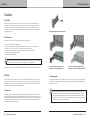 10
10
-
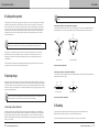 11
11
-
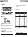 12
12
-
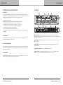 13
13
-
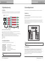 14
14
-
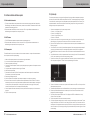 15
15
-
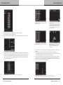 16
16
-
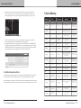 17
17
-
 18
18
-
 19
19
-
 20
20
-
 21
21
-
 22
22


