
size:420x180mm
FIBER OPTIC VIEWING SCOPE KIT
OPERATION INSTRUCTIONS
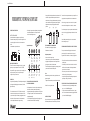
BATTERY REPLACEMENT
Use two AA batteries to properly power your fiber scope
•Remove the battery housing cover near the viewing end of the
scope body, sliding it to the direction of the arrow as show
below.
•Insert batteries and put back the cover.
IMPORTANT INFORMATION:
ST and SC connector ferrule lengths vary slightly. If you have
aligned your scope to accept the SC connector, DO NOT
fully seat the ST version for inspection. If you have aligned your
scope to accept the ST version, it may be necessary to
re-align it to accept SC connectors.
OPERATION
Using the 200X adjustable scope: The 200X adjustabl magnifier
is configured with a field aligning aluminum head. (See Field
Alignment Section)
•To view the ferrule end of an ST or SC fiber connector, slide
the ferrule into the inspection port until it bottoms-out. On SC
type connectors, it may be necessary to apply pressure to the
back strain relief boot to ensure the ferrule end meets the
minimum depth-of-field needed for proper viewing.
• Viewing the image can be accomplished by focusing with the
thumb-wheel adjustment knob. You may first want to
switch on the internal light source.
Inspection Examples:
RELACING THE BULB OR ADDING OTHER
SCOPE HEAD ASSEMBLIES
• Hold scope base unit in one hand with your thumb resting on
the bulb side of the clear plastic lens.(see drawing )
• Apply thumb pressure against the plastic lens to the right side
until it pops loose (about 1/4 inch of lateral movement can be
expected)see drawing.
• Lift off the plastic lens by applying a two finger prying motion
on the broad sides of the lenssee see drawing3.
• Unscrew old bulb and replace with a new incandescent 2.25V,
0.25 AMP or like part (available at your local hardware or
electronics store). If changing the head assembly, simply snap
on the new head and re-align the plate by loosening the two
alignment screws and positioning the place with thumb
pressure.
FIELD ALIGNMENT OF ALUMINUM HEAD
Tools needed to perform aligning adjustment:
• Small electronics screwdriver.
Adjustment procedure:
• Insert connector in inspection port.
• Loosen screws on top of the aluminum plate head piece.
• Align image and hold plate and clear lens together while
tightening one of the two hold-down screws.
• Perform find adjustment by viewing image and placing thumb
pressure on the side of the aluminum plate.
Note:
Be aware that image will move in the opposite direction that
pressure is applied.
• Tighten the last screw when you are satisfied with the view.
Caution: Do not over-tighten screws.
CARE AND STORAGE
Store your fiber inspection scope in appropriate temperatures.
Extreme temperatures can shorten the life of your instrument.
Dust and dirt can cause premature wear on your scope. Be sure
to gently clean the scope with a lint free cloth after each use.
When not using your scope, be sure to store it in a protected
case to avoid lens damage from sun, dust, dirt, or moisture.
Do not clean any portion of your scope with a harsh chemical or
solvent. Use a dry (or) slightly dampened with alcohol, lint free
cloth.
Caution: Always remove all epoxy from connector ferrules
before inserting into scope.
REPAIRING AND RESTORATION OF A REJECTED FINISH
For any connector face exhibiting signs of dust, bacterial
growth, epoxy, fluid, or contamination, use only an optic
approved lint free cloth and 90% (or better) isopropyl alcohol.
• Place the lint free cloth on a cushioned consistent surface i.e.
a polishing pad.
• Add a few drops of alcohol to one side of the cloth and buff
the fiber end on the saturated cloth using moderate hand
pressure for about 15 seconds.
• Move to a dry section of the lint free cloth and once again buff
the fiber end using firm hand pressure.
• Inspect finish using the 200X scope with angle adapter and
repeat steps 1 through 3 if necessary.
FOR SCRATCHED OR SLIGHTLY BLEMISHED SURFACES
• For distinct scratches or very slight core/cladding fractures
use 1.0 to 1.5um DIAMOND lapping film.
• For light scratches, surface blemishes, undercut, or epoxy
fold-over, first use standard acetate 1um lapping film followed
by 0.5 micron DIAMOND lapping film.
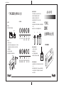
ldeal
Coarse
surface
Rework
again
Dirty or
residual
clean up
or rework
Heavy
damaged
Throw
away
Broken
Throw
away
Defect
Throw
away
Light
scratches
Polish
more on
3um film
Heavy
scratches
Rework
again
Edge
damaged
Rework
again
Broken
Throw
away
open
Right push
pull up
fig.1 fig.2 fig.3

size:420x180mm
200X
200X
(AA)
• 200
1. SC ST
2.
3.
1.
2.
3.
4.
2.25V/0.25AMP
5.
6.
1. -
2.
3.
4.
1.
2. 1.0-1.5um
1um
0.5um
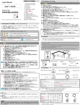
8PK-MA009
1
6
0
x
2
0
0
x
open
-
 1
1
-
 2
2


他の言語で
- English: Pro'sKit 8PK-MA009 Owner's manual

その他のドキュメント
-
 Z-Works DN3G6JA062 ユーザーマニュアル
-
Equip 255329-V1 データシート
-
Hikoki DV18DL2 ユーザーマニュアル
-
Hikoki DV 14DL ユーザーマニュアル
-
Hitachi DS 10DAL Handling Instructions Manual
-
Hitachi DB3DL2 Handling Instructions Manual
-
-
Hikoki ds 9dvf3 ユーザーマニュアル
-
Hikoki DV 14DBL ユーザーマニュアル
-
Leica V-Lux 5 クイックスタートガイド
