
zh
安装说明
en Installationinstructions
9000 948 050 (9311)
KF..W..

zh
索引
安装
. . . . . . . . . . . . . . . . . . . . . . . . . . . . 4
安装电器
. . . . . . . . . . . . . . . . . . . . . . . . . 4
电气连接
. . . . . . . . . . . . . . . . . . . . . . . . . 5
安装尺寸
. . . . . . . . . . . . . . . . . . . . . . . . . 5
en Index
Installation . . . . . . . . . . . . . . . . . . . . . . . . . 6
Installing the appliance
................6
Electrical connection
.................. 7
Installation dimensions
................ 7


4
zh
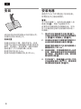
安装
请在阅读安装说明前取出中间的图示页,
以便结合图示阅读正文。
安装位置
电器应安装在干燥、通风的室内。安装
位置不应有阳光直射或靠近热源
(
例如电
暖炉、炊具等
)
。如有需要,请使用隔热
板或遵守下列与热源的最小距离:
距离用电的灶具
3 cm
。
距离用油或固体燃料的灶具
30 cm
。
安装电器
请使用
Torx T 20
螺丝起子安装电器。
所需固定件已随电器提供。
重要!
为了保护玻璃门,请先将本电器置入安
装橱
(
图
%
)
,再拆下运输保护件。
若要将本电器贴紧房间隔断安装,则在
位于电器安装区域的安装橱后部加装一
块隔板。
1.
用水平仪仔细地调平立橱
(
图
!
/1)
。
立橱必须用螺丝牢牢固定在相邻橱柜
上
(
图
!
/2)
或墙体上
(
图
!
/3)
。
2.
本电器必须通过立橱底板位置的开口
以及后部的风道进行通风
(
图
"
)
。
底板位置的通风开口以及风道的最小
横截面积为
200 cm
2
。
3.
安装电源线,并用细绳将其拉入合适
位置,确保电器安装完毕后电源线能
接入插座。将电器推入立橱。请勿缠
绕电源线
(
图
#
)
。
4.
打开电器门,将嵌条插入外壳上方的
片状金属支架中
(
图
$
/1)
。然后用附
带的螺丝固定嵌条
(
图
$
/2)
。

5
zh
5.
拆除运输保护件:
拧下螺纹固定部件
(
图
%
/1)
。
拆下用粘合剂固定的运输保护件
(
图
%
/2)
。托住塑料部分,请勿按
压。用手抓住凸片,沿着平行于底板
的方向慢而直地拉出条状材料。
将附带的罩盖安装到外壳上
(
图
%
/3)
。
安装磁铁
(
图
%
/4)
。
6.
将附带的安装橱固定件
(
图
&
/1)
插
入外壳。
将异型条
(
图
&
/2)
调整到与立橱内
部等高的位置,并将其粘至电器门打
开侧的外壳上。
如果立橱的侧面板厚度为
16 mm
(
或更薄
)
,则应取出附带的垫片
(
图
&
/3)
,并将其插入铰链臂。
7.
将电器推入立橱,直至顶部的止动
条
(
图
'
/l)
和门铰链上方的止动件
(
'
/2)
位于立橱的前沿位置。然后将
电器装有铰链的一侧向右移,直到达
到立橱的侧面板位置。
8.
用螺丝将电器分别固定至立橱的侧
面
(
图
(
/1)
、顶部
(
图
(
/2)
和底部
(
图
(
/3)
。
插入罩盖
(
图
(
/4)
。
9.
松开螺钉
(
图
)
/1)
,调整电器门。
重新拧紧螺钉。将罩盖
(
图
)
/2)
推
到铰链上。
10.
安装门把手
(
图
)
/3)
。
为防止损坏,门把手作为电器的随机
附件分开存放。
电气连接
电源插座应处在方便操作的位置,以立
橱上方为佳。在安装完成前不要运行本
电器。
将电器推入立橱时,注意不要挤压电
源线。
通过规范的安装连接到
220–240 V/
50 Hz
的交流电源上。
插座必须装有
10 A
以上的保险丝。如
果在
非欧洲国家
使用电器,请检查铭牌
上所指示的电源电压、电流类型以及频
率是否符合您所使用的电源。铭牌位于
电器内部的左下侧。
电源线只能由电工更换。
安装尺寸
图
*

6
Installation
Please detach the illustrated centre
pages before reading the installation
instructions. You can now read the text
in conjunction with the illustrations.
Installation location
Install the appliance in a dry, well
ventilated room. The appliance should
not be installed in direct sunlight or near
a heat source (e.g. radiator, cooker).
If required, use an insulating plate
or observe the following minimum
distances from the heat source.
3 cm to an electric cooker.
from an oil or solid-fuel cooker 30 cm.
Installing the appliance
A Torx T 20 screwdriver is required for
installation.
The required fixtures are enclosed with
the appliance.
Important!
To protect the glass door, do not remove
the transportation protection devices
until the appliance has been placed in
the cavity, Fig.
%
.
If installing the appliance in a room
divider, line the rear of the installation
cavity in the area of the appliance.
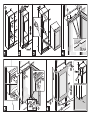
1. Carefully align the high-sided unit
with a spirit level, Fig.
!
/1. The
high-sided unit must be screwed
securely to the adjacent units, Fig.
!
/2, or to the wall, Fig.
!
/3.
2. The appliance must be ventilated
by an opening in the base and a
duct at the rear of the high-sided
unit Fig.
"
.
Minimum cross-section of the
ventilation openings in the base
and duct: 200 cm
2
.
3. Install the power cord and pull into
the required position with a piece
of string, ensuring that the socket
is accessible after the appliance
has been installed. Slide appliance
into the high-sided unit. Do not
trap the power cord Fig.
#
.
4. When the door is open, insert the
cover strip into the sheet-metal
brackets on the housing, Fig.
$
/1.
Screw on the cover strip with the
enclosed screws, Fig.
$
/2.
en

7
5. Remove the transportation
protection devices:
Unscrew the screwed-on parts,
Fig.
%
/1.
Remove the glued-on
transportation protection devices,
Fig.
%
/2. Hold the plastic part, do
not press on it. Take hold of the
tab and slowly pull out the strip
straight and parallel to the base.
Fit enclosed cover to the housing,
Fig.
%
/3.
Attach magnet, Fig.
%
/4.
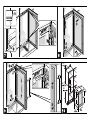
6. Insert the enclosed cavity fixture,
Fig.
&
/1 into the housing.
Adjust the profiled strip, Fig.
&
/2,
to the inside height of the high-
sided unit and glue to the housing
on the door opening side.
If the side panels of the high-
sided unit are 16 mm (or thinner),
separate the enclosed spacers,
Fig.
&
/3, and insert into the hinge
arms.
7. Push the appliance into the high-
sided unit until the stop bar at the
top, Fig.
'
/l, and the stops on the
door hinges, Fig.
'
/2, are situated
on the front edge of the high-
sided unit. Move the hinge side of
the appliance right up to the side
panel of the high-sided unit.
8. Screw the appliance to the side,
Fig.
(
/1, to the top, Fig.
(
/2, and
to the bottom, Fig.
(
/3, of the
high-sided unit.
Insert the caps, Fig.
(
/4.
9. Loosen the screws, Fig.
)
/1, and
align the door. Retighten the
screws. Push the caps, Fig.
)
/2,
onto the hinges.
10. Attach the door handle, Fig.
)
/3
To prevent damage, the door
handle is enclosed loosely with
the appliance.
Electrical connection
The socket should be freely accessible,
preferably above the high-sided unit.
Do not operate the appliance until it has
been installed.
When sliding the appliance into the
high-sided unit, do not pinch the power
cord.
Connect the appliance to 220-240 V/
50 Hz alternating current via a correctly
installed earthed socket.
The socket must be fused with a 10 A
fuse or higher. If the appliance is to be
operated in a non-European country,
check on the rating plate whether
the indicated supply voltage, current
type and frequency of the appliance
correspond with the specifications of
your power supply. The rating plate is
situated in the bottom left-hand side of
the appliance.
The power cord may be replaced by an
electrician only.
Installation dimensions
Fig.
*
en

4

最小
最小
最小

*9000592511*
9000 948 050 (9311)
-
 1
1
-
 2
2
-
 3
3
-
 4
4
-
 5
5
-
 6
6
-
 7
7
-
 8
8
-
 9
9
-
 10
10


Siemens KF18WA43/03 ユーザーマニュアル
- タイプ
- ユーザーマニュアル
- このマニュアルも適しています
他の言語で
- English: Siemens KF18WA43/03 User manual
