Yealink Yealink VC500 Full HD Video Conferencing Endpoint (CN,EN) V43.10 クイックスタートガイド
- タイプ
- クイックスタートガイド

Yealink VC500 Full HD Video Conferencing Endpoint Quick Start Guide
V43.10
Yealink Network Technology CO., LTD
English | 简体中文
Applies to firmware version 63.43.0.10 or later

VCH50 Video
Conferencing Hub
3m
Ethernet Cable
AAA Batteries×2
1.2m
Mini-DP Cable
0.5 m
Ethernet Cable
1.2m
HDMI Cable
(for content sharing)
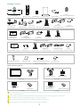
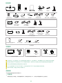
Package Contents
VC500 Codec
VCR11
Remote Control
OK
1
Acrylic board
VC500
Quick Start Guide
2
2
2
Cable Tie×5
Power Adapter
VESA Accessory
Mounting Bracket
and Accessories
Velcro×2
(One Velcro is on the bracket)
1.8m
HDMI Cable
(for thedisplay device)
1
7.5m
Ethernet Cable
USB Dongle
B Package
DD10
CPW90 Wireless
Mic×2
Bluetooth Wireless
Microphones×2
Bluetooth USB Dongle
BT42
C Package
We recommend that you use the accessories provided or approved by Yealink. The use of unapproved third-party accessories may
result in reduced performance.
VC500 endpoint canwork with VCH50/VCH51 Wired Sharing package or Wireless Sharing package for sharing content.
VC500 endpoint can work with A package, B package, C package or D package.
Use the power adapter provided by Yealink to charge the wireless microphones only.
Put the magnet rings on the HDMI cable to prevent electromagnetic interference.
CTP20
VCM34
WPP20
Quick Start Guide
WPP20 Wireless Presentation Pod
Wireless Sharing Package
Wi-Fi USB Dongle WF50 WF50 User Guide
Optional Accessories
A Package
Camera Lens
Privacy cover
D Package
CP960
Conference Phone
CPE90 Wired
Expansion Mic×2
VCH51 Wired Sharing Package
Interface
Protective Cover
7.5m
Ethernet Cable
0.6m
USB Type-C Cable
(for content sharing)
VCH51
Quick Start Guide
0.6m
HDMI Cable
(for content sharing)
VCH51
Video Conferencing Hub
VCH50 Wired Sharing Package

Endpoint Installation
2
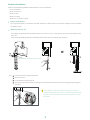
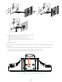
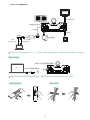
Mount on top of a TV
Select one of the following installation method based on your site requirements:
Put on a Flat Surface
Mount on top of a TV
Mount on a wall
Mount on a ceiling
Mount onto a TV stand or a tripod
.
.
.
.
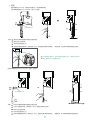
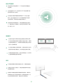
Put on a Flat Surface
You can put the endpoint on a conference room table, and make sure that the slope is not more than 5 degrees so that the endpoint
can operate correctly.
.
Steps:
1
3
2
4
3
TV
4
3
Push the bracket to an appropriate location.
Remove one Velcro.
Put the bracket on the top of the TV.
Stick a Velcro onto the back of the TV, and make sure that the bracket and the back of the TV are tightly positioned against
each other.
Pay attention to the direction of the bracket
2
1
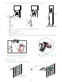
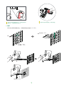
If your endpoint cannot be mounted on the top of a TV when the
bracket has reached the given location, you should remove the bracket,
and then convert its direction. Refer to the following section for more
information.
The endpoint may fall down when the thickness of the TV is more than 77 mm. In this situation, do not mount the endpoint on the
top of a TV.
Please choose the following installation method when the thickness of the TV is between 1mm and 36mm.

Do not pick up the bracket which connects with
an endpoint, the endpoint may fall down
in this situation.
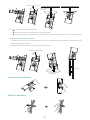
Mount on a Wall
The recommended height is 1.55m-1.85m above the ground.
Steps:
1
3
2
4
3
Push the bracket along the track of the endpoint to an appropriate location.
Stick a Velcro onto the bracket.
Remove one Velcro.
Put the bracket on the top of the TV.
Stick a Velcro onto the back of the TV, and make sure that the bracket and the back of the TV are tightly positioned against
each other.
5
3
Please choose the following installation method when the thickness of the TV is between 37mm and 77mm.
TV
Pay attention to the direction of the bracket
4
5
3
1
2
X
If your endpoint cannot be mounted on the top of a
TV when the bracket has reached the edge of the
endpoint, choose other installation methods.
48mm
Hole diameter: 6mm
Hole depth: 30mm
Screw specification: T4×30
2
1
300mm

4
Steps:
1
2
3
4
Punch holes into the wall and then insert the expansion bolts.
Secure the bracket using the T4×30 screws.
Push the endpoint along the track of the bracket.
Secure the endpoint onto the bracket using the M3×8 screws.
Screw specification: M3×8
Reset
Reset
Reset
3
4
Mount on a Ceiling
.
.
.
45.97mm
1.81in
14.0mm
0.55in
Screw hole
6.0 mm(0.24 in.) in depth
Location hole
5.0 mm(0.20 in.) in diameter
If you choose the ceiling-mounted installation, you need to purchase a bracket separately. The bracket must meet the following
requirements:
Able to bear the weight of at least 10.5kg (23.15 lb.) and the thickness must be between 2mm (0.08 in.) and 3 mm (0.12 in.).
Comes with a location pillar, which can be inserted into the location hole of the VESA accessory.
The distance between the screw on the bracket and the location pillar must be 14 mm (0.55 in.).

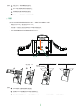
Mount onto a TV Stand or a Tripod
Steps:
1
2
3
5
Remote Control Installation
Push the VESA accessory along the track.
Secure the VESA accessory to the endpoint using the M3×8 screws.
Align the location pillar at the location hole, and then secure the bracket to the VESA accessory using the 1/4”-20 UNC screw.
SN
MAC
Reset
SN
MAC
Reset
SN
MAC
Reset
Screw specification: M3×8
1
2
3
SN
MAC
Reset
Screw specification:
1/4”-20 UNC
SN
MAC
Reset
SN
MAC
Reset
SN
MAC
Reset
Screw specification: M3×8
SN
MAC
Reset
1
2
3
TV Stand
You need to purchase a TV stand or a tripod separately. The TV stand or tripod has the same requirements as the bracket used in the
ceiling-mounted installation method.
The installation steps are the same as the ceiling-mounted installation steps.
Screw specification:
1/4”-20 UNC
Cable Ties Installation

6
VCH50
MINI DP HDMI
Codec
Audio
Power Adapter
VC Hub/Phone
HDMI 2
SN
MAC
Internet
HDMI 1
DC48V
Reset
Display×2
1.8m
HDMI Cable
7.5m
Ethernet Cable
3m
Ethernet Cable
Connections
VCM34
PoE
CTP20
7.5m
Ethernet Cable
3m
Ethernet Cable
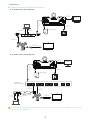
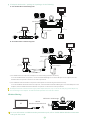
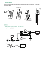
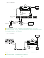
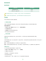
If you do not need the VCH50/VCH51 video conferencing hub to share content, you can connect the VC Hub/Phone port on the system
to the PoE port on the VCM34 directly.
If endpoint works with A package, do the following:
A: For VCH50 video conferencing hub:
B: For VCH51 video conferencing hub:
Power Adapter
VC Hub/Phone
HDMI 2
SN
MAC
Internet
HDMI 1
DC48V
Reset
Display×2
1.8m
HDMI Cable
7.5m
Ethernet Cable
3m
Ethernet Cable
...
IEEE 802.3af
compliant PoE Switch
HDMI
PC
0.6m
HDMI Cable
0.6m USB
Type-C Cable
or
PC
VCH51
PoE
VCM34
PoE
CTP20
7.5m
Ethernet Cable
7.5m
Ethernet Cable
3m
Ethernet Cable
PC
1.2m
Mini-DP Cable or
1.2m
HDMI Cable

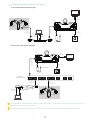
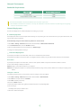
If endpoint works with B package, do the following:
CP960
VC Hub/Phone
HDMI 2
SN
MAC
Internet
HDMI 1
DC48V
Reset
VCH50
MINI DP HDMI
Codec
Audio
If you do not need the VCH50/VCH51 video conferencing hub to share content, you can connect the VC Hub/Phone port on the system to the
PoE port on the CP960 conference phone directly.
When CP960 conference phone is connected to the endpoint, the 3.5mm audio output port and the Micro USB port are not available.
Display×2
1.8m
HDMI Cable
3m
Ethernet Cable
7.5m
Ethernet Cable
Power Adapter
0.5m
Ethernet Cable
CPE90 Wired
Expansion
CPE90 Wired
Expansion
A: For VCH50 video conferencing hub:
B: For VCH51 video conferencing hub:
PC
1.2m
Mini-DP Cable or
1.2m
HDMI Cable
CP960
0.5m
Ethernet Cable
CPE90 Wired
Expansion
CPE90 Wired
Expansion
Power Adapter
VC Hub/Phone
HDMI 2
SN
MAC
Internet
HDMI 1
DC48V
Reset
Display×2
1.8m
HDMI Cable
7.5m
Ethernet Cable
3m
Ethernet Cable
...
IEEE 802.3af
compliant PoE Switch
HDMI
PC
0.6m
HDMI Cable
0.6m USB
Type-C Cable
or
PC
VCH51
PoE
7.5m
Ethernet Cable
7

8
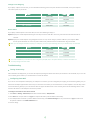
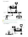
For more information on WPP20 wireless presentation pod, refer to Yealink WPP20 Wireless Presentation
Pod Quick Start Guide.
Wireless Sharing
WPP20
Wireless Presentation Pod
PC
VC Hub/Phone
HDMI 2
SN
MAC
Internet
HDMI 1
DC48V
Reset
WF50 Wi-Fi USB Dongle
If endpoint works with C package or D package, do the following:
Power Adapter
VC Hub/Phone
HDMI 2
SN
MAC
Internet
HDMI 1
DC48V
Reset
Display×2
1.8m
HDMI Cable
3m
Ethernet Cable
USB Dongle
a) The CPW90 wireless microphones and endpoint are automatically paired from the factory.
To use the CPW90 wireless microphones, connect the DD10 USB dongle to one of the USB ports on the endpoint, then the
CPW90 wireless microphones can work as the audio input devices.
b) The CPW90-BT bluetooth wireless microphones and endpoint are automatically paired from the factory.
To use the CPW90-BT bluetooth wireless microphones, connect the BT42 bluetooth USB dongle to one of the USB ports on the
endpoint, then the CPW90-BT bluetooth wireless microphones can work as the audio input devices.
The endpoint should be used with Yealink original power adapter (48V/0.7A) only. The use of the third-party power adapter may
cause the damage to the endpoint. The cable should be replaced at once if its skin is broken.
MINI DP HDMI
Codec
Audio
7.5m
Ethernet Cable
PC
1.2m
Mini-DP Cable or
1.2m
HDMI Cable
A: For VCH50 video conferencing hub:
B: For VCH51 video conferencing hub:
Power Adapter
VC Hub/Phone
HDMI 2
SN
MAC
Internet
HDMI 1
DC48V
Reset
Display×2
1.8m
HDMI Cable
3m
Ethernet Cable
USB Dongle
HDMI
PC
0.6m
HDMI Cable
0.6m USB
Type-C Cable
or
PC
VCH51
PoE
7.5m
Ethernet Cable

9
Network Environment
Bandwidth Requirements
Both downlink bandwidth and uplink bandwidth should meet above requirements.
The bandwidth mentioned above is based on a two-way call. Bandwidth in head office should be increased along with the growing
number of connected branch offices.
Network Deployment
Choose Cloud deployment or traditional deployment according to your need.
Cloud Deployment
Cloud deployment does not need complex network settings. You only need to get account information from your system administrator, and
log into video conference platform.
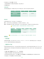
Do the following to log into video conference platform via remote control:
1. Select More->Setting->Advanced (Default Admin Password:0000)->Video Conference Platform.
2. In the Cloud Account field, check the Enabled checkbox.
3. Select the desired platform from the pull-down list of Platform Type.
4. Configure the desired platform and log in.
Video Resolution Recommended Bandwidth
Full HD 1080P 1.3Mb
People 1080P+Content 1080P 2.6Mb
Traditional Deployment
If you deploy the endpoint in the head office, make sure it is reachable from public network.
If you deploy the endpoint in the branch office, use intelligent traversal to deploy it or just follow the same steps as for the head office.
Head Office
If you deploy the endpoint in the head office, at least one static public IP address is required to allow branch offices to connect.
Do one of the following to deploy the endpoint:
Option1: Assign a static public IP address to your endpoint.
Option2: If you deploy the endpoint in an Intranet (behind the firewall), assign a static private IP address to it and do port mapping on the
firewall.
Configure a Static IP
The following introduces how to use the remote control to configure a static IPv4 address:
1. Select More->Setting->Advanced (Default Admin Password:0000)->Wired Network.
2. Select IPv4 from the pull-down list of IP Mode.
3. Select IPv4, and then press OK key.
4. Uncheck the DHCP checkbox.
5. Enter the IP address, subnet mask, gateway and DNS information in corresponding fields.
6. Save the change.
The display device prompts “Reboot now?”
.
7. Select
OK
to reboot the
endpoint.

Configure Port Mapping
If you deploy endpoint in an Intranet, you must forward the following ports to the public network on the firewall, so that your endpoint
can receive a public-to-private call.
Branch Office
If you deploy VC500 endpoint in the branch office, do one of the following to deploy it:
Option1: Deploy the VC500 endpoint following the same steps as for the head office. In this way, both inbound and outbound calls are
available.
Option2: Deploy the VC500 endpoint using intelligent traversal. You only need to assign a private IP address to your endpoint. Make
sure this private IP address can access the public network. Only outbound calls are available when using this method.
When you use intelligent traversal to deploy your endpoint, you have to open following ports on your firewall if they are restricted.
It is recommended that you forward the web management port(443/TCP) to the public network, so that the head office can
remotely manage the branch office.
PortFunction
H.323 signal port
SIP optional
Audio & Video media stream port
Web management port optional
Protocol Type
UDP/TCP
5060-5061
443
50000-51000
1719-1720
TCP/UDP
TCP/UDP
TCP
PortFunction
H.323 signal port
SIP optional
Audio & Video media stream port
Protocol Type
UDP/TCP
TCP/UDP
TCP/UDP
50000-51000
5060-5061
1719-1720
Troubleshooting
Testing Connectivity
After installation and deployment, you can test the endpoint by dialing the Yealink Demo Room (117.28.251.50 or 117.28.234.45). If you can’t dial
out successfully, please contact your IT administrator to check the network.
Configuring Static NAT
If you do not use Cloud platform and deploy your endpoint in an Intranet, you have configured port mapping on the firewall or gateway, but you
find that local endpoint appears black screen and you cannot hear sound when you call Yealink Demo or other endpoints. The most likely reason
is that the firewall or gateway in your environment does not support the ALG feature. In this situation, please take the following actions so that
the static NAT feature on the endpoint can solve this problem.
To configure static NAT via the remote control:
1. Select More->Setting->Advanced (Default Admin Password:0000)->NAT/Firewall.
2. Select Auto from the pull-down list of Type, the endpoint will obtain public IP address automatically.
3. If the endpoint does not obtain a public IP address automatically, select Manual Settings from the pull-down list of Type, and then enter
the public IP address in the Public IP Address field.
4. Save the change.
10

包装清单
将终端摆放在水平桌面。如果桌面略有倾斜,请保证倾斜角小于5°,以保证终端的摄像机云台正常运转。
平放安装
你可以根据实际需要选择安装终端的方式:
OK
2
2
2
1
VCR11遥控器
VCH50接线盒
7号电池x2
VC500主机
亚克力牌
电源适配器
1.8米HDMI线
(用于接显示设备)
1.2米Mini-DP线
(用于分享辅流)
7.5米网线
VESA配件
支架配件
(用于安装主机)
魔术贴x2
(一套已贴在支架上)
VC500
快速入门指南
会议电话套件
CP960会议电话
CPE90有线扩展麦x2
1.2米HDMI线
(用于分享辅流)
束线带x 5
0.5米网线
3米网线
蓝牙无线麦×2
USB蓝牙设备
BT42
CPW90-BT蓝牙无线麦克风套件
此为A级产品。在生活环境中,该产品可能会造成无线电干扰。在这种情况下,可能需要用户对干扰采取切实可行的措施。
我们推荐使用由Yealink提供或经Yealink认可的配件和线缆,使用未经认可的第三方配件和线缆可能会导致性能的下降。
你可以选择有线辅流或无线辅流套件进行内容共享。
VC500主机可搭配CTP20与VCM34套件,会议电话套件或CPW90-BT蓝牙无线麦克风套件使用。
使用HDMI线前,请套上磁环用于抗电磁干扰。
安装终端
VC500
最佳部署实践方案
VCH50有线辅流套件
WPP20 无线传屏助手
USB无线网络适配器WF50
WF50用户指南
WPP20快速入门指南
无线辅流套件
可选配件
镜头隐私盖
11
接口保护罩
VCH51
快速入门指南
0.6米USB Type-C线
(用于分享辅流)
VCH51有线辅流套件
7.5米网线
VCH51接线盒
0.6米HDMI线
(用于分享辅流)
CTP20
VCM34
CTP20与VCM34套件

步骤:
1
3
2
4
3
将支架沿着终端底部轨道推至合适的位置。
撕开支架上的魔术贴。
将支架挂在电视的上方。
在电视背部黏贴魔术贴(魔术贴为一次性,黏贴前注意清洁电视背后),调整支架,使支架和电视的背面完全紧贴。
当电视厚度范围为37mm-77mm时,进行以下步骤:
步骤:
1
3
2
4
3
将支架沿着终端底部轨道推至合适的位置。
在支架上黏贴魔术贴(魔术贴为一次性,黏贴前注意清洁支架)。
撕开支架上的魔术贴。
将支架挂在电视的上方。
在电视背部黏贴魔术贴(魔术贴为一次性,粘贴前注意清洁电视背后),调整支架,使支架和电视的背面完全紧贴。
5
1
2
3
4
5
注意支架的方向
当支架接触到限位点,还不能放置在电视顶上时,请取出支架反向
装配。请参阅下文了解更多信息。
电视
限位点
12
挂装
4
3
1
2
电视
注意支架的方向
电视厚度超过77mm时,请勿使用挂装方式,机器有跌落风险。
当电视厚度范围为1mm-36mm时,进行以下步骤:

请勿手持支架拿起机器,有掉落风险。
当支架与底壳边缘位置齐平,还不能放置在电
视顶上时,请使用其他安装方式。
X
48mm
墙装
你可以用支架将终端安装在墙上,终端安装高度建议范围为1.55-1.85m。
打孔直径: 6mm
打孔深度: 30mm
螺丝规格:T4x30
螺丝规格:M3x8
Reset
Reset
Reset
3
4
2
1
13
300mm

1
3
2
4
3
在墙上打孔,将膨胀螺栓固定至墙上。
用T4×30型号的螺丝将支架固定到墙上。
将终端底部沿着支架的轨道往里推。
用两个M3×8型号螺丝将终端锁在支架上。
步骤:
1
3
2
3
将VESA配件沿着终端底部轨道往里推。
使用两个M3×8型号螺丝将VESA配件锁到终端上。
将支架自带的定位柱对准VESA配件的定位孔,并将1/4”-20UNC英制螺钉旋进VESA配件的螺丝孔。
步骤:
SN
MAC
Reset
3
螺丝规格:M3x8
SN
MAC
Reset
1
2
SN
MAC
Reset
SN
MAC
Reset
45.97mm14.0mm
螺丝孔
深度:6.0mm
定位孔
直径:5.0mm
螺丝规格:
1/4-20UNC英制螺钉
吊装
用户可以自行选购支架来将终端倒挂在天花板上,选购的支架必须满足以下条件:
承重至少为10.5kg,厚度建议为2mm-3mm。
支架配套一个定位柱,定位柱用来插入VESA配件的定位孔中。
支架上的英制螺钉和定位柱的直线距离必须为14mm。
.
.
.
14

螺丝规格:M3x8
SN
MAC
Reset
SN
MAC
Reset
SN
MAC
Reset
2
电视架
3
SN
MAC
Reset
电视架或三脚架安装
用户可以自行选购电视架或三脚架来固定终端,电视架或三脚架的选购要求与使用吊装方式时的支架要求相同。电视架或三脚架
安装步骤与吊装步骤相同。
1
2
3
螺丝规格:
1/4-20UNC英制螺钉
连接终端
如果终端搭配CTP20与VCM34套件,请按下图完成连接:
15
VCH50
MINI DP HDMI
Codec
Audio
VC Hub/Phone
HDMI 2
SN
MAC
Internet
HDMI 1
DC48V
Reset
VCM34
PoE
CTP20
PC
A: 对于VCH50有线辅流分享:
显示设备x2
1.8米HDMI线
3米网线
3米网线
7.5米网线
7.5米网线
1.2米Mini-DP线
1.2米HDMI线
或
电源适配器

CP960
VC Hub/Phone
HDMI 2
SN
MAC
Internet
HDMI 1
DC48V
Reset
显示设备x2
1.8米HDMI线
0.5米网线
7.5米网线
有线扩展麦
有线扩展麦
VCH50
MINI DP HDMI
Codec
Audio
CP960会议电话与终端相连时,3.5mm音频输出接口和Micro USB接口不可用。
如果你无需使用VCH50/VCH51进行演示,可以使用7.5米网线将CP960会议电话的Internet接口直接连在终端的VC Hub/Phone
接口上。
如果终端搭配会议电话套件,请按下图完成连接:
VC Hub/Phone
HDMI 2
SN
MAC
Internet
HDMI 1
DC48V
Reset
B: 对于VCH51有线辅流分享:
显示设备x2
1.8米HDMI线
3米网线
3米网线
7.5米网线
7.5米网线
电源适配器
...
HDMI
PC
PC
VCH51
PoE
VCM34
PoE
CTP20
IEEE 802.3af 标准
PoE交换机
7.5米网线
0.6米
USB Type-C线 或 0.6米HDMI线
A: 对于VCH50有线辅流分享:
如果你无需使用VCH50/VCH51进行演示,可以使用网线将VCM34的PoE接口直接连在终端的VC Hub/Phone接口上。
我们要求使用Yealink原装电源(48V/0.7A),使用第三方电源可能会导致终端损坏。如果使用过程中发现线缆破皮,请立即更换。
3米网线
电源适配器
16

如果终端搭配CPW90-BT蓝牙无线麦克风套件,请按下图完成连接:
VC Hub/Phone
HDMI 2
SN
MAC
Internet
HDMI 1
DC48V
Reset
显示设备x2
1.8米HDMI线
电源适配器
3米网线
USB蓝牙设备BT42
CPW90-BT
17
A: 对于VCH50有线辅流分享:
VCH50
MINI DP HDMI
Codec
Audio
PC
7.5米网线
1.2米Mini-DP线
1.2米HDMI线
或
CP960
VC Hub/Phone
HDMI 2
SN
MAC
Internet
HDMI 1
DC48V
Reset
显示设备x2
1.8米HDMI线
0.5米网线
7.5米网线
有线扩展麦
有线扩展麦
CP960会议电话与终端相连时,3.5mm音频输出接口和Micro USB接口不可用。
如果你无需使用VCH50/VCH51进行演示,可以使用7.5米网线将CP960会议电话的Internet接口直接连在终端的VC Hub/Phone
接口上。
B: 对于VCH51有线辅流分享:
...
3米网线
电源适配器
7.5米网线
HDMI
PC
PC
VCH51
IEEE 802.3af 标准
PoE交换机
0.6米
USB Type-C线 或 0.6米HDMI线
PoE

我们要求使用Yealink原装电源(48V/0.7A),使用第三方电源可能会导致终端损坏。如果使用过程中发现线缆破皮,请立即更换。
安装遥控器电池 使用束线带
18
B: 对于VCH51有线辅流分享:
VC Hub/Phone
HDMI 2
SN
MAC
Internet
HDMI 1
DC48V
Reset
显示设备x2
1.8米HDMI线
电源适配器
3米网线
USB蓝牙设备BT42
CPW90-BT
7.5米网线
HDMI
PC
PC
VCH51
PoE
0.6米
USB Type-C线 或 0.6米HDMI线
WPP20无线传屏助手
想要了解WPP20无线传屏助手的详细信息,请参阅亿联WPP20无线传屏助手快速入门指南。
连接无线辅流
PC
VC Hub/Phone
HDMI 2
SN
MAC
Internet
HDMI 1
DC48V
Reset
WF50 USB无线网络适配器

视频会议室的部署可分为如下几个模块:光线、摄像机放置、拾音/声音播放、画面显示、接线。以下是针对这些模块的具体建议,在会
议室装修与视频会议设备部署的过程中可参考以下内容取得更佳的视频会议效果。
视频会议室部署
45
。
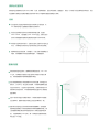
光线
会议室的灯光应更多地聚焦在会议桌与参会人的位置,以
45° 斜照向参会人面部是较为理想的光照条件。
如会议室原有的光线不足可考虑加装平面光源,色温以
4000~5000k,光照强度以300~500lux为宜。光线充足与
否可以视频画面中面部肤色是否真实还原作为评判标准。
即使会议室采光条件良好,也建议在会议过程中打开会议室
灯光,以确保会议桌与参会人区域有充足且均匀的光照度。
摄像机避免正对强光源,例如窗户。以免出现人物图像逆光
现象。如果摄像机不可避免地朝向窗口,可装配窗帘。
摄像机放置
根据实际的会议室情况,摄像机安装高度建议在 1.55~1.85
m之间。如果是较大型的会议室/会场则不受限于此建议高
度,可根据被摄物体距离确定摄像机高度。
建议将摄像机放置于电视顶部水平居中的位置。如果显示设
备较大(大于80寸)或应用了拼接屏,可考虑将摄像机固定
在显示设备下方,但应高于会议桌高度。为提升视频会议中
的眼神交流与互动感,尽可能将摄像机靠近显示对方视频画
面的屏幕。
投影+电视作为显示设备的情况下,将电视架推车尽可能靠
近投影幕布,摄像机放置于电视上靠近投影幕布的一侧。
面积较大的会议室/会场可考虑吊顶倒装摄像机,但需避免
摄像机直接安装于天花板推荐使用吊架降低摄像机高度。需
注意摄像机高度/角度调节范围相对第一排参会者距离的关
系。以摄像机离地 2.5m为例,第一排参会者与摄像机的距
离应至少 2m为宜。
1.55 (m)
1.85 (m)
19
ページが読み込まれています...
ページが読み込まれています...
ページが読み込まれています...
ページが読み込まれています...
-
 1
1
-
 2
2
-
 3
3
-
 4
4
-
 5
5
-
 6
6
-
 7
7
-
 8
8
-
 9
9
-
 10
10
-
 11
11
-
 12
12
-
 13
13
-
 14
14
-
 15
15
-
 16
16
-
 17
17
-
 18
18
-
 19
19
-
 20
20
-
 21
21
-
 22
22
-
 23
23
-
 24
24


Yealink Yealink VC500 Full HD Video Conferencing Endpoint (CN,EN) V43.10 クイックスタートガイド
- タイプ
- クイックスタートガイド
他の言語で
関連論文
-
Yealink Yealink VC200 Video Conferencing Endpoint (CN,EN) V43.10 クイックスタートガイド
-
-
-
-
-
Yealink WPP20 クイックスタートガイド
-
-
Yealink MeetingBar A20 Microsoft Team Video Bar ユーザーガイド
-
-
Yealink WF50 ユーザーマニュアル

