Therabody B09479WNLM ユーザーガイド

タイプ
ユーザーガイド
1
EN 2-14
TW 15-27
CN 28-40
KR 41-53
JP 54-66
Table of Contents
2
EN
RecoveryAir PRO
Your RecoveryAir PRO pneumatic compression system comes with a pump, a pair of compression
boots, a blocker plug, a DC power adapter, and a carrying pouch for both the pump and boots.
Fully customizable pneumatic compression system.
See Warnings on pg. 8 for important safety instructions.
1. To turn on the RecoveryAir PRO pump, press and hold the power button.
2. To get started, put your boots on first before attaching them to the pump. This allows you to get
into the most comfortable position and avoid any disruption in the air flow connection.
3. Next, plug in the connector from the boots into the pump. Make sure you hear a “click” so that
you know the RecoveryAir PRO is fully connected, is plugged in, and there is a proper seal.
4. Once connected and comfortable, you are ready to customize your treatment.
1. To turn on the RecoveryAir PRO pump, press and hold the power button.
2. Customize your treatment from the pump interface.
3. Using the left & right arrows in the 4-way button, scroll through the 5 preset treatment options:
Recover, Warm-up, Isolation, Interval, and PRO Mode (Custom).
4. Once you have chosen your desired treatment preset, use the up & down arrows in the 4-way
button to adjust the pressure setting.
5. To create a custom routine, simply press the select button until a new screen appears.
6. Then, use your select and arrow buttons to navigate the options such as Pressure, Time, Hold,
Release, and Gradient, creating a fully personalized routine.
7. Once you have selected the treatment options that are right for you, push play, relax,
and you’ll be on your way to recovery in no time. You can also share your routines with
other RecoveryAir users easily through the Therabody app.
Getting started
Customizing your treatment
EN
3
Indicators
Buttons
Start/Pause/Stop Button
Select Button
Warning Indicator
Indicator lights up solid ON or blinking when
a device malfunction is detected
Bluetooth Indicator
Indicator turns ON only when connected
to the App
Battery Indicator
3 LED lights to indicate battery life
Power Button
Feature Callouts
4-way Buttons
Time Setting
10min-90min.
Pressure Setting
Adjustable Pressure Range (20-100 mmHg)
in increments of 5 mmHg. Adjustable
Pressure Range in increments of 1mmHg
(Gradient Setting).
Settings (Adjustable Range)
4
EN
RecoveryAir PRO Programs
About negative gradient for all programs:
The RecoveryAir PRO’s unique true negative gradient of pressure sequentially travels up
the limb from the foot toward the heart in four internal overlapping chambers. The spiraling
overlap of chambers safely maximizes circulation.
The pressure can be the same in two consecutive chambers, but the pump won’t allow
a back chamber to have a higher pressure than a front chamber.
The minimum pressure level of each chamber is 20 mmHg.
Recover and Warm-Up preset programs
The Recover program is the perfect go-to when experiencing fatigue, tension, or
soreness brought on by your everyday activities or post workout.
The Warm-Up program is recommended for use before a workout.
The only difference between the two programs is the default pressure level and
treatment time.
Sequential inflation cycle
Both the Recovery and Warm-Up preset programs use the Sequential inflation cycle.
A directional massage is applied, starting at the base of the treated area, and progresses
upwards towards the torso and then releases. (see Figure 1)
Starting with Chamber 1, once the inflating chamber has reached its preset pressure
level, the pressure level for that chamber is held and the next chamber begins inflating.
Chamber 4
Chamber 3
Chamber 2
Chamber 1
Figure 1 - Sequential Cycle Mode
Isolation preset program
The Isolation program is recommended when needing to treat a specific, isolated area
of your choosing.
Isolation inflation cycle (ISO)
The Isolation program provides targeted compression to a selected zone.
A directional massage is applied to a smaller, isolated area.
Inflation starts with the front chamber.
The next chamber starts to inflate after a few seconds.
Until both chambers reach the set pressure and deflate at the same time, the cycle
will start again after a short pause (see Figure 2).
Isolated Areas:
Full Distal Zone – Chamber 1, 2, & 3
Distal Zone – Chamber 1 & 2
Mid Zone – Chamber 2 & 3
Proximal Zone – Chamber 3 & 4
Full Proximal Zone – Chamber 2,3, & 4
Distal Mid Proximal
Figure 2 - ISO Cycle Mode
EN
5
PRO Mode (Custom)
The PRO Mode allows you to create a fully customized program that’s unique to you.
You can use the Pretreatment program or you can choose from four inflation cycles:
Sequential, Isolation, Wave, or Flow.
During your treatment, you can change the treatment parameters, but you can’t change
the selected inflation cycle and can’t turn the pre-selected program ON/OFF.
Pretreatment (See Figure 3)
Pretreatment treats the proximal areas first.
A specific pattern is applied, and the duration varies according to garment size (5–12
minutes) with a preselected pressure of 30 mmHg in all chambers that cannot be changed.
Sequence 1 is carried out six times.
Sequence 2 and Sequence 3 are carried out only once.
Sequential inflation cycle (see page 4)
Isolation inflation cycle (see page 4)
Wave inflation cycle
The Wave inflation cycle starts at the base of the limb, over the foot.
As one chamber inflates, the previous chamber starts deflating, so at any one time a small
area is being compressed.
For example: When chamber 2 is full, then chamber 1 starts to deflate, while chamber 3
starts to inflate, so for a moment, there are 2 chambers reaching the target pressure at the
same time. (See Figure 4)
Interval preset program
The Interval program allows for a cycle to turn on and then off in a sequential selected amount
of time.
A directional massage is applied with a sequential cycle, and alternates between intervals
of being under treatment (Time On) and no treatment (Time Off).
Start by selecting the Time On (in minutes), the Time Off (in minutes), and the total Interval
program time (in hours).
The treatment begins with the selected Time On, and after this treatment is completed, the
pump pauses for the selected amount of Time Off, and then back to the selected Time On.
This Time On/Time Off interval continues automatically until the total treatment time is
completed (up to 8 hours).
Total Time
Time On Time Off Time On
Sequential CycleTreatment
Sequential Cycle
Treatment
No Treatment . . .
Time On Time O Total (hrs)
10 — 90 min
(5min per step)
10 — 90 min
(5min per step)
1 — 8 hours
(1hr per step)
Figure 1 - Sequential Cycle Mode
Sequence 1 Sequence 2 Sequence 3
Figure 4 - Wave Cycle Mode
Figure 3 - Pretreatment Sequences
RecoveryAir PRO Programs
Chamber 4
Chamber 3
Chamber 2
Chamber 1
6
EN
PRO Mode (Custom)
Flow inflation cycle
Four sequences exist within the Flow inflation cycle. Each sequence is determined by the last chamber inflated.
The Flow inflation cycle has an associated Frequency parameter, which determines the number of sequences within the cycle.
You can set the Frequency to be between 1 and 8.
The default Frequency setting is 2.
Examples
Frequency 1 - Each chamber inflation sequence happens once before continuing to next chamber sequence.
Frequency 2 - Each chamber inflation sequence repeats twice before continuing to next chamber sequence .
Frequency 8 - Each chamber inflation sequence repeats eight times before moving to the next chamber inflation.
Chamber 1 Chamber 2 Chamber 3 Chamber 4
Progress
Sequence Sequence
Progress
Sequence Sequence
Progress
Sequence Sequence
Progress
SequenceSequence
Smart Features
The RecoveryAir PRO also connects to the Therabody app via Bluetooth, giving you total
control of your RecoveryAir PRO session from the convenience of your smartphone.
Not only can you easily access options like individual chamber pressure, but you can
create and share custom routines with your friends, clients, or patients directly from
the app via text message or email. Scan the QR code
to get started.
EN
7
Charging the RecoveryAir PRO
Lock & unlock feature:
Factory reset
1. After turning off the pump, plug the power adapter into the charging port of the RecoveryAir PRO pump.
2. You can continue to use the RecoveryAir PRO while charging.
3. Charging is complete when all 3 LED lights of the LED battery indicator are lit.
1. To lock or unlock the pump, press and hold the select and up arrow at the same time.
2. You will then see a padlock icon appear on the main screen.
You can perform a factory reset to change all customized programs back to the original default setting by
following this easy step:
1. Press and hold the select and play/stop buttons.
Superior, hygienic design
The RecoveryAir PRO compression boots have non-porous medical grade material that helps prevent bacteria buildup and provides a resistant surface. Our internal
overlapping chambers provide a smooth surface to clean, which means no wiping under chamber flaps where bacteria can build up. This also means no smells.
How to Clean
Here are simple steps to cleaning your RecoveryAir PRO compression boots:
1. Unzip the boots completely and lay them on a flat surface.
2. Take a disinfectant wipe or spray, and gently clean the inside of the boots. Avoid any oil based cleaning product.
3. Once you have cleaned your garment, make sure to fully dry the surface by hanging them up or wiping them down.
4. We also recommend you wipe down the exterior of the pump to reduce surface contaminants.
What it is and why it’s important:
We use medical-grade material covering the internal chamber to help reduce the potential for microbial growth and moisture retention. Whether you are an
individual, or a clinic, our boots are designed to help limit the potential for bacterial transmission.
Traveling with your RecoveryAir PRO Compression System
When traveling with your RecoveryAir PRO Compression System, we recommend:
●Roll the hose tightly and slide it into the foot section of your garment. It is important to keep the hose from creasing to protect the hose’s integrity and its ability to
properly distribute airflow.
Once you secure the hose, simply fold your garment to fit into your travel bag or carry-on luggage.
Secure your pump in the provided carrying pouch.
Select Button Start/Pause/
Stop Button
8
EN
Important Safety Information
Read all instructions before using the RecoveryAir PRO Compression System for the first time.
Warning
This system is intended for use by people in good health. This system is not recommended for people who have heart problems, or vascular problems, have a condition requiring the use of any medical
device, or have any condition that may affect their normal well-being.
If you are, or may be, pregnant, consult with your physician before use.
Do not use this system over insensitive or numb areas, or in the presence of poor circulation. Do not use if you have been diagnosed with blood clots, deep vein thrombosis or phlebitis. This system
should not be used over swollen or inflamed areas or skin eruptions. Do not use in the presence of unexplained calf pain.
Consult your physician prior to use.
Safety Warnings and Precautions
Warning:
Explosion Hazard: Do not use the RecoveryAir PRO Compression System in the presence of flammable gases, including flammable anesthetics.
Electric Shock Hazard: Do not allow liquid to enter any part of the RecoveryAir PRO Compression System pump. Do not immerse in water or liquid. To clean, follow instructions found on page 7.
Electric Shock Hazard: To prevent electric shock, do not open the pump. Do not attempt to service the pump yourself. All repairs should be performed only by Therabody trained and authorized service
personnel. Service by unauthorized personnel will void any warranty.
Stop using the system if there is any change in RecoveryAir PRO Compression System’s performance.
Do not modify any part of the RecoveryAir PRO Compression System.
The RecoveryAir pneumatic compression system includes small parts that could cause choking in children. Keep away from children and pets.
Do not inflate the garment without wearing it over the intended body area or with open zippers. Doing so can damage the garment.
Do not apply excessive force to the garment straps. Do not use the straps for any purpose other than intended by the manufacturer. Use of excessive force and/or misuse shall void the manufacturer’s
warranty.
Do not stand or walk while wearing the garment.
Disconnect the pump from the electrical outlet before cleaning and let it dry completely before reconnecting it to the electrical outlet.
Caution
Do not operate the RecoveryAir PRO Compression System while operating a vehicle.
Do not store or transport the RecoveryAir PRO Compression System beyond the specified temperature, humidity, and atmospheric pressure range.
Do not use the RecoveryAir PRO Compression System beyond the specified temperature range: 10 to 30°C (50 to 86°F).
Do not use the RecoveryAir PRO Compression System beyond the specified humidity range: 30%rH–75%rH,
non-condensing.
Only use the RecoveryAir PRO Compression System up to 3000m above mean sea level.
To prevent any damage to the RecoveryAir PRO Compression System, keep it away from dust, lint, and dirt. Keep away from sources of heat or moisture.
●To prevent any damage to equipment, use only accessories, detachable parts, and materials described in this
User Manual.
While in use, place the pump on a horizontal firm surface only. Do not place the pump on a bed, blanket, mattress, pillow, or soft furniture. Do not cover the pump.
The equipment is to be installed and put into service according to the EMC information provided in Chapter 11 - EMC Manufacturer Declarations.
Portable and mobile RF communication equipment might affect the equipment.
For indoor use only.
Use only the DC power adapter provided with the pump.
The massage sensation should be pleasant and comfortable. If you experience pain or discomfort during or after the massage or if there is onset of bruising or irritation during or after the
massage, discontinue use and consult your physician.
Do not hand or machine wash. Surface wipe only.
Do not allow liquid to get into the air inlets.
Do not use bleach.
Do not dry clean.
Do not wring, iron, tumble, or force heat dry.
EN
9
Labels
The following labels and symbols appear on the pump, garments and/or packaging.
Label Description Location
IP 22 Degree of protection against ingress of water On console base
Read instructions before use On console base
Read instructions before use (for China only) On console base
Read instructions before use On garment label
Level of protection type BF applied part On garment label
Class III equipment
Equipment relying on limitation of voltage to
extra-low-voltage (ELV) values as provision for
basic protection and with no provision for fault
protection.
On console base
Therabody, Inc.
6100 Wilshire Blvd. Suite 200 Los Angeles,
CA 90048
On garment label
and console base
UDI :
(01) 00810036057400
(10)
(21)
2143
00001
Unique Device Identication (UDI)
On garment label
and package, and
garment bag and
package
Label Description Location
Separate collection for waste electrical and
electronic equipment
Note: For more information about disposal of
equipment, its parts and accessories, please
contact your local distributor.
On console base
In accordance with Directive 2014/35/EU
electrical equipment designed for use within
certain voltage limits, and Directive 2014/30/EU
electromagnetic compatibility
On console
Serial number of the console On console base
Do not wash On garment tag
Do not dry-clean On garment tag
Do not tumble dry On garment tag
Do not bleach On garment tag
Do not iron On garment tag
10
EN
Indications for Use
RecoveryAir is indicated for the temporary relief of minor muscle aches and pains, and for the temporary increase in circulation to the treated areas in people who are in good health. RecoveryAir
simulates kneading and stroking of tissues by using an inflatable garment.
Note
The pump is “multi-voltage” and can be used for travel.
An appropriate socket adapter must be used in countries with incompatible wall outlets.
Use only RecoveryAir garments with the RecoveryAir pump.
When immediate garment deflation is necessary, disconnect the garment hose bundle from the pump to immediately deflate the air pressure in the garment.
Troubleshooting
Symptom Possible Cause Corrective Action
The pump is not working. No electricity Inspect the electrical wall outlet.
DC power adapter Verify that the DC power adapter cable is connected to the DC adapter
socket on the console, and the DC power adapter is connected to the 100-
240 Volt wall outlet.
DC power adapter cable Examine the cable for any defects.
The Status Indicator is On in yellow Malfunction Contact Therabody.
The pump starts working and stops immediately. The air cannot move through the garment hose. Examine hoses for kinks, twists and folds.
One garment inflates but the second one does not. The second garment does not receive air. Examine its hoses for kinks, twists and folds.
The pump stops working, the Status Indicator turns
On in yellow.
Hose is not connected properly to garment or pump,
or prong plug is not inserted into unused air outlet.
Examine and fasten all air connections. When treating only one limb, always
plug the unused air outlet with the prong plug provided with the pump. If all
air connections are OK and the problem persists, contact Therabody.
The pump works at a very low
pressure, regardless of the pressure set by the user.
Defective garment Replace garment and check again.
Internal malfunction Contact Therabody.
An irregular noise. Pump transferring vibrations to a surface Make sure the pump is standing evenly on all four of its bumpers.
Internal malfunction Contact Therabody.
Warranty
For full warranty information, please visit www.therabody.com/warranty. To request a copy of the warranty by mail, you may send a request to the following address:
Therabody - WarrantyAttn: Customer Service, 6100 Wilshire Blvd., Los Angeles, CA 90048
Please note, this is not a return address or a retail location. No products or packages will be accepted at this location.
EN
11
Bluetooth Wireless Technology Information
Electromagnetic Compatibility (EMC)
Statement for Home Healthcare Environment
The RecoveryAir PRO system has been evaluated to international standard IEC 60601- 1-2
“General requirements for basic safety and essential performance - Collateral standard:
Electromagnetic compatibility - Requirements and tests”.
The Medical Electrical Equipment needs special precautions regarding EMC and needs to
be installed and put into service according to the EMC information provided here within the
accompanying documents.
Portable and mobile RF communication can affect the Medical Electrical Equipment. See below
recommended separation distances between portable and mobile RF communication equipment
and the RecoveryAir PRO system.
Wireless communications equipment such as wireless home network devices, mobile phones,
cordless telephones and their base stations, walkie-talkies can affect this equipment and should
be kept at least a distance d = 3.3 m away from the system. *Note: The distance calculated from 800 MHz to 2.5 GHz
Bluetooth Compliance Version 4.2 low energy
Operating Frequency 2.402–2.480 GHz
Output Power 0 dBm
Operating Range 3-meter radius (line of sight)
Network Topology Star - bus
Operation Slave
Antenna Type Integrated chip type antenna
Modulation Type Adaptive Frequency Hopping
Data Rate Over the air: 1 Mbit/second
Application throughput: 0.27 Mbit/s
Data Latency 6 ms
Data Integrity Adaptive Frequency Hopping
Robustness 24-bit CRC (cyclic redundancy check)
32-bit message integrity check
Quality of Service This device uses Bluetooth smart technology for
wireless communication, which allows for reliable
communication in electrically noisy environments.
If connection is lost, the device will automatically
reconnect in a few seconds.
Bluetooth Profiles Supported GAP, GATT, SM, L2CAP and Integrated Public
Profiles
Authentication and Encryption Supported
EMC Manufacturer Declarations Rated Maximum
Output Power of
Transmitter (W)
Separation Distance*
according to Frequency
of Transmitter (m)
0.01 0.23
0.1 0.73
1 2.3
10 7.3
100 23
12
EN
Frequency Identification (RFID), etc. or MR environment. EMI, RF devices or MR environments may affect the normal function of the device or would cause user injury.
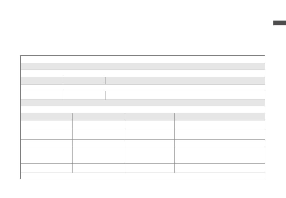
Guidance and Manufacturer’s Declaration – Electromagnetic Emission
The RecoveryAir PRO device is intended for use in the electromagnetic environment specified below. The customer or the user of the device should assure that it is used in such an environment .
Emission Test Compliance Electromagnetic Environment – Guidance
The device uses RF energy only for its internal function. Therefore, its RF emissions are very low and are not likely to cause any interference in nearby electronic equipment.
IEC 61000-3-3 Class B The device is suitable for use in all establishments, including domestic establishments and those directly connected to the
public low-voltage power supply network that supplies buildings used for domestic purposes.
Caution: Basic Safety and Essential Performance
This system should not be used adjacent to or stacked with other equipment and that if adjacent or stacked use is
necessary, this system should be observed to verify normal operation in the configuration in which it will be used.
The essential performance of the RecoveryAir PRO system as evaluated in IEC 60601- 1-2 includes treatment completing cycle, presentation on the display is not interfered, and treatment parameters
are not changed unintentionally.
The following, but not limited to, are unacceptable risks that are not allowed: malfunction, non-operation when operation is required, unwanted operation when no operation is required, deviation from
normal operation that poses unacceptable risk to operator or user, component failure, change in programmable parameter(s), change in operation mode, reset to factory defaults, and false positive or
false negative alarm.
Do not apply the device near any devices with Electromagnetic Interference (EMI), such as cell phones, Magnetic Resonance Imaging (MRI), computerized axial tomography (CT), diathermy, Radio
Guidance and Manufacturer’s Declaration – Electromagnetic Immunity
The RecoveryAir PRO device is intended for use in the electromagnetic environment specified below. The customer or the user of the device should assure that it is used in such an environment.
Immunity Test IEC 60601 Test Level Compliance Level Electromagnetic Environment - Guidance
Electrostatic discharge (ESD) IEC
61000-4-2
2, 4, 6, 8 kV contact
2, 4, 8, 15 kV air
2, 4, 6, 8 kV contact
2, 4, 8, 15 kV air
Floors should be wood, concrete or ceramic tile. If floors are covered
with synthetic material, the relative humidity should be at least 30%
Electrical fast transient/burst
IEC 61000-4-4
±2 kV for power supply lines
±1 kV for input/output lines
±2 kV for
power supply lines
Mains power quality should be that of a typical commercial or hospital
environment.
Surge
IEC 61000-4-5
±1 kV line(s) to line(s)
±2 kV line(s) to earth
±1 kV line(s) to line(s)
±2 kV line(s) to earth
Mains power quality should be that of a typical commercial or hospital
environment.
Voltage dips, short interruptions and
voltage variations on power supply
input lines
IEC 61000-4- 11
<5% UT(>95% dip in Ut) for 0.5 cycles
40% Ut (60% dip in Ut) for 5 cycles
70% Ut (30% dip in Ut) for 25 cycles
<5% Ut (>95% dip in Ut) for 5 sec
<5% UT(>95% dip in Ut) for 0.5 cycles
40% Ut (60% dip in Ut) for 5 cycles
70% Ut (30% dip in Ut) for 25 cycles
<5% Ut (>95% dip in Ut) for 5 sec
Mains power quality should be that of a typical commercial or hospital
environment. If the user of the device requires continued operation
during power mains interruptions, it is recommended that the device
be powered from an uninterruptible power supply or a battery
Power frequency (50Hz/60Hz)
magnetic field IEC 61000-4-8
30 A/m 30 A/m Power frequency magnetic fields should be at levels characteristic of a
typical location in a typical commercial or hospital environment.
Note: UT is the AC mains voltage prior to application of the test level.
EN
13
Guidance and Manufacturer’s Declaration – Electromagnetic Immunity
The RecoveryAir PRO device is intended for use in the electromagnetic environment specified below. The customer or the user of the device should assure that it is used in such an environment.
Immunity Test IEC 60601 Test Level Compliance Level Electromagnetic Environment - Guidance
Conducted
Immunity
61000-4-6
3 Vrms/m
for
0.15MHz to 80MHz
6 Vrms/m
for ISM & amateur
radio band.
3 Vrms/m
for
0.15MHz to 80MHz
6 Vrms/m for
ISM & amateur
radio band.
Portable and mobile RF communication equipment should be used no closer to any part of the device,
including cables, than the recommended separation distance calculated from the equation applicable to the
frequency of the transmitter.
Recommended separation distance
= 1 . 2
= 1 . 2 80 MHz to 800MHz
= 2 . 3 800 MHz to 2.7 GHz
Where P is the maximum output power rating of the transmitter in Watts (W) according to the transmitter
manufacturer and d is the recommended separation distance in meters (m). Field strengths from fixed RF
transmitters, as determined by an electromagnetic site survey(a) should be less than the compliance level in each
frequency range(b) . Interference may occur in the vicinity of equipment marked with the following symbol:
Radiated
Immunity
61000-4-3
10 V/m
80MHz to 2.7GHz
10 V/m
Note 1: At 80 MHz and 800 MHz, the higher frequency range applies.
Note 2: These guidelines may not apply in all situations. Electromagnetic propagation is affected by absorption and reflection from structures, objects and people.
(a). Field strengths from fixed transmitters, such as base stations for radio (cellular/cordless) telephones and land mobile radios, amateur radio, AM and FM radio broadcast and TV broadcast
cannot be predicted theoretically with accuracy. To assess the electromagnetic environment due to fixed RF transmitters, an electromagnetic site survey should be considered. If the measured
field strength in the location in which the device is used exceeds the applicable RF compliance level above, the device should be observed to verify normal operation. If abnormal performance is
observed, additional measures may be necessary, such as re-orienting or relocating the device. (b). Over the frequency range 150 kHz to 80 MHz, field strengths should be less than 3 V/m.
Recommended Separation Distances between Portable and Mobile RF Communication Equipment and the Device
The RecoveryAir PRO device is intended for use in an electromagnetic environment in which radiated RF disturbances are controlled. The customer or the user of the device can help prevent
electromagnetic interference by maintaining a minimum distance between portable and mobile RF communication equipment (transmitters) and the device as recommended below, according
to the maximum output power of the communications equipment.
Rated Maximum Output
Power of Transmitter (W)
Separation Distance
According to Frequency of Transmitter (m)
150 kHz to 80 MHz 80 MHz to 800 MHz 800 MHz to 2.7 GHz
0.01 0.12 0.12 0.23
0.1 0.38 0.38 0.73
11.2 1.2 2.3
10 3.8 3.8 7.3
100 12 12 23
For transmitters rated at a maximum output power not listed above, the recommended separation distance in meters (m) can be estimated using the equation applicable to the frequency of the
transmitter, where P is the maximum output power rating of the transmitter in Watt (W) according to the transmitter manufacturer.
Note 1: At 80 MHz and 800 MHz, the separation distance for the higher frequency range applies.
Note 2: These guidelines may not apply in all situations. Electromagnetic propagation is affected by absorption and reflection from structures, objects and people.
14
EN
Storage environment:
The pump can be transported or stored for short periods of time within:
Temperature range of -4 - 158°F (-20- 70°C)
Humidity range of 10-93% RH non-condensing
Atmospheric pressure range of 190 - 1060hPa
Allow the pump to reach a reasonable room temperature of 50 - 86°F (10 - 30°C) before operating.
When the system has been stored in extreme temperature conditions of -20°C (-4°F) or 70°C (158°F) between uses, wait for two (2) hours before using again.
Radiation Exposure statement
This equipment complies with FCC/IC RSS-102 radiation exposure limits set forth for an uncontrolled environment.
15
TW RecoveryAir PRO
󲹢󵒹󴉶󱕜󱼻󶌯󶂻󶆢󸿢󳥥󰵨󱂑󲩳󴑚󽴷󰵨󹃲󱼻󶌯󵴴󹈴󽴷󰵨󱂑󳏅󹍨󱹇󽴷󰵨󱂑󹄷󴙃󸍳󳍻
󱬽󰻄󱛼󰵨󱂑󵈾󳜵󲩳󴑚󱠥󵴴󹈴󵒹󹂒󸉩󳙑󶃞󷟎󽴸
󵖬󱜴󶩉󷪏󵒹󴉶󱕜󱼻󶌯󶂻󶆢󽴸
󷰟󱛯󸼘󵳨󹌥󵒹󷵫󱟈󽴺󰸬󷩒󸡿󷦵󵒹󲔟󽤤󲶎󷯟󳟉󽴸
 󷦵󸻛󱥭󲩳󴑚󽴺󷰟󳉿󰽟󹄷󴙃󳉿󸤉󽴸
 󷦵󸻛󲄦󰾫󵈾󽴺󷰟󱋔󵭮󰵴󵴴󹈴󽴺󴬮󲲖󲘠󲔑󱂜󸔯󳍻󱑍󲩳󴑚󽴸󸔐󱜴󰻄󷷋󲹢󳆫󱑍󳥔󶪟󸗡󵒹󰽚󶔩󽴺󰶜󰶃󸘛󱋞󰻥󰽧󴉶
󴐪󸔯󳍻󵒹󰶦󳜭󽴸
 󳍻󰵵󰾶󽴺󲘠󹈴󲒪󵒹󸔯󳍻󱬽󳏅󱌆󲩳󴑚󰶦󽴸󷰟󵠸󱁄󶝄󱑍󱦝󱮈󶜬󽴺󲁫󷷋󲹢󵛽󸖦󲦻󲔥󽤤󸔯󳍻󽴷
󳏅󱌆󰶜󰶃󳥥󶽾󸗡󵊺󵒹󲖚󲘔󽴸
 󰵨󳞊󸔯󳍻󰶜󳆫󱑍󶪟󸗡󵒹󰽚󶔩󽴺󱙱󱜴󶩉󷪏󲹢󵒹󴍜󵐿󽴸
 󷦵󸻛󱥭󲩳󴑚󽴺󷰟󳉿󰽟󹄷󴙃󳉿󸤉󽴸
 󲲱󲩳󴑚󵉳󹈘󶩉󷪏󴍜󵐿󽴸
 󰾫󵈾󱝣󳉿󸤉󰶦󵒹󲦪󱜹󵷬󹍨󽴺󱙸󱕜󴣴󷨓󱂑󹌹󷫥󴍜󵐿󸘈󹌫󼶊󽴷󽴷󽴷󰻄
󱛼󼵸󶩉󷪏󼵹󽴸
 󰵨󳞊󸘈󳕶󰸬󳄿󹄿󵒹󴍜󵐿󹌹󷫥󽴺󷰟󰾫󵈾󱝣󳉿󸤉󰶦󵒹󱝣󰵴󱠥󱝣󰵵󵷬󹍨󰾶󷰆󳚯󳉿󱼻󱼻󱔃󷫥󲕂󽴸
 󷦵󲮋󵰩󶩉󲕂󳍗󵪒󽴺󱜬󹄿󳉿󸘈󳕶󳉿󸤉󵕭󱑍󱐁󵀎󳜟󵊦󹈘󽴸
 󳍻󶽾󽴺󰾫󵈾󸘈󳕶󱠥󵷬󹍨󳉿󸤉󰾶󴣴󷨓󸘈󹌫󽴺󰿀󲁷󽴷󽴷󽴷󱠥󽴺󲮋󵰩󲔥󽤤󶩉
󷪏󵒹󳍗󵪒󽴸
 󰵨󳞊󸘈󳕶󰸬󸗡󱝗󵒹󴍜󵐿󸘈󹌫󽴺󳉿󰵵󳕆󳙟󽴺󳙟󸌌󹡽󽴺󲹢󲘠󲲏󲴱󲙡󳥛󲷬󲳃󴸝󲾁󽴸󲹢󰷴󱜴󰻄󸔓󸖖
󳁱󵈾󵪒󲮮󸌌󹡽󱲓󶪆󱌧󰺯󰾫󵈾󶙐󱐖󰹨󲹢󵒹󳍗󵪒󽴸
󸻛󲄦󰾫󵈾
󶩉󷪏󲹢󵒹󴍜󵐿
16
TW
󳉹󵤛󴱛
󳉿󸤉
󼵸󸻛󲄦󼵹󼵿󼵸󳢿󱄣󼵹󼵿
󼵸󱄣󴃻󼵹󳉿󸤉
󸘈󳕶󳉿󸤉
󷵫󱟈󳉹󵤛󴱛
󳾟󴖡󱑍󷫥󱆕󳙧󹁼󳠙󳉹󵤛󴱛󳥛󲨣󰹯󳃵󸻑󴳫
󷋞󴶇󳉹󵤛󴱛
󳉹󵤛󴱛󱇧󳥛󱲉󸔯󶊂󱑍󳁱󵈾󵪒󲮮󳠙󰹯󸁲
󹄷󴋓󳉹󵤛󴱛
󰻄󱂑󽤤󰹯󵒹󴱛󳯮󰾶󳉹󵤛󹄷󴋓󱽾󱠑
󼵸󹄷󴙃󸮴󼵹
󱔇󶡌󴶷󲶎󳺧󷫾
󱝣󳉿󸤉󰶦
Time
󱐖󸳼
Pressure
󱜴󷰆󳚯󵒹󱼻󱔃󵸖󱱡󼵸󼵹󰻄
󸗄󱻟
󱜴󷰆󳚯󵒹󱼻󱔃󵸖󱱡󰻄󸗄󱻟
(Gradient Setting).
󷫥󲕂󼵸󱜴󷰆󳚯󵒹󵸖󱱡󼵹
17
TW
Isolation 預設療程
󵊺󹄿󷦵󴍜󵐿󲹢󸘈󳕶󵒹󴶷󲕂󹁭󹄇󱘧󱶗󳠙󽴺󲮋󷵿󰾫󵈾󵐿󵪒󽴸
Isolation 充氣循環 (ISO)
󵐿󵪒󴩁󸘈󲕂󱘧󱶗󳏀󰿙󳥥󸢛󲘪󲶎󵒹󱼻󶌯󽴸
󲕂󱝣󳉿󳓓󸗡󵈾󳜵󸋲󲘮󵒹󽴷󹁭󹄇󵒹󱘧󱶗󽴸
󳥛󲲱󱑺󹈘󵒹󱔉󱼻󶭆󸻛󲄦󱋐󴉶󽴸
󳚹󵨳󸳼󲲖󽴺󰵵󰵨󱂑󱔉󱼻󶭆󳥛󸻛󲄦󱋐󴉶󽴸
󵕭󱑍󱌎󱂑󱔉󱼻󶭆󸛫󸖩󱑍󷫥󲕂󵒹󳉿󱼻󱼻󱔃󰶜󳥛󱝛󳠙󳙟󴉶󽴺󵜋󳢿󵒹󳢿󱄣󲲖󽴺󲳆󵅈󲘠󳥛󱍅󴂅
󸻛󲄦󼵸󷧆󱱭󼵹󽴸
隔離區域
󳦤󵱯󱘧󱶗󱔉󱼻󶭆󱠥
󲔥󳚯󳦤󵱯󱘧󱶗󱔉󱼻󶭆󽴷󱠥
󰶦󴆰󱘧󱶗󱔉󱼻󶭆󱠥
󵐿󵪒
關於所有療程的副梯度
󵒹󴼭󴶷󵖬󷼿󱼻󳰒󲫟󽴺󱲉󱰌󱂑󱌼󸛉󸡿󵋖󱔉󱼻󶭆󰶦󰿝󲪹󲲱󸃉󸛉󲲄󰵴󱝣󲳲󶨶󳜱󱝣󵩶󱕜󽴸
󱔉󱼻󶭆󵒹󷙡󳝓󸡿󵋖󶡌󲔟󽤤󱲓󳥔󱿑󱗌󲳆󵅈󽴸
󱌎󱂑󸔯󶏶󱔉󱼻󶭆󰶦󵒹󱼻󱔃󱜴󰻄󵕲󱝛󽴺󰽏󲩳󴑚󰵷󱋉󷫫󲲖󶭆󵒹󱼻󱔃󹠟󳜵󱑺󶭆󽴸
󱝑󱂑󱔉󱼻󶭆󵒹󳥔󰽝󱼻󱔃󵴟󶃺󴩁󽴸
Recover 和 Warm-Up 預設療程
󵐿󵪒󳟾󱲉󳞉󲨣󴐟󱕜󳃵󱄵󸉩󲲖󲼯󱑍󵌖󱕫󽴷󶉞󲯺󳃵󵍵󵍦󳠙󵒹󲔥󶕢󸘈󳕶󽴸
󲮋󷵿󱲉󱄵󸉩󱑺󰾫󵈾󵐿󵪒󽴸
󱌎󱂑󵐿󵪒󸻧󵒹󱤕󰵨󱘧󱐾󳟾󹌹󷫥󵒹󱼻󱔃󵴟󶃺󱠥󴍜󵐿󳠙󸻧󽴸
依序充氣循環
󱠥󹌹󷫥󵐿󵪒󸛫󰾫󵈾󱋐󴉶󲳆󵅈󽴸
󸕏󷝥󲕂󱝣󳉿󳓓󽴺󲲱󴍜󵐿󱘧󱶗󵒹󲫂󸛉󸻛󲄦󽴺󰶜󲲄󰵴󳦋󶽾󸊓󲪎󳜱󱝣󸕏󷝥󽴺
󳍻󶽾󸡽󳙟󱼻󱔃󼵸󷧆󱱭󼵹󽴸
󲲱󱔉󱼻󶭆󸻛󲄦󽴺󰵨󳞊󱔉󱼻󶭆󸖩󱑍󱌧󹌹󷫥󱼻󱔃󵴟󶃺󽴺󱔉󱼻󶭆󵒹󱼻󱔃󵴟󶃺󲘠󳥛󶈟󳉱󰵷󷶷󽴺
󰶜󰶃󰵵󰵨󱂑󱔉󱼻󶭆󱑲󸻛󲄦󱋐󴉶󽴸
󱔉󱼻󶭆
󱔉󱼻󶭆
󱔉󱼻󶭆
󱔉󱼻󶭆
圖 1 – Sequential 循環模式
󸗈󵱯 󰶦󴆰 󸑝󵱯
圖 2 – ISO 循環模式
󸑝󵱯󱘧󱶗󱔉󱼻󶭆󱠥
󲔥󳚯󸑝󵱯󱘧󱶗󱔉󱼻󶭆󽴷󱠥
18
TW
󱔉󱼻󶭆
󱔉󱼻󶭆
󱔉󱼻󶭆
󱔉󱼻󶭆 󼵸󶩉󷪏󼵹
󱋉󷫫󲮋󵰩󲔥󽤤󶩉󷪏󵒹󵐿󵪒󽴺󸔐󳟾󲹢󲘡󲛃󵒹󵐿󵪒󽴸
󲹢󱜴󰻄󰾫󵈾󹌹󱋔󴍜󵐿󵐿󵪒󽴺󳃵󶙐󱜴󰻄󲲱󱰌󱂑󱋐󴉶󸕌󳦎󰶦󸘈
󳕶󼶊󽴷󽴷󽴺󳃵󶙐󽴸
󱲉󴍜󵐿󳦎󸻧󽴺󲹢󱜴󰻄󷶷󳥀󴍜󵐿󱛯󳚹󽴺󰽏󰵷󶡌󷶷󳥀󸘈󳕶󵒹󱋐󴉶󸕌󳦎󽴺󰷴󰵷󶡌󸻛󱥭󼵿󸽡󸻘󹌹󱋔
󸘈󳕶󵒹󵐿󵪒󽴸
預先治療 (見圖 3)
󹌹󱋔󴍜󵐿󳥛󱋔󴍜󵐿󸑝󵱯󱘧󱶗󽴸
󲘠󳥛󳁱󵈾󴶷󲕂󳺹󲮮󽴺󰶜󰶃󳉱󶏶󳠙󸻧󳥛󳭐󳖚󷡥󱆕󲙰󲘅󼵸󱐖󸳼󼵹󶙝󳥥󳄿󷶷󱗌󽴺󳄿󳥥󱔉󱼻󶭆󰶦
󵒹󹌹󸘈󳉿󱼻󱼻󱔃󴩁󼵸󴬃󴎂󷶷󳥀󼵹󽴸
󲪹󱐫󱷃󷝥󱌚󴂅󽴸
󲪹󱐫󱠥󲪹󱐫󱜬󱷃󷝥󰵨󴂅󽴸
Sequential 充氣循環請參閱第 17 頁
Isolation 充氣循環(請參閱第 17 頁
Wave 充氣循環
󱋐󴉶󲳆󵅈󲲱󳦤󵱯󵒹󲫂󸛉󽴷󸃉󸛉󰵴󳜱󸻛󲄦󽴸
󵊺󰵨󱂑󱔉󱼻󶭆󱋐󴉶󳠙󽴺󱑺󰵨󱂑󱔉󱼻󶭆󳥛󸻛󲄦󳙟󴉶󽴺󱰕󴃾󰻥󰽧󳠙󱂭󸛫󱜬󳥛󳥥󰵨󲘮󸛉󱐖󱘧󱶗
󷠅󱼻󶌯󽴸
󵸖󰿀󼶊󵊺󱔉󱼻󶭆󱋐󴜐󴉶󲲖󽴺󳍻󶽾󱔉󱼻󶭆󳥛󸻛󲄦󳙟󴉶󽴺󵊺󱔉󱼻󶭆󸻛󲄦󱋐󴉶󳠙󽴺󳥛󳥥󴵛󱑡
󵒹󳠙󸻧󽴺󳥥󱂑󱔉󱼻󶭆󱝛󳠙󸖩󱑍󵕢󳺧󱼻󱔃󽴸󼵸󷧆󱱭󼵹
Interval 預設療程
󵐿󵪒󱋉󷫫󲳆󵅈󱲉󰿝󲪹󵒹󸘈󲕂󳠙󸻧󱌊󸻛󱥭󰶜󳍻󶽾󸽡󸻘󽴸
󲕂󱝣󳉿󳓓󳥛󳉿󹌬󲪹󲳆󵅈󸕏󷝥󽴺󰶜󱲉󳍻󱜍󴍜󵐿󱠥󴬃󴍜󵐿󼴨󵒹󸻧󹁭󰷔
󸻧󰹝󳥑󽴸
󹗸󱋔󸘈󳕶󼵸󰻄󱐖󸳼󴩁󱧳󰽚󼵹󽴷󼴨󼵸󰻄󱐖󸳼󴩁󱧳󰽚󼵹󱠥󶍐󸻧󹁭󵐿󵪒󳠙󸻧󼵸󰻄󲘮
󳠙󴩁󱧳󰽚󼵹󽴸
󴍜󵐿󳥛󲲱󸘈󲕂󵒹󸻛󲄦󽴺󰶜󰶃󱲉󸔐󱂑󴍜󵐿󲔥󳃮󲲖󽴺󲩳󴑚󳥛󰿝󸘈󲕂󵒹󼴨󳠙󸻧
󳢿󱄣󽴺󳍻󶽾󱰑󱑍󸘈󲕂󵒹󽴸
󴃾󳠙󸻧󼴨󸻧󹁭󳥛󶩉󱕜󳉱󶏶󽴺󵕭󱑍󲔥󳃮󶍐󴍜󵐿󳠙󸻧󼵸󳥔󱾶󲘮󳠙󼵹󽴸
󶍐󷪚󳠙󸻧
Time On Time Off Time On
󲳆󵅈󴍜󵐿
󲳆󵅈󴍜󵐿
󴬃󴍜󵐿 . . .
Time On Time O
󶍐󷪚󼵸󲘮󳠙󼵹
󱐖󸳼
󼵸󴇧󳰒󴂅󱐖󸳼󼵹
󱐖󸳼
󼵸󴇧󳰒󴂅󱐖󸳼󼵹
󲘮󳠙
󼵸󴇧󳰒󴂅󲘮󳠙󼵹
圖 1 – Sequential 循環模式
󱔉󱼻󶭆
󱔉󱼻󶭆3
󱔉󱼻󶭆2
󱔉󱼻󶭆 1
依序 1 依序 2 依序 3
圖 4 – Wave 循環模式
圖 3 - 預先治療 依序
󵐿󵪒
19
TW 󼵸󶩉󷪏󼵹
Flow 充氣循環
󱋐󴉶󲳆󵅈󰶦󳥥󱰌󱂑󲪹󱐫󽴸󴇧󱂑󲪹󱐫󵉌󳥔󲲖󱋐󴉶󵒹󱔉󱼻󶭆󴋺󲕂󽴸
󱋐󴉶󲳆󵅈󱌩󳥥󵕲󸽡󵒹󹍾󴽨󱛯󳚹󽴺󱌧󴋺󲕂󰸬󲳆󵅈󱌊󵒹󲪹󱐫󳚹󽴸
󲹢󱜴󰻄󲘠󹍾󴽨󷫥󲕂󱲉󱑍󰷔󸻧󽴸
󹌹󷫥󵒹󹍾󴽨󷫥󲕂󴩁󽴸
範例
󹍾󴽨󴇧󱂑󱔉󱼻󶭆󱋐󴉶󲪹󱐫󳥛󱲉󶏓󶏶󰵵󱂑󱔉󱼻󶭆󲪹󱐫󰷔󱑺󵒯󵈱󰵨󴂅
󹍾󴽨󴇧󱂑󱔉󱼻󶭆󱋐󴉶󲪹󱐫󳥛󱲉󶏓󶏶󰵵󱂑󱔉󱼻󶭆󲪹󱐫󰷔󱑺󸡿󷢴󱌎󴂅
󹍾󴽨󴇧󱂑󱔉󱼻󶭆󱋐󴉶󲪹󱐫󳥛󱲉󸕏󷝥󰵵󱂑󱔉󱼻󶭆󲪹󱐫󰷔󱑺󸡿󷢴󱌕󴂅
加壓艙 1 加壓艙 2 加壓艙 3 加壓艙 4
進展
󰿝󲪹 󰿝󲪹
進展
󰿝󲪹 󰿝󲪹
進展
󰿝󲪹 󰿝󲪹
進展
󰿝󲪹󰿝󲪹
󳡱󲾶󱔇󶡌󴶷󲶎
󶡌󱝛󳠙󸔓󸖖󷋞󴶇󸔯󶊂󱑍󳁱󵈾󵪒󲮮󽴺󷷋󲹢󸔓󸖖󳡱󲾶󱴘󳅜󳼦󱀒
󱑅󱲓󲔥󽤤󳍿󱑗󲹢󵒹󵐿󵪒󽴸
󲹢󰵷󱇧󱜴󰻄󸌌󹡽󱲓󰾫󵈾󱇺󳟾󱧳󴼭󱔉󱼻󶭆󳉿󱼻󱼻󱔃󵴟󸘈󹌫󽴺󸘪󱜴󰻄󸔓󸖖󵻧󷪞󳃵󹄷󲒪󸛠󰻞󵕭
󳍻󲲱󳁱󵈾󵪒󲮮󰶦󲮋󵰩󰶜󶪆󲹢󵒹󳥧󱛽󽴷󲕑󳄪󳃵󲹗󶙐󱐖󰹨󶩉󷪏󳍗󵪒󽴸 󳍀󳎿󵠻󸻛󲄦
󰾫 󵈾󽴸
  • Page 1 1
  • Page 2 2
  • Page 3 3
  • Page 4 4
  • Page 5 5
  • Page 6 6
  • Page 7 7
  • Page 8 8
  • Page 9 9
  • Page 10 10
  • Page 11 11
  • Page 12 12
  • Page 13 13
  • Page 14 14
  • Page 15 15
  • Page 16 16
  • Page 17 17
  • Page 18 18
  • Page 19 19
  • Page 20 20
  • Page 21 21
  • Page 22 22
  • Page 23 23
  • Page 24 24
  • Page 25 25
  • Page 26 26
  • Page 27 27
  • Page 28 28
  • Page 29 29
  • Page 30 30
  • Page 31 31
  • Page 32 32
  • Page 33 33
  • Page 34 34
  • Page 35 35
  • Page 36 36
  • Page 37 37
  • Page 38 38
  • Page 39 39
  • Page 40 40
  • Page 41 41
  • Page 42 42
  • Page 43 43
  • Page 44 44
  • Page 45 45
  • Page 46 46
  • Page 47 47
  • Page 48 48
  • Page 49 49
  • Page 50 50
  • Page 51 51
  • Page 52 52
  • Page 53 53
  • Page 54 54
  • Page 55 55
  • Page 56 56
  • Page 57 57
  • Page 58 58
  • Page 59 59
  • Page 60 60
  • Page 61 61
  • Page 62 62
  • Page 63 63
  • Page 64 64
  • Page 65 65
  • Page 66 66
  • Page 67 67
  • Page 68 68

Therabody B09479WNLM ユーザーガイド

タイプ
ユーザーガイド

他の言語で