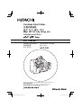
Hitachi CL 14DSL Handling Instructions Manual
- カテゴリー
- パワーツール
- タイプ
- Handling Instructions Manual
このマニュアルも適しています

CL 14DSL
Handling instructions Hướng dẫn sử dụng
คูมือการใชงาน
취급 설명서
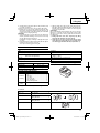
Read through carefully and understand these instructions before use.
본 설명서를 자세히 읽고 내용을 숙지한 뒤 제품을 사용하십시오.
Đọc kỹ và hiểu rõ các hướng dẫn này trước khi sử dụng.
โปรดอานโดยละเอียดและทําความเขาใจกอนใชงาน
Cordless Stud Cutter
충전 전산 볼트 커터
Máy cắt vít cấy dùng pin

2
12
34
56
78
1
#
#
8
9
)
1
2
0
7
6
$ %
w
@
(
u
^
*
&
r
w
e
o
q
t
y
i
(
3
4
1
2
5
!
#

3
910
11 12
13 14
15 16
#
u
*
o
a
p
u
u
s
f
x
h
j
k
l
;
z
o
d
g
w
*
c

4
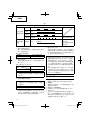
English
한국어
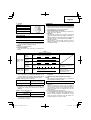
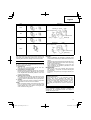
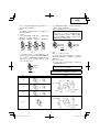
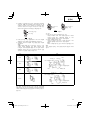
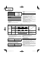
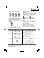
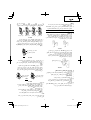
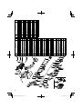
1
Rechargeable battery
충전식 배터리
2
Latch
래치
3
Battery cover
배터리 커버
4
Terminals
단자
5
Ventilation holes
통풍구
6
Handle
핸들
7
Push
누름
8
Insert
삽입
9
Pull out
빼냄
0
Charger
충전기
!
Pilot lamp
충전기 표시등
@
Line
배터리 고정선
#
Forward/reverse switching button
전진/후진 전환 버튼
$
Cutting
절단
%
Lock
잠금
^
Reverse
후진
&
Bracket (A) (movable side)
브라켓 (A) (이동 부분)
*
Hex. socket hd. bolt
육각 구멍붙이 볼트
(
Spacer (used only with M6,M8 or
M10)
스페이서(M6, M8, M10에만 사용)
)
Side without notch
노치가 없는 부분
q
Notch side
노치 부분
w
Bracket (B) (fi xed side)
브라켓 (B) (고정 부분)
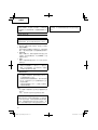
e
Stud guide
전산 볼트 가이드
r
Dial
다이얼
t
Screw size display
볼트 사이즈 디스플레이
y
Mark
마크
u
Stud
전산 볼트
i
Guard section
가드 영역
o
Cutter
커터
p
Correctly mesh
정확한 맞물림
a
Fixed length guide (First cut the stud
to
the required length)
고정 길이 가이드 (먼저 전산 볼트를
필요한 길이로 자름)
s
Stud attachment hole
전산 볼트 부착 구멍
d
Necessary length
필요한 길이
f
Stud suspended from the ceiling
천장에 매달린 전산 볼트
g
Trigger switch
트리거 스위치
h
Hook
훅
j
Latch
래치
k
Grip
그립
l
Entrance
삽입구
;
Pliers
플라이어
z
Remaining battery indicator switch
배터리 잔량 표시 스위치
x
Remaining battery indicator lamp
배터리 잔량 표시등
c
Hex. bar wrench
육각 렌치

5
Tiếng Việt
1
Pin sạc
2
Chốt
3
Nắp pin
4
Đầu cuối
5
Các lỗ thông gió
6
Cầm
7
Đẩy
8
Chèn
9
Kéo ra
0
Bộ sạc
!
Đèn báo
@
Dây dẫn
#
Nút chuyển tiến/lùi
/
$
Cắt
%
Khóa
^
Lùi
&
Ổ đỡ (A) (mặt di động)
(A) ()
*
Bu lông đầu lục giác
(
Miếng đệm (chỉ sử dụng trong M6,
M8 hoặc M10)
( M6,M8 M10
)
)
Mặt không có rãnh chữ V
q
Mặt có rãnh chữ V
w
Ổ đỡ (B) (mặt cố định)
(B) ()
e
Thanh dẫn vít cấy
r
Núm quay số
t
Hiển thị kích thước đinh ốc
y
Mức dấu
u
Vít cấy
i
Khu vực chắn
o
Dao cắt
p
Ăn khớp hoàn toàn
a
Thanh dẫn có chiều dài cố định (Trước
tiên, cắt vít cấy theo chiều dài yêu cầu)
(
)
s
Lỗ gắn vít cấy
d
Chiều dài cần thiết
f
Vít cấy được treo trên trần nhà
g
Công tắc khởi động
h
Móc treo
j
Khóa an toàn
k
Chuôi
l
Đầu vào
;
Kìm
z
Công tắc đèn báo lượng pin còn lại
x
Đèn báo lượng pin còn lại
c
Cờ lê lục giác

English
6
GENERAL SAFETY RULES
WARNING!
Read all instructions
Failure to follow all instructions listed below may result in
electric shock, fi re and/or serious injury.
The term “power tool” in all of the warnings listed below
refers to your mains operated (corded) power tool or battery
operated (cordless) power tool.
SAVE THESE INSTRUCTIONS
1) Work area
a) Keep work area clean and well lit.
Cluttered and dark areas invite accidents.
b) Do not operate power tools in explosive
atmospheres, such as in the presence of
fl ammable liquids, gases or dust.
Power tools create sparks which may ignite the dust
of fumes.
c) Keep children and bystanders away while
operating a power tool.
Distractions can cause you to lose control.
2)
Electrical safety
a) Power tool plugs must match the outlet.
Never modify the plug in any way.
Do not use any adapter plugs with earthed
(grounded) power tools.
Unmodifi ed plugs and matching outlets will reduce
risk of electric shock.
b) Avoid body contact with earthed or grounded
surfaces such as pipes, radiators, ranges and
refrigerators.
There is an increased risk of electric shock if your
body is earthed or grounded.
c) Do not expose power
tools to rain or wet
conditions.
Water entering a power tool will increase the risk of
electric shock.
d) Do not abuse the cord. Never use the cord for
carrying, pulling or unplugging the power tool.
Keep cord away from heat, oil, sharp edges or
moving parts.
Damaged or entangled cords increase the risk of
electric shock.
e) When operating a power tool outdoors, use an
extension cord suitable for outdoor
use.
Use of a cord suitable for outdoor use reduces the
risk of electric shock.
3) Personal safety
a) Stay alert, watch what you are doing and use
common sense when operating a power tool.
Do not use a power tool while you are tired
or under the infl uence of drugs, alcohol or
medication.
A moment of inattention while operating power tools
may result in serious personal injury.
b) Use safety equipment. Always wear eye
protection.
Safety equipment such as dust mask, non-skid
safety shoes, hard hat, or hearing protection used for
appropriate conditions will reduce personal injuries.
c) Avoid accidental starting. Ensure the switch is in
the off position before plugging in.
Carrying power tools with your fi nger on the switch or
plugging in power tools that have the switch on invites
accidents.
d) Remove any adjusting key or wrench before
turning the power tool on.
A wrench or a key left attached to a rotating part of the
power tool may result in personal injury.
e) Do not overreach. Keep proper footing and
balance at all times.
This enables better control of the power tool in
unexpected situations.
f) Dress properly. Do not wear loose
clothing or
jewellery. Keep your hair, clothing and gloves
away from moving parts.
Loose clothes, jewellery or long hair can be caught in
moving parts.
g) If devices are provided for the connection of
dust extraction and collection facilities, ensure
these are connected and properly used.
Use of these devices can reduce dust related
hazards.
4) Power tool use and care
a) Do not force the power tool. Use the correct
power tool for your application.
The correct power tool will do the job better and safer
at the rate for which it was designed.
b) Do not use the power tool if the switch does not
turn it on and off .
Any power tool that cannot be controlled with the
switch is dangerous and must be repaired.
c) Disconnect the plug from the power source
before making any adjustments, changing
accessories, or storing power tools.
Such preventive safety measures reduce the risk of
starting the power tool accidentally.
d) Store idle power tools out of
the reach of children
and do not allow persons unfamiliar with the
power tool or these instructions to operate the
power tool.
Power tools are dangerous in the hands of untrained
users.
e) Maintain power tools. Check for misalignment or
binding of moving parts, breakage of parts and
any other condition that may aff ect the power
tools’ operation.
If
damaged, have the power tool repaired before
use.
Many accidents are caused by poorly maintained
power tools.
f) Keep cutting tools sharp and clean.
Properly maintained cutting tools with sharp cutting
edges are less likely to bind and are easier to control.
g) Use the power tool, accessories and tool bits
etc., in accordance with these instructions and
in the manner intended for the particular type
of power tool, taking into account the working
conditions and
the work to be performed.
Use of the power tool for operations diff erent from
intended could result in a hazardous situation.
5) Battery tool use and care
a) Ensure the switch is in the off position before
inserting battery pack.
Inserting the battery pack into power tools that have
the switch on invites accidents.
b) Recharge only with the charger specifi ed by the
manufacturer.
A charger that is suitable for one type of battery pack
may create a risk of fi re when used with another
battery pack.
c) Use power tools only with specifi cally designated
battery packs.
Use of any other battery packs may create a risk of
injury and fi re.

English
7
d) When battery pack is not in use, keep it away
from other metal objects like paper clips, coins,
keys, nails, screws, or other small metal objects
that can make a connection from one terminal to
another.
Shorting the battery terminals together may cause
burns or a fi re.
e) Under abusive conditions, liquid may be ejected
from the battery; avoid
contact. If contact
accidentally occurs, fl ush with water. If liquid
contacts eyes, additionally seek medical help.
Liquid ejected from the battery may cause irritation or
burns.
6) Service
a) Have your power tool serviced by a qualifi ed
repair person using only identical replacement
parts.
This will ensure that the safety of the power tool is
maintained.
PRECAUTION
Keep children and infi rm persons away.
When not in use, tools should be
stored out of reach of
children and infi rm persons.
PRECAUTIONS FOR CORDLESS STUD CUTTER
1. Never bring the cutter near your fi ngers when operating
the switch.
2. Do not use for cutting screws other than soft steel studs.
This tool is designed especially for cutting of soft steel
studs. Using this tool for brass or stainless steel screws
could cause distortions in the screw threads,
thereby
preventing insertion of nuts.
Never use to cut tempered bolts, screws of diff ering
sizes, reinforcing rods, etc.
3. Use by changing the special cutters according to the size
of the studs. Cutting with cutters of the wrong size could
damage to the continuous thread studs or the cutter
edges.
4. Make sure that the threads on the studs and those on the
cutter are correctly meshed before starting to cut. Cutting
when the threads are not meshed could cause damage
to the studs and the cutter.
5. If the cutter has been attached in the wrong direction or
the bolt
for cutter attachment is loose, this could cause
damage to the cutter edge and could lead to premature
damage to the main unit.
Be very careful to attach the cutter correctly.
6. Cutting studs at short lengths of 10 millimeters or less will
create an insuffi cient meshing length between the
cutter
and studs, thus causing damage to the cutter. Always cut
at lengths of more than 10 millimeters.
7. When cutting studs secured to narrow locations, be sure
that there is at least 8 millimeters between the stud and
the surrounding materials.
If the distance is less than 8 millimeters the
cutter could
contact the surrounding materials, thereby causing
damage to the cutter and the main unit.
8. When inspecting, cleaning or replacing the cutter, be
sure to remove the battery from the main unit. The
switch could be turned on accidentally, thereby causing
accidents.
9. When using this equipment at heights,
make doubly
sure prior to use that there is no one standing in the
area immediately below you. Place the tool in a safe and
stable place when not using at the moment.
10. Always charge the battery at a temperature of 0 – 40°C.
A temperature of less than 0°C will result in over charging
which is dangerous. The battery cannot be charged at
a temperature greater than 40°C. The most suitable
temperature for charging is that of 20 – 25°C.
11. Do
not use the charger continuously.
When one charging is completed, leave the charger for
about 15 minutes before the next charging of battery.
12. Do not allow foreign matter to enter the hole for
connecting the rechargeable battery.
13. Never disassemble the rechargeable battery and
charger.
14. Never short-circuit the rechargeable battery.
Short-
circuiting the battery will cause a great electric current
and overheat. It results in burn or damage to the battery.
15. Do not dispose of the battery in fi re.
If the battery is burnt, it may explode.
16. Do not insert object into the air ventilation slots of the
charger.
Inserting
metal objects or infl ammables into the charger
air ventilation slots will result in electrical shock hazard or
damaged charger.
17. Bring the battery to the shop from which it was purchased
as soon as the post-charging battery life becomes too
short for practical use. Do not dispose of the exhausted
battery.
18. Using an exhausted battery will damage the charger.
CAUTION ON LITHIUM-ION BATTERY
To extend the lifetime, the lithium-ion battery equips with the
protection function to stop the output.
In the cases of 1 and 2 described below, when using this
product, even if you are pulling the switch, the motor may
stop. This is not the trouble but the result of protection
function.
1.
When the battery power remaining runs out, the motor
stops.
In such case, charge it up immediately.
2. If the tool is overloaded, the motor may stop. In this
case, release the switch of tool and eliminate causes of
overloading. After that, you can use it again.
Furthermore, please heed the
following warning and caution.
WARNING
In order to prevent any battery leakage, heat generation,
smoke emission, explosion and ignition beforehand, please
be sure to heed the following precautions.
1. Make sure that swarf and dust do not collect on the
battery.
○ During work make sure that swarf and dust do not fall
on
the battery.
○ Make sure that any swarf and dust falling on the power
tool during work do not collect on the battery.
○ Do not store an unused battery in a location exposed to
swarf and dust.
○ Before storing a battery, remove any swarf and dust that
may adhere
to it and do not store it together with metal
parts (screws, nails, etc.).
2. Do not pierce battery with a sharp object such as a
nail, strike with a hammer, step on, throw or subject the
battery to severe physical shock.
3. Do not use an apparently damaged or deformed battery.
4. Do not use the battery in reverse polarity.
5. Do not connect directly to an electrical outlets or car
cigarette lighter sockets.
6. Do not use the battery for a purpose other than those
specifi ed.
7. If the battery charging fails to complete even when a
specifi ed recharging time
has elapsed, immediately stop
further recharging.

English
8
3. If you fi nd rust, foul odor, overheating, discolor,
deformation, and/or other irregularities when using the
battery for the fi rst time, do not use and return it to your
supplier or vendor.
WARNING
If an electrically conductive foreign object enters the terminals
of the lithium ion battery, a short-circuit may occur resulting
in the risk of fi re. Please observe the following matters when
storing the battery.
○ Do not place electrically conductive cuttings, nails,
steel wire, copper wire or other wire in the storage
case.
○ Either install the battery in the power tool or store
by securely pressing into the battery cover until the
ventilation holes are concealed to prevent short-
circuits (See Fig. 1).
8. Do not put or subject the battery to high temperatures or
high pressure such as into a microwave oven, dryer, or
high pressure container.
9. Keep away from fi re immediately when leakage or foul
odor are detected.
10. Do not
use in a location where strong static electricity
generates.
11. If there is battery leakage, foul odor, heat generated,
discolored or deformed, or in any way appears abnormal
during use, recharging or storage, immediately remove it
from the equipment or battery charger, and stop use.
CAUTION
1. If liquid leaking from the battery
gets into your eyes, do not
rub your eyes and wash them well with fresh clean water
such as tap water and contact a doctor immediately.
If left untreated, the liquid may cause eye-problems.
2. If liquid leaks onto your skin or clothes, wash well with
clean water such as tap
water immediately.
There is a possibility that this can cause skin irritation.
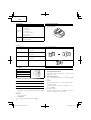
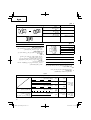
SPECIFICATIONS
POWER TOOL
Model CL14DSL
No-load stroke 30 /min
Capacity:
Soft steel studs
(Size of studs for cutting)
○ M10 × 1.5 ○ M8 × 1.25 ○ M6 × 1
○ W3/8" × 1.5875
Rechargeable battery BSL1430: Li-ion 14.4 V (3.0 Ah 8 cells)
Weight 2.9 kg
CHARGER
Model UC18YRSL
Charging voltage 14.4 V – 18 V
Weight 0.6 kg
STANDARD ACCESSORIES
CL14DSL
(2LSCK)
1
Charger ................................................ 1
2
Battery ................................................. 2
3
Battery cover ........................................ 1
4
Plastic case .......................................... 1
5
Hexagonal bar wrench ......................... 1
6
W3/8" Cutter ........................................ 2
7
W3/8" Trimmer ..................................... 1
CL14DSL
(NN)
Without charger, battery, battery cover and
plastic case
Standard accessories are subject to change without notice.
OPTIONAL ACCESSORIES (sold separately)
1. Battery (BSL1430)
2. Cutter
Screw size Combining cutters and spacers
M10 × 1.5 M10 Cutter ....................................2
M10 Spacer ..................................2
M8 × 1.25 M8 Cutter ......................................2
M8 Spacer ....................................2
M6 × 1M6 Cutter ......................................2
M6 Spacer ....................................2
W3/8" × 1.5875 W3/8" Cutter .................................2

English
9
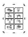
CHARGING
Before using the power tool, charge the battery as follows.
1. Connect the charger’s power cord to the receptacle.
When the power cord is connected, the charger’s pilot
lamp will blink in red. (At 1-second intervals)
2. Insert the battery into the charger
Firmly insert the battery into the charger until the
line is
visible, as shown in Fig. 3, 4.
3. Charging
When inserting a battery in the charger, charging will
commence and the pilot lamp will light continuously in
red.
When the battery becomes fully recharged, the pilot lamp
will blink in red. (At 1-second intervals). (See Table 1)
(1)
Pilot lamp indication
The indications of the pilot lamp will be as shown in
Table 1, according to the condition of the charger or the
rechargeable battery.
3. Trimmer
Screw size
M10 × 1.5
M8 × 1.25
M6 × 1
W3/8" × 1.5875
Optional accessories are subject to change without notice.
APPLICATIONS
○ Cutting of soft steel studs.
BATTERY REMOVAL/INSTALLATION
1. Battery removal
Hold the handle tightly and push the battery latch to
remove the battery (see Figs. 1 and 2).
CAUTION
Never short-circuit the battery.
2. Battery installation
Insert the battery while observing its polarities (see
Fig. 2).
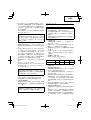
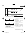
Table 1
Indications of the pilot lamp
The pilot lamp
lights or blinks
in red.
Before
charging
Blinks
Lights for 0.5 seconds. Does not light for 0.5
seconds. (off for 0.5 seconds)
While
charging
Lights
Lights continuously
Charging
complete
Blinks
Lights for 0.5 seconds. Does not light for 0.5
seconds. (off for 0.5 seconds)
Charging
impossible
Flickers
Lights for 0.1 second. Does not light for 0.1
seconds. (off for 0.1 seconds)
Malfunction in the battery or
the charger.
The pilot lamp
lights in green.
Overheat
standby
Lights
Lights continuously
Battery overheated.
Unable to charge
(Charging will commence
when battery cools).
(2) Regarding the temperature of the rechargeable battery
The temperatures for rechargeable batteries are as
shown in Table 2, and batteries that have become hot
should be cooled for a while before being recharged.
Table 2 Recharging ranges of batteries
Rechargeable batteries
Temperatures at which the
battery can be recharged
BSL1430 0°C – 40°C
(3) Regarding recharging time
Depending on the combination of the charger and
batteries, the charging time will become as shown in
Table 3.
Table 3 Charging time (At 20°C)
Charger
Battery
UC18YRSL
BSL1430 Approx. 45 min.
NOTE:
The charging time may vary according to temperature
and power source voltage.
4. Disconnect the charger’s power cord from the
receptacle
5. Hold the charger fi rmly and pull out the battery
NOTE:
After charging, pull out batteries from the charger fi rst,
and then keep the batteries properly.
How to make the batteries perform longer.
(1) Recharge the batteries before they become completely
exhausted.
When you feel that the power of the tool becomes
weaker, stop using the tool and recharge its battery. If
you continue to use the tool and exhaust the electric
current, the battery may be
damaged and its life will
become shorter.
(2) Avoid recharging at high temperatures.
A rechargeable battery will be hot immediately after use.
If such a battery is recharged immediately after use, its
internal chemical substance will deteriorate, and the
battery life will be shortened. Leave the battery and
recharge it after
it has cooled for a while.

English
10
1 When using the M10, M8 or M6 cutter
Check and confi rm that the accessory M6, M8 or M10
spacers are correctly inserted respectively between
bracket (A) and the cutter and bracket (B) and the cutter
(Fig. 6).
CAUTION
If the spacers are not attached or if spacers of
the wrong
size are used, the threads of the cutter and the studs will
not properly mesh, thereby causing damage to the studs
and the cutter edge. Be sure to attach spacers correctly.
2 When using the W3/8" cutter
No spacers are required. Check and confi rm that only the
cutter
is attached.
For details, refer to the section on “Cutter life and
replacement”.
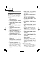
5. Correctly insert the stud guide
The stud guide is used to prevent tilting during cutting of
studs. Correctly adjust the dial calibration to the mark (
△)
depending on the size of the stud to be cut (Fig. 7).
CAUTION
If the size of the stud and the dial position to do not agree,
the cut section may be subjected to burrs or its shape
may be distorted, which may result in damage to the main
unit.
HOW TO USE
CAUTION
○ Never bring the cutter near your fi ngers when operating
the trigger switch.
○ When cutting short studs, take caution as to not place
your fi ngers in the space between the short stud and
main unit, such as the guard section (see Fig. 8), battery,
etc.
○ After cutting, the cut
section of the stud is very sharp and
therefore dangerous. Be very careful when handling the
stud.
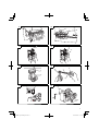
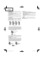
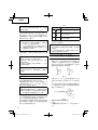
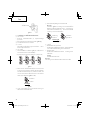
1. Normal Cutting Method
(1) Pull the trigger switch and move bracket (A), stopping
with the cutter in the open position shown in Fig. 8.
(2) As shown in Fig. 9, set the stud
to be cut in the cutter
on the bracket (B) side, making sure that the threads
correctly mesh with each other.
(3) While maintaining the stud in a horizontal position, pull
the trigger switch all the way to cut the stud (Fig. 8).
(4) After cutting turn off the switch
with bracket (A) facing
directly upward. The unit stops with the cutter in the open
position, thus making it easier to proceed to the next
operation.
2. Number of cuttings (per battery charging)
Refer to the chart below for the number of cuttings per
battery charging.
Table 4
Battery M10 M8 M6 W3/8"
BSL1430 660 1020 1520 740
The number of cuttings can also vary somewhat
according to the ambient temperature, characteristics of
the battery and the condition of the cutter.
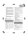
3. Cutting fi xed lengths (Fig. 10)
When cutting several studs to the same length, using
the equipment in the following way will making cutting
operations more
effi cient.
(1) First cut one stud to the required length, and then use it
as a fi xed length guide.
CAUTION
○ When the battery charger has been continuously used,
the battery charger will be heated, thus constituting
the cause of the failures. Once the charging has been
completed, give 15 minutes rest until the next charging.
○ If the battery is recharged when it is warm due to battery
use or
exposure to sunlight, the pilot lamp may light in
green.
The battery will not be recharged. In such a case, let the
battery cool before charging.
○ When the pilot lamp fl ickers in red (at 0.2-second
intervals), check for and take out any foreign objects
in the charger’s battery installation hole.
If there are no
foreign objects, it is probable that the battery or charger
is malfunctioning. Take it to your authorized Service
Center.
PRIOR TO OPERATION
1. Preparing and checking the work environment
Make sure that the work site meets all the conditions laid
forth in the precautions.
2. Checking the battery
Make sure that the battery is installed fi rmly. If it is at all
loose it could come off and cause an accident.
3. Setting the
forward/reverse switching button
(1) Push the forward/reverse switching button from the right
as shown in Fig. 5 (a). Cutting is possible.
(2) By setting the forward/reverse switching button in the
lock position as shown in Fig. 5 (b), the motor will not
operate even if the trigger switch is pulled. When
carrying
or storing the main unit or when stopping operations, set
the forward/reverse switching button to the lock position
(Fig. 5 (b)).
(3) Push the forward/reverse switching button from the left
as shown in Fig. 5 (c). With the button held down, pull
the trigger switch so that the
cutter can be removed from
the stud. Only set to this position if the rechargeable
battery is worn out and the unit stops operating during
cutting. Immediately turn off the switch after the cutter
has been removed from the stud.
If you remove your fi nger, the forward/reverse switching
button automatically
returns to the lock position (Fig. 5
(b)).
CAUTION
Do not attempt to cut in the reverse position (Fig. 5 (c)).
If you attempt to cut in this position, there will be an
overload on the motor and cutting will not be possible.
Never apply excessive force to the
main unit as this can
cause damage to the unit.
4. Check the cutter size, attachment direction,
attachment bolt and spacer
(1) The cutter size diff ers according to the size of the studs to
be cut. Make sure that a cutter is attached that conforms
to the size of the
studs to be cut.
(2) Cutter attachment includes directionality. Make sure that
the cutter has been attached so that the side without the
notch on the cutter can be seen on bracket (A) (movable
side) when the main unit is viewed from the front or that
the notch on the cutter
surface can be seen on bracket
(B) (fi xed side).
(3) Use the accessory hexagonal wrench to insure that the
hex. socket hd. bolt for attaching the cutter is securely
tightened (Fig. 6). Using the equipment while the bolt is
loose could cause damage to the main unit and cutter.
(4)
Depending on the size of the studs it may be necessary
to attach special spacers to the cutter.

English
11
(2) Insert the stud used as a fi xed length guide in the stud
attachment hole found on the main unit stud guide and
use the hexagonal bar wrench to tighten and secure
the hex. socket hd. bolt. Adjust at this time so that the
distance between the end of the stud
used as a fi xed
length and the cutter is the necessary length.
(3) Insert the stud for cutting in the cutter, aligning the end
with that of the stud used as a cutting guide, and then cut
the stud.
4. Cutting studs that are already secured (Fig. 11)
When cutting studs
that are suspended from the ceiling
or secured to walls or fl oors.
When inserting the stud in the cutter, the meshing of
the stud thread and cutter thread is unstable. In such
a case, after inserting the stud in the cutter, lightly pull
the trigger switch to close the cutter at
low speed and
then completely mesh the stud and the upper and lower
cutters. Next, pull the trigger switch all the way to cut the
stud.
CAUTION
Use your one hand to hold the stud on the side released
by cutting to insure that it does not fall unexpectedly.
5. Removing the
screw from the unit during cutting
operations
If the battery wears out during cutting operations so that
the motor stops rotating, pull the trigger switch while
pushing the forward/reverse switching button to the
reverse side (Fig. 5 (c)). The motor will rotate in the
opposite direction and it will
be possible to remove the
stud from the cutter(Fig. 12).
CAUTION
○ When removing a stud that is suspended from the
ceiling, hold the main unit with both hands to prevent
any possibility of the stud falling.
○ Immediately turn off the switch once the cutter is free
from the stud.
If you attempt to do this with the switch
turned on, the cutter might cut into the stud again.
6. Using the hook
The hook can be used to hang up the unit temporarily
during operations (Fig. 13).
CAUTION
The hook should never be used to hang the unit on your
person.
When using the hook, check to make sure that the main
unit will not slip and fall, or become unstable by the wind,
etc.
Never hang the unit from your belt or trousers as this
could cause accidents.
NOTE:
During normal use or during storage, store the hook in the
latch found on the bottom of the main unit.
7. Using the trimmer
NOTE: Use a special trimmer that is suitable for the size
of the stud.
If it is diffi cult for the nut to enter the cutting position,
either use a wrench to fi rmly tighten the nut or
use the
accessory trimmer to remove the fl ange on the screw
thread.
Insert the stud in the hole on the grip. Use a pliers to
retain the stud and rotate the trimmer 5 or 6 times to the
right to remove the fl ange and then rotate in the opposite
direction to
remove the trimmer (Fig. 14).
CAUTION
This trimmer is specially designed for Studs Cutter. The
fl ange on studs cut with a hacksaw or disc grinder is too
large for this trimmer so that the trimmer does not rotate
and it is not possible to remove fl ange.
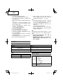
8. About Remaining Battery Indicator
When pressing the remaining battery indicator switch,
the remaining battery indicator lamp lights and the
battery remaining power can be checked. (Fig. 15) When
releasing your fi nger from the remaining battery indicator
switch, the remaining battery indicator lamp goes off . The
Table 5
shows the state of remaining battery indicator
lamp and the battery remaining power.
Table 5
State of lamp Battery Remaining Power
The battery remaining power is
enough.
The battery remaining power is a half.
The battery remaining power is nearly
empty.
Re-charge the battery soonest
possible.
As the remaining battery indicator shows somewhat
diff erently depending on ambient temperature and
battery characteristics, read it as a reference.
NOTE:
○ Do not give a strong shock to the switch panel or break
it.It may lead to a trouble.
○ To save the battery power consumption, the remaining
battery indicator lamp lights while pressing the remaining
battery indicator switch.
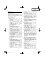
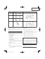
CUTTER LIFE AND REPLACEMENT
1. Cutter life
As is shown in Fig. 17, repeated cutting can cause
breaking and warping of the cutter edge. Using the
cutter in this condition can produce fl ange on the cutting
location of the studs so that the threads are distorted.
This will prevent clean cuts and make it
impossible to
insert the nut.
Breaking Warping
Fig. 17
As is shown in Fig. 18, the edge is found on four locations
on the cutter. Use the method described below to change
the attachment direction of the cutter to allow a total of
four usages.
If the nut does not fi t on the screw due to breaking
and
warping of the edge, change the cutter attachment
direction to use the edge without breaking and warping
or replace with a new cutter.
Four edges
on the cutter
Fig. 18

English
12
2. Changing the cutter attachment direction or
replacing the cutter
(1) Before removing:
1 Pull the trigger switch and move bracket (A), stopping
with the cutter in the open position.
2 Set the forward/reverse switching button to the lock
position (Fig. 5 (b)).
3 Remove the rechargeable battery from the main unit.
(2) Removal
Use the accessory hexagonal bar wrench to remove the
hex. socket hd. bolt. It is now possible to remove the
cutter and spacer.
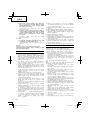
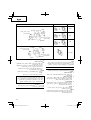
(3) Before attaching
1 There are four edges on the cutter. As shown in Fig. 19,
by changing the position of the edge it is possible
to use
the blade four times.
1st time
2nd time 3rd time 4th time
( )
Turning to
the back side
( )
Re-
insertion
( )
Turning to
the back side
( )
Turning to
the back side
Fig. 19
2 There is directionality for cutter attachment in order to
change the position of the edge. Check that the cutter
has been attached so that the side without the notch on
the cutter can be seen on bracket (A) (movable side)
when seen from the main unit viewed from
the front or
that the notch on the cutter surface on bracket (B) (fi xed
side) can be seen (Figs. 6 and 20).
Side without notch
Notch side
DO
Fig. 20
3 If there is breakage or warping on the cutter edge or if
there are bulges on the cutter attachment surface, use a
fi le to the areas fl at.
4 Use brush to remove the fi lings attached to the cutter
attachment groove on the bracket.
CAUTION
As shown in Fig.
21, if the cutters are combined in such
a way that both side without the notch on the cutter or
both notch sides are facing out, the pitch of the threads
on the studs and the threads on the cutter will not be in
agreement. This can cause damage to
the cutter edge or
cause wear to premature damage to the main unit.
DON’T
Both on
notch side
Both on
side without
notch
Fig. 21
(4) Attachment
1 When using an M6, M8 or M10 cutter
Insert the cutter in the cutter attachment groove on the
bracket, insert the special spacer between the cutter
and the bracket and then use the hex. socket hd. bolt to
tighten
and secure.
2 When using the W3/8" cutter
Insert the cutter in the cutter attachment groove on the
bracket and then use the hex. socket hd. bolt to tighten
and secure.
NOTE:
Spacers are not required when using the W3/8" cutter.
CAUTION
The hex. socket hd. bolt should be suffi ciently tightened
with
the hexagonal wrench.

English
13
Size Attachment
M10
Hex. socket hd. bolt
Bracket (A)
Spacer
Cutter
Hex. socket hd. bolt
Bracket (B)
Spacer
Cutter
M8
M6
W3/8"
Hex. socket hd. bolt
Bracket (A) Cutter
Hex. socket hd. bolt
Bracket (B)
Cutter
CAUTION
Use special cutters and spacers that conform with the size
of the stud. Using cutters and spacers of the wrong size or
confusing them can lead to damage to the stud and cutter.
MAINTENANCE AND INSPECTION
CAUTION
Be sure to remove the rechargeable battery from the unit
during inspection and cleaning.
1. Care after use
After use, use a brush to brush off the work area,
especially the area around the blade.
2. Inspecting the mounting screws
Regularly inspect all mounting screws and ensure that
they are properly
tightened. Should any of the screws be
loose, retighten them immediately. Failure to do so could
result in serious hazard.
3. Cleaning on the outside
When the power tool is stained, wipe with a soft dry cloth
or a cloth moistened with soapy water. Do not use chloric
solvents, gasoline or
paint thinner, for they melt plastics.
4. Storage
Store the power tool in a place in which the temperature
is less than 40°C and out of reach of children.
NOTE:
Make sure that the battery is fully charged when stored
for a long period (3 months or more). The battery with
smaller
capacity may not be able to be charged when
used, if stored for a long period.
5. Service parts list
CAUTION
Repair, modifi cation and inspection of Hitachi Power
Tools must be carried out by a Hitachi Authorized Service
Center.
This Parts List will be helpful if presented with the tool to
the Hitachi Authorized Service Center when requesting
repair or other maintenance.
In the operation and maintenance of power tools, the
safety regulations and standards prescribed in each
country must be observed.
MODIFICATIONS
Hitachi Power Tools are constantly being improved
and modifi ed to incorporate the latest technological
advancements.
Accordingly, some parts
may be changed without prior
notice.
Important notice on the batteries for the Hitachi
cordless power tools
Please always use one of our designated genuine
batteries. We cannot guarantee the safety and
performance of our cordless power tool when used with
batteries other than these designated by us, or when
the battery is disassembled and modifi ed
(such as
disassembly and replacement of cells or other internal
parts).
NOTE
Due to HITACHI’s continuing program of research and
development, the specifi cations herein are subject to
change without prior notice.

14

15

16
1
2
3
4
5
6
7

17

18

19
1
2

20
1
ページが読み込まれています...
ページが読み込まれています...
ページが読み込まれています...
ページが読み込まれています...
ページが読み込まれています...
ページが読み込まれています...
ページが読み込まれています...
ページが読み込まれています...
ページが読み込まれています...
ページが読み込まれています...
ページが読み込まれています...
ページが読み込まれています...
ページが読み込まれています...
ページが読み込まれています...
ページが読み込まれています...
ページが読み込まれています...
ページが読み込まれています...
ページが読み込まれています...
ページが読み込まれています...
ページが読み込まれています...
ページが読み込まれています...
ページが読み込まれています...
ページが読み込まれています...
ページが読み込まれています...
ページが読み込まれています...
ページが読み込まれています...
ページが読み込まれています...
ページが読み込まれています...
ページが読み込まれています...
ページが読み込まれています...
ページが読み込まれています...
ページが読み込まれています...
ページが読み込まれています...
ページが読み込まれています...
ページが読み込まれています...
ページが読み込まれています...
ページが読み込まれています...
ページが読み込まれています...
ページが読み込まれています...
ページが読み込まれています...
-
 1
1
-
 2
2
-
 3
3
-
 4
4
-
 5
5
-
 6
6
-
 7
7
-
 8
8
-
 9
9
-
 10
10
-
 11
11
-
 12
12
-
 13
13
-
 14
14
-
 15
15
-
 16
16
-
 17
17
-
 18
18
-
 19
19
-
 20
20
-
 21
21
-
 22
22
-
 23
23
-
 24
24
-
 25
25
-
 26
26
-
 27
27
-
 28
28
-
 29
29
-
 30
30
-
 31
31
-
 32
32
-
 33
33
-
 34
34
-
 35
35
-
 36
36
-
 37
37
-
 38
38
-
 39
39
-
 40
40
-
 41
41
-
 42
42
-
 43
43
-
 44
44
-
 45
45
-
 46
46
-
 47
47
-
 48
48
-
 49
49
-
 50
50
-
 51
51
-
 52
52
-
 53
53
-
 54
54
-
 55
55
-
 56
56
-
 57
57
-
 58
58
-
 59
59
-
 60
60


Hitachi CL 14DSL Handling Instructions Manual
- カテゴリー
- パワーツール
- タイプ
- Handling Instructions Manual
- このマニュアルも適しています
関連論文
-
Hitachi CS 33EB Handling Instructions Manual
-
Hitachi P14DSL Handling Instructions Manual
-
-
Hitachi CJ 18DSL Handling Instructions Manual
-
-
-
Hitachi WH 18DBEL Handing Instructions
-
Hikoki WR 14DSDL ユーザーマニュアル
-
-