
SONY CDX-GT47U (GB,CS) 3-275-443-51 (1)SONY CDX-GT47U (GB,CS) 3-275-443-51 (1)
L
R
REAR/SUB
AUDIO OUT
REAR
/
SUB
AU
DIO OUT
*
2
2
4
5
1
3
REMOTE
IN
3-275-443-51 (1)
Cautions
• This unit is designed for negative ground (earth) 12 V
DC operation only.
• Do not get the leads under a screw, or caught in moving
parts (e.g. seat railing).
• Before making connections, turn the car ignition off to
avoid short circuits.
• Connect the yellow
and red power supply leads only
after all other leads have been connected.
• Run all ground (earth) leads to a common
ground (earth) point.
• Be sure to insulate any loose unconnected leads with
electrical tape for safety.
Notes on the power supply lead (yellow)
• When connecting this unit in combination with other
stereo components, the connected car circuit’s rating
must be higher than the sum of each component’s fuse.
• When no car circuits are rated high enough, connect
the unit directly to the battery.
Parts Iist
• The numbers in the list are keyed to those in the
instructions.
• The bracket
and the protection collar are
attached to the unit before shipping. Before mounting
the unit, use the release keys
to remove the bracket
and the protection collar from the unit. For
details, see “Removing the protection collar and the
bracket (
)” on the reverse side of the sheet.
• Keep the release keys for future use as they
are also necessary if you remove the unit from
your car.
Caution
Handle the bracket
carefully to avoid injuring your
fingers.
Note
Before installing, make sure that the catches on both sides of
the bracket
are bent inwards 2 mm (
3
/32 in). If the catches are
straight or bent outwards, the unit will not be installed securely
and may spring out.
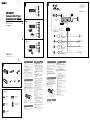
Connection example
Notes (-
B
)
• Be sure to connect the ground (earth) lead before connecting
the amplifier.
• The alarm will only sound if the built-in amplifier is used.
Installation/Connections
安装/线路连接
FM/MW/SW
Compact Disc Player
Connection diagram
To a metal surface of the car
First connect the black ground (earth) lead, then connect the
yellow and red power supply leads.
To the power antenna (aerial) control lead or
power supply lead of antenna (aerial) booster
Notes
• It is not necessary to connect this lead if there is no power
antenna (aerial) or antenna (aerial) booster, or with a
manually-operated telescopic antenna (aerial).
• When your car has a built-in FM/MW/SW antenna (aerial)
in the rear/side glass, see “Notes on the control and power
supply leads.”
To AMP REMOTE IN of an optional power
amplifier
This connection is only for amplifiers. Connecting any other
system may damage the unit.
To the +12 V power terminal which is
energized in the accessory position of the
ignition switch
Notes
• If there is no accessory position, connect to the +12 V
power (battery) terminal which is energized at all times.
Be sure to connect the black ground (earth) lead to a
metal surface of the car first.
• When your car has a built-in FM/MW/SW antenna (aerial)
in the rear/side glass, see “Notes on the control and power
supply leads.”
To the +12 V power terminal which is
energized at all times
Be sure to connect the black ground (earth) lead to a metal
surface of the car first.
Notes on the control and power supply leads
• The power antenna (aerial) control lead (blue) supplies +12 V
DC when you turn on the tuner.
• When your car has built-in FM/MW/SW antenna (aerial) in the
rear/side glass, connect the power antenna (aerial) control
lead (blue) or the accessory power supply lead (red) to the
power terminal of the existing antenna (aerial) booster. For
details, consult your dealer.
• A power antenna (aerial) without a relay box cannot be used
with this unit.
Memory hold connection
When the yellow power supply lead is connected, power will
always be supplied to the memory circuit even when the ignition
switch is turned off.
Notes on speaker connection
• Before connecting the speakers, turn the unit off.
• Use speakers with an impedance of 4 to 8 ohms, and with
adequate power handling capacities to avoid its damage.
• Do not connect the speaker terminals to the car chassis, or
connect the terminals of the right speakers with those of the
left speaker.
• Do not connect the ground (earth) lead of this unit to the
negative (–) terminal of the speaker.
• Do not attempt to connect the speakers in parallel.
• Connect only passive speakers. Connecting active speakers
(with built-in amplifiers) to the speaker terminals may damage
the unit.
• To avoid a malfunction, do not use the built-in speaker leads
installed in your car if the unit shares a common negative (–)
lead for the right and left speakers.
• Do not connect the unit’s speaker leads to each other.
Note on connection
If speaker and amplifier are not connected correctly, “FAILURE”
appears in the display. In this case, make sure the speaker and
amplifier are connected correctly.
REAR
/
SUB
AUDIO OUT
A
B
Equipment used in illustrations (not supplied)
插图中的装置(非附送)
from car antenna (aerial)
来自汽车天线
Rear speaker
后置扬声器
Front speaker
前置扬声器
Active subwoofer
有源超重低音扬声器
Power amplifier
功率放大器
Catch
× 2
× 4
REAR
/
SUB
AUDIO OUT
注意
• 本机只能使用负极接地的 12 V 直流电源。
• 勿使导线夹在螺丝下,或缠在移动部件上(如座椅
扶手)。
• 连接线路之前,请关闭汽车点火开关,以避免短
路。
• 只有连接了所有其他导线之后,再连接黄色和红色
电源导线。
• 将所有地线都连接到同一接地点。
• 为了安全,请务必用绝缘胶带使所有松散未连接的
导线绝缘。
关于电源导线(黄色)的注意事项
• 将本机与其它立体声装置组合使用时,所连接的汽
车电路容量必须大于各装置保险丝容量的总和。
• 当汽车电路容量不够大时,请将本机直接与蓄电池
相连接。
零件一览表
• 表中数字与说明书中的数字是一致的。
• 装卸支架 和保护环 是出厂前装在本装置
上的。安装本装置之前,使用开锁钥匙 从本
装置上取下装卸支架 和保护环 。详细内
容,请参阅本页反面的“拆卸保护环和装卸支架
()”。
• 您从汽车上取下本装置时,有必要用到该钥匙,因
此保存好开锁钥匙 以备后用。
注意
小心使用装卸支架
以免伤到手指。
固定片
注
安装前,请确认装卸支架
两边的固定片向内弯曲 2 mm。如果
固定片笔直或向外弯曲,本装置将不能牢固安装并可能弹出。
线路连接图例
注 (-B)
• 务必在连接放大器之前连接地线。
• 只有在使用内置的放大器时,警报器才会发出声响。
线路连接图
至汽车金属表面
首先连接黑色地线,然后连接黄色和红色电源导线。
至电动天线控制导线或天线升缩器的电源导线
注
• 如果没有电动天线或天线升缩器,或有手动伸缩式天线,
则无需连接此导线。
• 若汽车的后/侧玻璃窗内有内置 FM/MW/SW 天线,请参
阅“关于控制导线和电源导线的注意事项”。
至选购的功率放大器的 AMP REMOTE IN
此连接仅适用于放大器。连接其它系统可能损坏本机。
至 +12 V 电源端子,该端子在点火开关附件位置
通电
注
• 如果没有附件位置,则连接至 +12 V 电源(蓄电池)端
子,该端子随时处于通电状态。
确保首先将黑色地线连接至汽车金属表面。
• 若汽车的后/侧玻璃窗内有内置 FM/MW/SW 天线,请参
阅“关于控制导线和电源导线的注意事项”。
至 +12 V 电源端子,该端子随时处于通电状态
确保首先将黑色地线连接至汽车金属表面。
关于控制导线和电源导线的注意事项
• 接通调谐器电源时,电动天线的控制导线(蓝色)便能提供
+12 V 直流电。
• 当汽车的后/侧玻璃窗上有内置 FM/MW/SW 天线时,请将电动天
线控制线(蓝色)或辅助电源导线(红色)连接至现有天线升
缩器上的电源端子上。详细说明,请与您的经销商联系。
• 本机不能使用不具备继电器盒的电动天线。
保持记忆的线路连接法
当连接了黄色的电源导线时,即使点火开关关闭,电源仍将对记
忆电路供电。
关于扬声器连接的注意事项
• 连接扬声器之前,请关闭本机电源。
• 请使用阻抗为 4-8 欧姆且具有足够功率处理容量的扬声器,以
免损坏。
• 勿将扬声器端子连接到汽车底盘上,或将右扬声器的端子与左
扬声器的端子连接。
• 勿将本机的地线连接到扬声器的负极(-)端子上。
• 扬声器不可并联连接。
• 请仅连接无源扬声器。将有源扬声器(具有内置放大器)连接
到扬声器端子可能会损坏本机。
• 若本机使用左、右扬声器的共用负极(-)导线,为了避免故
障,切勿使用安装在汽车内的内置扬声器导线。
• 请勿将本机扬声器导线相互连接。
连接的注意事项
如果未正确连接扬声器和放大器,则显示屏上会出现
“FAILURE”。这时,请确保扬声器和放大器连接正确。
*
1
RCA pin cord (not supplied)
*
2
AUDIO OUT can be switched SUB or
REAR. For details, see the supplied
Operating Instructions.
*
3
Insert with the cord upwards.
*
1
RCA 针导线(非附送)
*
2
AUDIO OUT 可切换至 SUB 或 REAR。详细内
容,请参阅附带的使用说明书。
*
3
电线向上插入。
AMP REM
Max. supply current 0.3 A
最大电流 0.3 A
Fuse (10 A)
保险丝 (10 A)
Blue/white striped
蓝色/白色条纹
Red
红色
Yellow
黄色
White
白色
Green
绿色
Purple
紫色
White/black striped
白色/黑色条纹
Grey/black striped
灰色/黑色条纹
Green/black striped
绿色/黑色条纹
Grey
灰色
Left
左
Right
右
Left
左
Right
右
ANT REM
Black
黑色
Blue
蓝色
Max. supply current 0.1 A
最大电流 0.1 A
Purple/black striped
紫色/黑色条纹
*
1
CDX-GT47U
©
2007 Sony Corporation Printed in Thailand
Rotary commander RM-X4S
旋转式控制器 RM-X4S
*
3

SONY CDX-GT47U (GB,CS) 3-275-443-51 (1)SONY CDX-GT47U (GB,CS) 3-275-443-51 (1)
1
2 3
182 mm
53 mm
Dashboard
仪表板
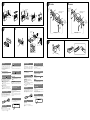
A TOYOTA
to dashboard/center console
至仪表板/中央控制箱
Bracket
装卸支架
Bracket
装卸支架
B NISSAN
to dashboard/center console
至仪表板/中央控制箱
Bracket
装卸支架
Bracket
装卸支架
Existing parts supplied with your car
随汽车附送的现有部件
A
B
1
2
max. size
5 × 8 mm
(
7
/32 ×
11
/32 in)
最大尺寸
5×8 mm
max. size
5 × 8 mm
(
7
/32 ×
11
/32 in)
最大尺寸
5×8 mm
max. size
5 × 8 mm
(
7
/32 ×
11
/32 in)
最大尺寸
5×8 mm
max. size
5 × 8 mm
(
7
/32 ×
11
/32 in)
最大尺寸
5×8 mm
Face the hook
inwards.
钩子面向内。
Claws
卡爪
Mounting the unit in a Japanese
car
You may not be able to install this unit in some makes of
Japanese cars. In such a case, consult your Sony dealer.
Note
To prevent malfunction, install only with the supplied screws
.
How to detach and attach the
front panel
Before installing the unit, detach the front panel.
-A To detach
Before detaching the front panel, be sure to press .
Press , and pull it off towards you.
-B To attach
Engage part of the front panel with part of the unit,
as illustrated, and push the left side into position until it
clicks.
Warning if your car’s ignition
has no ACC position
Be sure to set the Auto Off function. For details, see the
supplied Operating Instructions.
The unit will shut off completely and automatically in
the set time after the unit is turned off, which prevents
battery drain.
If you do not set the Auto Off function, press and hold
until the display disappears each time you turn
the ignition off.
RESET button
When the installation and connections are completed,
be sure to press the RESET button with a ball-point pen,
etc., after detaching the front panel.
Precautions
• Choose the installation location carefully so that the
unit will not interfere with normal driving operations.
• Avoid installing the unit in areas subject to dust, dirt,
excessive vibration, or high temperatures, such as in
direct sunlight or near heater ducts.
• Use only the supplied mounting hardware for a safe
and secure installation.
Mounting angle adjustment
Adjust the mounting angle to less than 45°.
Removing the protection collar
and the bracket
Before installing the unit, remove the protection
collar and the bracket from the unit.
1 Remove the protection collar .
Engage the release keys together with the
protection collar .
Pull out the release keys to remove the
protection collar .
2 Remove the bracket .
Insert both release keys together between
the unit and the bracket until they click.
Pull down the bracket , then pull up the unit
to separate.
Frequency select switch
The MW (FM) tuning interval is factory-set to the 9 k
(50 k) position. If the frequency allocation system of
your country is based on 10 kHz (200 kHz) interval, set
the switch on the bottom of the unit to the 10 k (200 k)
position before making connections.
Mounting example
Installation in the dashboard
Notes
• Bend these claws outward for a tight fit, if necessary (-
2
).
• Make sure that the 4 catches on the protection collar are
properly engaged in the slots of the unit
(-
3
).
Orient the release key
correctly.
正确确定开锁钥匙方向。
Existing parts supplied with your car
随汽车附送的现有部件
Fire wall
防火壁
使用前注意事项
• 仔细选取安装位置,以使本装置不干扰正常的驾驶
操作。
• 避免将本机安装在受灰尘,污物和强烈振动影响的
区域,或安装在高温处,如直射阳光下或热气管道
附近。
• 为了安装安全和可靠,只能使用附送的安装构件。
安装角度之调整
请在 45°以内调整安装角度。
拆卸保护环和装卸支架
安装本装置之前,请先从本装置上取下保护环
和装卸支架 。
1 拆卸保护环 。
衔接开锁钥匙 和保护环 。
拉出开锁钥匙 以取下保护环 。
2 拆卸装卸支架
。
将 2 个开锁钥匙 插入本装置和装卸支
架 之间直到听见喀嗒声。
向下拉装卸支架
,然后向上拉出本装置
以便分离。
频率选择开关
工厂预设的 MW(FM)调谐间隔为 9 k(50 k)。如
果您国家的频率定位系统是基于 10 kHz(200 kHz)
的间隔,请在连接前将装置底部的开关切换到 10 k
(200 k)的位置。
安装示例
安装在仪表板里
注
• 如有必要,向外弯曲卡爪以紧固安装(-2)。
• 请确保保护环 上的 4 个固定片与本装置的卡槽正确衔接
(-3)。
将本机安装于日本产汽车上
有的日本产汽车不能安装本机。在这种情形下,请向
Sony 经销商咨询。
注
为防止发生故障,安装时只能使用附送的螺丝 。
如何拆卸和装配前面板
安装本装置之前,请先拆卸前面板。
-A 拆卸
拆卸前面板前,须按
。按 ,然后将前面板
向您身体方向拉出。
-B 装配
如图所示,将前面板的 部分搭在本机的 部
分上,然后推入左侧直至听见喀嗒声。
您的汽车点火开关没有 ACC
位置时的警告
必须设定自动断电功能。详细说明,请参阅提供的
使用说明书。
本机在关机后会在设定的时间内完全并自动切断电
源,以防止电池消耗。
如果您未设定自动断电功能,则在每次关闭点火开关
时按住 ,直至显示画面消失。
RESET 按钮
当安装和连接完成,取下前面板后,务请用圆珠笔等
按压 RESET 按钮。
-
 1
1
-
 2
2

