1
2 3 45 6 7 8
9
10
11
1213
1415
18 17
16
1920212224
23
252627
29
28
30
31
32
33
34
Front Panel Header/ HDD Back Plane Board Header/ 硬盤背板排針
ATX Power/ PMBUS Memory Populaon Configuraon/ 安装内存
Type
Ranks PerDIMM
and
Data Width
1600, 1866, 2133, 2400*
1600, 1866, 2133, 2400*
1600, 1866, 2133, 2400*
1600, 1866, 2133, 2400*
1600, 1866, 2133, 2400*
1600, 1866, 2133, 2400*
1600, 1866, 2133, 2400*
1600, 1866, 2133, 2400*
1600, 1866, 2133, 2400*
1600, 1866, 2133, 2400*
1600, 1866, 2133, 2400*
1600, 1866, 2133, 2400*
Speed (MT/s);
Slot Per Channel (SPC) and DIMM Per Channel (DPC)
1 Slot Per Channel
1DPC
2 Slot Per Channel
1DPC 2DPC
RDIMM
RDIMM
RDIMM
RDIMM
SRx4 ECC
SRx8 ECC
DRx8 ECC
DRx4 ECC
Rear I/O Connector/后面板接口
SATA Connector/SATA 接口
No. Pin Define
1 GND
2 TXP
3 TXN
4 GND
No. Pin Define
5 RXN
6 RXP
7 GND
7
SATA SGPIO Header/ GPIO
51
1
2
13
14
TPM Connector/
BMC F/W Readiness LED
State Descripon
On BMC firmware is inial
Blink BMC firmware is ready
Off AC loss
BMC Firmware Readiness LED (LED_BMC1):
CPU/System FAN/
14
1
4
IPMB
Serial Port Cable Connector/ 串行端口
21
109
No. Pin Define
1 NDCD-
2 NSIN
3 NSOUT
4 NDTR-
5 GND
6 NDSR-
7 NRTS-
8 NCTS-
9 NRI-
10 No Pin
仅Intel Xeon® D-1541处理器支持DDR4-MHz内存。
只使用一个DIMM时,必须安装到内存插槽0。
若安装顺序有误,系统将不能正常引导。
Jumper Sengs/ 跳线设置
No. Desripon
1 Clear CMOS Jumper
1-2 Close: Normal operaon (Default seng)
2-3 Close: Clear CMOS data.
2 ME Update Jumper
1-2 Close: ME update.
2-3 Close: Normal operaon (Default seng)
3 ME Recovery Jumper
1-2 Close: Normal operaon. (Default seng)
2-3 Close: ME recovery mode.
4 S3 Power On Select Jumper
1-2 Close: Stop an inial power on when BMC is not ready.
2-3 Close: Keep inial power on. (Default seng)
5 SATA Port 0 DOM Support Jumper Jumper
1-2 Close: Enable SATA port DOM support funon.
2-3 Close: Normal Operaon. (Default seng)
If a SATA type hard drive is connected to the
motherboard, please ensure the jumper is
closed and set to 2-3 pins (Default seng),
in order to reduce any risk of hard disk
damage.
1
2
Definition
P5V
GND
3NC
Pin No.
1
5
2
3
4
12
2
3
1
34
7
6
5
No. Pin Define
1 CLK
2 P_3V3_AUX
3 LPC_RST
4 P3V3
5 LPC_LAD0
6 IRQ_SERIAL
7 LPC_LAD1
8 No Connect
9 LPC_LAD2
10 No Connect
11 LPC_LAD3
12 GND
13 LPC_FRAME_N
14 GND
No. Pin Define
1 SDIN
2 GND
3 SDOUT
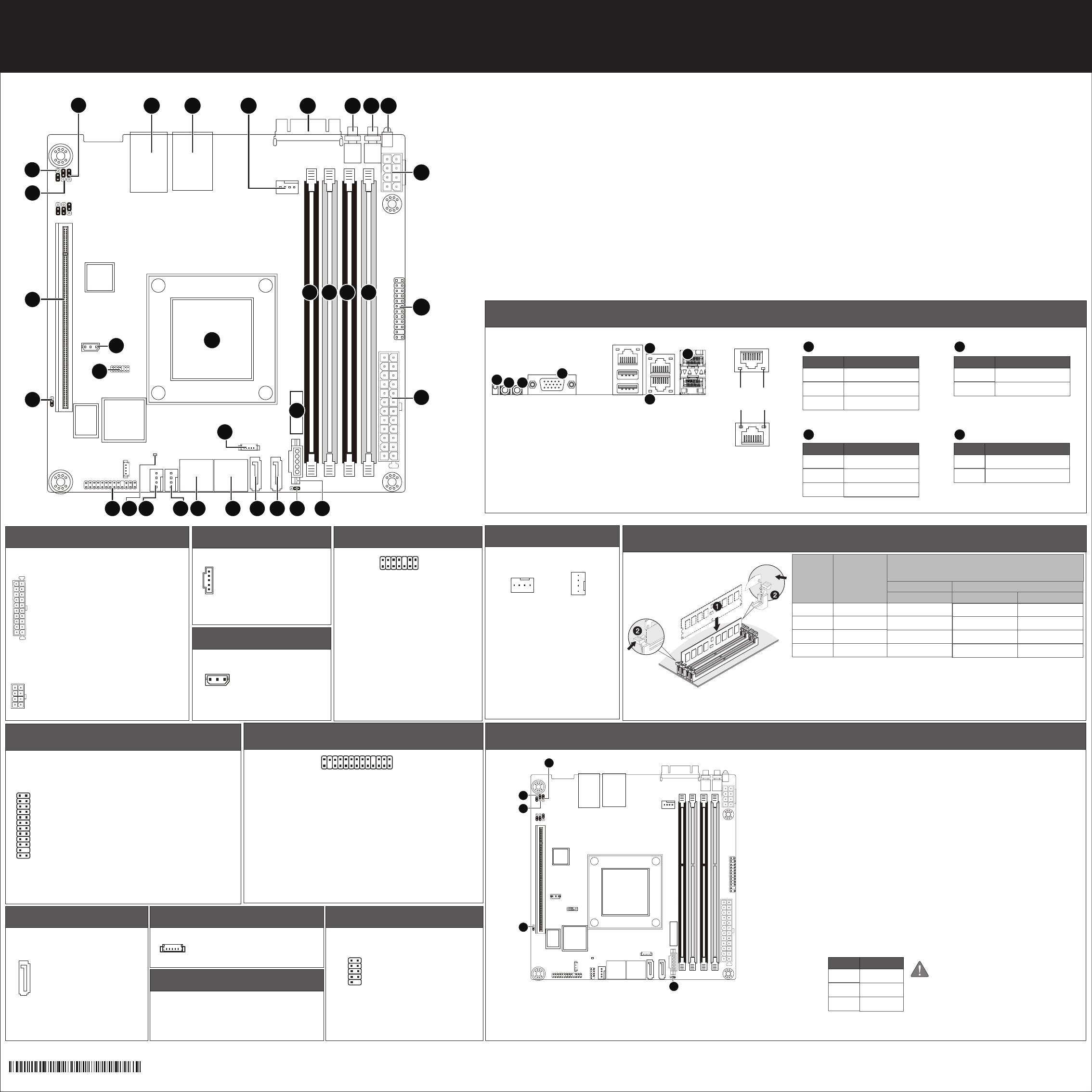
MB10-DS0/MB10-DS1 Quick Reference Guide/ 快速测试参考指南
1
5
13
1
84
51
24
1
12
23
1
225
26
No. Pin Define
1 3.3V
2 3.3V
3 GND
4 +5V
5 GND
6 +5V
7 GND
8 Power Good
9 5VSB
10 +12V
11 +12V
12 3.3V
No. Pin Define
1 GND
2 GND
3 GND
4 GND
No. Pin Define
1 PMBus Clock
2 PMBus Data
3 PMBus Alert
4 GND
5 3.3V Sense
No. Pin Define
1 Clock
2 GND
3 Data
No. Code Descripon
1 CPU Intel Xeon® processor D-1541, FCBGA1667 SoC (MB10-DS0)
Intel Xeon® processor D-1521, FCBGA1667 SoC (MB10-DS1)
2 LAN1_2 LAN ports
3 USB3_MLAN BMC Management LAN port (top) / USB 3.0 ports (boom)
4 CPU0_FAN CPU fan connector
5 VGA VGA port
6 SW_ID ID switch buon w/LED
7 SW_PWR Power buon w/LED
8 LED_STA System Status LED
9 P12V_AUX2 8 pin power connector
10 FP_1 Front panel header
11 ATX1 24 pin main power connector
12 DIMM_P0_A0 Channel 1 slot 0
13 DIMM_P0_A1 Channel 2 slot 1
14 DIMM_P0_B0 Channel 3 slot 0
15 DIMM_P0_B1 Channel 4 slot 1
16 BAT1 Baery
17 PMBUS PMBus connector
18 SATA_DOM0 SATA port 0 DOM support jumper
No. Pin Define
1 Power LED+
3 No Pin
5 Power LED-
7 HDD LED+
9 HDD LED-
11 Power Buon
13 GND
15 Reset Buon+
17 GND
19 ID Switch+
21 ID Switch-
23 NMI Switch-
No. Desripon
1 System Status LED
2 Power buon w/LED
3 ID switch buon w/LED
4 VGA port
5 USB 3.0 ports
6 KVM Server Management 10/100/1000 LAN Port (Dedicated LAN Port)
7 LAN ports
Note: DDR4 2400MHz is only available on Intel Xeon® D-1541 processor.
When only one DIMM is used, it must be populated in memory slot0 first.
System will not boot normally with incorrect populated sequence.
Speed LED
Power buon/LED:
Off
State Description
Yellow On 1Gbps data arte
Green On 100Mbps data arte
10Mbps data arte
710/100/1000 LAN LED:
Link/Acvity
LED
13
12
24
No. Code Descripon
19 SATA0 SATA 3 6Gb/s connector
20 SATA1 SATA 3 6Gb/s connector
21 SATA_2_3 SATA 3 6Gb/s connectors
22 SATA_4_5 SATA 3 6Gb/s connectors
23 SATA_SGPIO SATA SGPIO header
24 SYS_FAN2 System fan connector#2
25 SYS_FAN1 System fan connector#1
26 LED_BMC1 BMC firmware readiness LED
27 BP_1 HDD back plane board header
28 TPM TPM module connector
29 IPMB IPMB connector
30 CLR_CMOS Clear CMOS jumper
31 PCIE_1 PCI Express x16 slot
32 ME_UPDATE ME update jumper
33 ME_RCVR ME recovry jumper
34 S3_MASK S3 Power On Select jumper
Green On
Off
Description
System is powered on
System is powered off
State
ID switch buon w/LED:
Blue On
Off
Description
Unit selected for identification
No identification
State
System Status LED:
Green On
Amber On
Off
Description
Normal operation
Critical alert.
System is not ready
State
No. Pin Define
13 3.3V
14 -12V
15 GND
16 PS_ON
17 GND
18 GND
19 GND
20 -5V
21 +5V
22 +5V
23 +5V
24 GND
No. Pin Define
5 +12V
6 +12V
7 +12V
8 +12V
No. Pin Define
2 5V Standby
4 ID LED+
6 ID LED-
8 System Status LED+
10 System Status LED-
12 LAN1 Acve LED+
14 LAN1 Link LED-
16 SMBus Data
18 SMBus Clock
20 Case Open
22 LAN2 Acve LED
24 LAN2 Link LED-
No. Pin Define
1 BP_SGP_CLK
3 BP_SGP_GLD
5 BP_SGP_DOUT
7 Key Pin
9 GND
11 BP_LED_G_N
13 BP_SGP_DIN
15 GND
17 GND
19 P_3V3_AUX
21 P_3V3_AUX
23 GND
25 BP_PRESENSE
No. Pin Define
2 No Connect
4 FAN_SGP_GLD
6 GND
8 Reset
10 BP_LED_A_N
12 GND
14 No Connect
16 SMB_BP_DATA
18 SMB_BP_CLK
20 BMC_ACK
22 BMC_REQ
24 Key Pin
26 GND
No. Pin Define
1 GND
2 +12V
3 Sense
4 Speed Control
12QM1-MB10D0-00R
No. Pin Define
4 SLOAD
5 SCLK

