
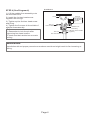
52"
CEILING FANS
Instruction Manual
SAFETY GUIDELINES AND INSTALLATION PROCEDURES
RCF-ONDULAR-3B
(
(SW720-301-BK)
(SW720-301-MB)
SW720-301-WH)
TBATBA

2
3
7
8
9
1
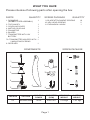
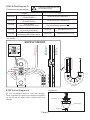
WHAT YOU HAVE
Please checkout following parts after opening the box
COMPONENTS
PARTS
QUANTITY
1. DOWNROD
(WOBBLE-FREE ASSEMBLY)
1
2. TOP CANOPY
1
5. FAN MOTOR
1
3. COUPLING COVER
7. TRANSMITTER WITH 12V
BATTERY
1
1
1
7A. TRANSMITTER HOLDER WITH
2 MOUNTING SCREWS
8. RECEIVER
1
Page 1
SCREW PACKAGE
5
1
FAN SIZE
VOLTAGE
MAX. FAN
POWER
MAX SPEED
(RPM)
SCREW PACKAGE
QUANTITY
9. BLADE ATTACHMENT SCREWS
11. EXPANSION J HOOK
10. HEX-HEAD SCREWS
1
10
2
11
10
4
4. MOTOR COUPLING
6. BLADES
3
1
PRODUCT
WEIGHT
CARTON
WEIGHT
6.20kgs
7.45 kgs
52”
200±10%
100W
220-240V/50Hz
6
7A

Page 2
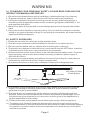
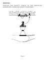
Double pole single throw switch(Breaker Switch)
Earth
Ceiling Fan
Wall Switch (OFF/ON)
8 ) This product is not provided with cord, plug or other means for disconnection from the
supply. Connecting or changing power cord or lead wire, must be done by qualified
personnel in order to avoid hazard.
9 ) This appliance is not intended for use by persons (including children) with reduced
physical, sensory or mental capabilities, or lack of experience and knowledge, unless
they have been given supervision or instruction concerning use of the appliance by a
person responsible for their safety.
10 ) Children should be supervised to ensure that they do not play with the appliance.
11 ) The appliance is fitted with means for disconnection from the supply mains having a
contact separation in all poles that provide full disconnection under overvoltage category
III conditions, and these means must be incorporated in the fixed wiring in accordance
with the wiring rules.
WARNING
A ). TO ENSURE YOUR PERSONAL SAFETY, PLEASE READ THROUGH THE
INSTRUCTION MANUAL BEFORE USE
1 ) Do not bend the blade holders during installation, blades balancing or fan cleaning.
2 ) To prevent accidents, power switch must be OFF before ceiling fan installation.
3 ) Ceiling fan installation and electrical wiring must be done by qualified technician in
accordance with all applicable codes and air conditioning engineers (ASHRAE) or the
local qualified authorities.
4 ) Be cautious when drilling the wall to avoid damaging electrical wiring and other hidden
parts.
5 ) Ceiling fan must be hooked on concrete ceiling. Do not install the ceiling fan on plaster
ceiling or any types of drywall ceilings. During ceiling fan installation, all screws must be
tightened at all allocated parts.
B ). SAFETY GUIDELINES
1 ) Please do not install the ceiling fan at high humidity areas.
2 ) The fan is to be installed so that the blades are more than 2,3 m above the floor.
3 ) Do not touch fan blades with any objects when the ceiling fan is spinning.
4 ) To minimize the chances of electrical shock, power switch must be OFF before installing
or dismantling the ceiling fan or any electrical wiring connection.
5 ) All electrical connections must conform to the national electrical safety codes. To prevent
electrical shock, earth wire must be installed correctly (suitable for power supply of
220-240V AC/50Hz).
6 ) To ensure your personal safety and optimize functions of the ceiling fan, assembly and
installation by qualified technician is highly recommended.
7 ) Only direct connection to wall switch is allowed. Please refer to diagram below.
220-240V AC/50Hz
Power Supply

INSTALLATION PROCEDURES
Page 3
STEP 2 (See Diagram 2)
1 ) Remove 1st hex-head screw along
with the fixings (pin, metal nut, lock
washer and metal washer) from the
downrod.
2 ) Remove the pin on 2nd hex-head
screw and loosen the other fixings.
DIAGRAM 2
The 1st Hex-head Screw
Pin
Metal Nut
Lock Washer
Metal Washer
The 2nd Hex-head Screw
Pin
Terminal Block
Fixings
STEP 3 (See Diagram 3)
1 ) Loosen 2 screws on the motor
coupling.
2 ) Insert the downrod through top canopy
and coupling cover.
3 ) Thread the safety cable through the
downrod.
4 ) Connect both connectors from the
downrod and fan motor.
5 ) Lock the downrod to the motor
coupling, tighten up with 2 hex-head
screws and fixings.
6 ) Tighten 2 screws on the motor
coupling.
7 ) Slide down the coupling cover until it
rest on top of the fan housing.
DIAGRAM 3
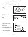
Before ceiling fan installation, please go through the procedures in
detail with picture diagrams as reference.
STEP 1 (See Diagram 1)
1 ) Align the 3 holes from the blade to the
fan motor.
2 ) Secure blade with 3 blade screws
provided. Follow the same process for
the remaining two blades.
DIAGRAM 1
Fan motor
Blade
Blade screw
Safety Cable
Connector
Top Canopy
Coupling Cover
Screw x 2
Hex-head Screw
Motor Coupling
Screw (Loosen)
Downrod

Page 4
STEP 4 (See Diagram 4)
1 ) Lift the wobble-free assembly onto
the mounted hook.
2 ) Install the 1st hex-head screw
together with fixings.
3 ) Tighten up the 2nd hex-head screw
and fixing.
4 ) Tighten the 2 screws in the middle of
wobble-free assembly.
Note:-
1. Remember to lock the pin after
tightening hex-head screws.
2. Hook must be installed on concrete
ceiling.
DIAGRAM 4
Wobble-free
Assembly
2 Screws in the middle
(Tighten)
Hook
The 1st
Hex-head Screw
The 2nd
Hex-head Screw
Metal Washer
Pin
Metal Nut
Lock Washer
Fixings
WARNING:
Installation without proper procedures as above mentioned might result to fan loosening or
falling.

Page 5
STEP 5 (See Diagram 5)
DIAGRAM 5
STEP 5 (See Diagram 5)
DIAGRAM 5
SUPPLY CIRCUIT
Receiver
EARTH wire
NEUTRAL wire
(Black / Blue )
LIVE wire
(Red / Brown)
L
N
L
N
L
N
Receiver
Ceiling
Ceiling
Ceiling
Receiver
Receiver
Receiver
Brown Wire
(TO MOTOR L)
Blue Wire
(TO MOTOR N)
Red / Brown Wire
(Incoming LIVE Wire)
Black / Blue Wire
(Incoming NEUTRAL Wire)
Green Wire
(Incoming EARTH Wire)
Red Wire (AC in L)
Black Wire (AC in N)
Terminal Block (marked )“L”
Terminal Block (marked )“N”
FROM TO
!
Connect the Motor Wiring
to Receiver first!
Connect wiring as below:-
Downrod
Receiver
Top Canopy
From Ceiling
From Ceiling
From Ceiling
Terminal Block (marked )“ ”
Fit the connected receiver into top canopy.
Then, tug the top canopy to ceiling and tighten
up the screw on down rod to secure the top
canopy.
Black
B
lu
e
Brow
n
Red
Green

WARNING!
FA S T EN T H E S AF E T Y C A B L E TO TH E M O U N T E D
EXPANSION J HOOK FOR SAFETY PURPOSES.
Page 6

GROUND
Page 7
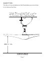
MIN 2 . 3 m
SAFETY TIPS:
The fan is to be installed so that the blades are more than
2,3 m above the floor.

RCF-ONDULAR-3B
(
(SW720-301-BK)
(SW720-301-MB)
SW720-301-WH)
52"
吊 扇
安 装 手 册
安全注意事项和安装程序
TBATBA

2
3
7
8
9
1
5
11
10
4
6
7A
1
2
1
10
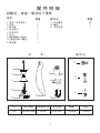
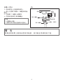
配 件 明 细
拆箱后,请逐一清点以下零件
零件
数量 数量
配件包
元 件 配 件 包
1. 吊杆(吊挂系统)
2. 吊盅
3. 接头盖
5. 风扇主体
1
1
1
1
1
1
1
7. 遥控器附12V电池
7A. 壁座附带2个螺丝
8. 接收器
9. 叶片螺丝
10. 螺栓
11. 安全挂钩
4. 马达接头
3
1
6. 叶片
6.20kgs 7.45kgs
52"
200±10%
100W
尺寸
电压/频率
风扇最大功率
最大转速
净重
毛重
220-240V/50Hz

2
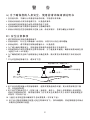
接地
吊扇
墙开关(关/开)
双柱单掷开关(断路开关)
警 告
A) 为了确保您的人身安全,使用前请详细阅读说明书
1. 在安装叶架,平衡叶片或清洁风扇的时候,不能将叶架弯曲。
2. 安装此吊扇前必须关闭电源开关,以免造成意外。
3. 此吊扇的安装和接电应由技术熟练的电工完成。
4. 注意钻墙的时候不要损坏电线和其它隐藏的零件。
5. 吊扇必须悬挂在坚定稳固的天花板上面,吊扇安装时,各部分螺丝必须锁牢。
8. 本产品没有提供插头或其他绝缘体,连接或更换电线的时候,建议请资深的技工操
作,以免造成危险。
9. 本产品不打算由这些人(包括儿童)来使用:身体上,感觉上或者精神上有缺陷者,
或缺乏经验和知识者。除非他们得到了在对其安全负责的人关于该项产品使用的监护
或指导(对所有产品)。
10. 儿童应当受到监督以确保其不会玩耍器具(对所有产品)
11. 本产品已配有双极断开装置(过电压等级III条下),按布线规则,其连接的固定布线必
须配有这样的断开装置。
B)安全注意事项
1. 请不要将吊扇安装在潮湿的地方。
2. 安装吊扇时,叶片至少离地面2.3米高处,以防与叶片发生意外碰触。
3. 吊扇运转时,请不要用任何物品碰触叶片,以免危险。
4. 为了减少触电事故发生,安装电线或拆装风扇前请及时关电源开关。
5. 所有的接电必须符合国家安全要求的标准,为了避免意外触电,确保吊扇接地线生效
(适用于220-240V供电)。
6. 为了确保您的安全和产品的使用达到最佳效果,建议要技术熟练的技工来安装此风
扇。
7. 只允许直接连接墙开关,请参考下图。
220-240V/50Hz供电

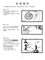
安 装 程 序
为了确保顺利安装此吊扇,请详细阅读以下步骤,并参照插图。
3
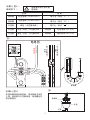
步骤1(图1)
1)用叶片上的三个螺丝与风扇马达上
相对应的螺丝孔一一对齐。
2)用螺丝包的叶片螺丝将叶片锁紧在
风扇马达上。
图1
步骤2(图2)
1)把吊杆上第一个螺栓和其他配件一
起拆下(R销,螺母,弹介和平华
司)。
2)把第二个螺栓上的R销拆下,松开
其他配件。
步骤3(图3)
1)松开马达接头上的2颗预锁螺丝。
2)将吊杆穿入吊盅和接头盖。
3)将安全钢索穿过吊杆。
4)把马达上的接线套接到吊杆的接线
套上。
5)将吊杆套入马达接头处,对准孔,
用配件包里的螺栓锁上。
6)锁紧之前松开的螺丝。
7)把接头盖移至马达的上端。
图2
图3
吊盅
接头盖
安全钢索
马达接头
螺栓
接线套
R销
螺母
弹介
平华司
R销
第2个螺栓
端子台
第1个螺栓
配件
螺丝(松开)
吊管
螺丝x2
风扇马达
叶片
叶片螺丝

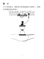
步骤4(图4)
1)将吊扇挂上已装紧的吊钩上。
3)拧紧第二个螺栓上的配件。
4)拧紧吊挂系统上的2颗螺丝。
2)装上之前拆下的第一个螺栓和其他
配件。
图4
注意:-
1. 记得插上R销。
2. 吊钩必须安装在坚固的天花板上。
如 果 没 有 按 照 上 面 指 示 把 吊 杆 装 紧 , 有 可 能 会 导 致 吊 扇 下 坠 。
警 告
吊钩
第2个螺栓
第1个螺栓
R销
螺母
弹介
平华司
吊挂系统
螺丝(锁紧)
配件
4

步骤6(图6)
吊盅
图6
图5
步骤5(图5):
红色 / 棕色(天花板火线)
天花板
天花板
天花板
端子台(标注“L”)
蓝色电线 (TO MOTOR N)
棕色电线 (TO MOTOR L)
绿色(天花板地线)
黑色 / 蓝色(天花板零线)
接收器
接收器
接收器
接收器
黑色电线 (AC in N)
红色电线 (AC in L)
端子台(标注“N”)
接 线
出 线
接收器
吊杆
把接收器放进吊钟里面,
上端,使吊钟与天花板贴紧,锁紧螺丝并
把吊钟固定。
把吊钟移至吊杆
L
N
L
N
L
N
接地线
(黑 / 蓝色电线)
零线
(红 / 棕色电线)
火线
电路图
接收器
!
接收器必须先与风扇
接好线
接线如下:-
From Ceiling
From Ceiling
From Ceiling
端子台(标注“ ”)
5
黑色
蓝色
棕色
红色
绿色

警 示
为了安全起见,请把安全吊钩装紧在天花板上,再把
安全钢丝挂在吊钩上。
6

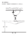
最少2.3米
安 全 提 示 :
地 面
7
安全起见,请确保叶片距离地面至少2.3米或以上。
-
 1
1
-
 2
2
-
 3
3
-
 4
4
-
 5
5
-
 6
6
-
 7
7
-
 8
8
-
 9
9
-
 10
10
-
 11
11
-
 12
12
-
 13
13
-
 14
14
-
 15
15
-
 16
16


