
© 2003 Sony Corporation Printed in Japan
DVX-11A
3-255-986-21 (1)
Installation/Connections
Mobile DVD
Player
Foot brake type
Hand brake type
Parking brake switch cord
4
Using the tap
c
Connection box
Front speaker (Left)
Rear speaker (Left)
Subwoofer
Media center main unit
Front speaker (Right)
Rear speaker (Right)
Headrest Monitor
Overhead monitor
Sony DVD player DVX-11A
2
Parking cord (Light green) of 2
2
Parking brake switch cord
Parking brake switch cord
3
Cautions
•This unit is designed for negative ground 12 V
DC operation only.
•Do not pinch wires under screws, or in moving
parts (e.g., seat railing).
•Before making connections, turn the car
ignition off to avoid short circuits.
•Connect the yellow and red power input leads
only after all other leads have been connected.
•Run all ground wires to a common ground
point.
•Be sure to insulate any loose unconnected
wires with electrical tape for safety.
•The use of optical instruments with this
product will increase the risk of eye injury.
•Control adjustments and procedures other
than those specified herein may result in
hazardous radiation exposure.
•For your safety, the monitor connected to the
FRONT VIDEO OUT can only be viewed when
the car is stopped and the parking brake
applied.
Be sure to connect the parking cord (Light
green) of 2 to the car’s parking brake switch
cord.
Notes on the power supply cord (yellow)
•When connecting this unit in combination with
other stereo components, the connected car
circuit’s rating must be higher than the sum of
each component’s fuse.
•When no car circuits are rated high enough,
connect the unit directly to the battery.
Parts Iist (1)
The numbers in the list are keyed to those in the
instructions.
Installation diagram (2)
Example:
Dashboard installation.
Note
All the equipment other than the Sony DVD player
DVX-11A and the remote control sensor is not
supplied.
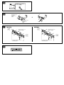
Connecting the parking brake
cord (3)
Be sure to connect the parking cord (Light
green) of 2 to the parking brake switch cord.
The mounting position of the parking brake
switch cord depends on your car. Consult your
car dealer or your nearest Sony dealer for
further details.
Using the tap
Attach the tap 4 to the end of the parking cord
(Light green) of 2 and the parking brake switch
cord.
Note
If the parking brake switch cord is too thin, connect
the parking cord (Light green) of 2 to the parking
brake switch cord directly without using the tap 4.
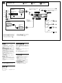
Connection diagram (4)
1 To a metal surface of the car
First connect the black ground lead, then
connect the yellow and red power input leads.
2 To the +12 V power terminal which is energized
in the accessory position of the ignition key
switch
Note
If there is no accessory position, connect to the
+12 V power (battery) terminal which is
energized at all times.
Be sure to connect the black ground lead to a
metal surface of the car first.
3 To the +12 V power terminal which is energized
at all times
Be sure to connect the black ground lead to a
metal surface of the car first.
4 To the parking brake switch cord
5 To a digital amplifier or audio device
Connect the optical cable RC-97/98 (not
supplied), etc., to a digital amplifier or audio
device equipped with a Dolby digital decoder.
1
× 4
56
32
4
3PM3 × 6
3T5 × 8
1

•
•
•
•
•
•
•
•
•
2
•
•
1
2
FRONT
REAR
R
AUDIO OUT
DIGITAL OUT
REMOTE
SIGNAL
IN
VIDEO
OUT
L
DIGITAL OUT
FRONT AUDIO/
VIDEO OUT
REAR AUDIO/
VIDEO OUT
Connection box
Optical adapter XA-D211 (not supplied)*
1
*
1
Optical cable RC-97/98 (not supplied)*
1
*
1
3
2
Black
Red
Yellow
Fuse (5 A)
Light green
Headrest Monitor
Media center main unit
Left
Left
Right
Right
5 m
0.45 m
0.25 m
0.25 m
2.5 m
Rear monitor system
Equipment used in illustrations (not supplied)
Front speaker
Rear speaker
Subwoofer
Front monitor system
*
1
For details on connecting the optical cable and
the optical adapter, see the “When making a
digital connection (6)” on the reverse side.
*
2
For details on connecting to the parking brake
switch cord, and attaching the tap 4, see
“Connecting the parking brake cord (3).”
*
6
* 4
3
4
4*
2
Connection box
RCA pin cord
(not supplied)
3
2
4 2
2
4
4
1
2
3
4
5

Optical cable RC-97/98
(not supplied)
Optical adapter XA-D211
(not supplied)
c
5
6
6
5
NTSC
PA L
PAL/NTSC select switch
NISSAN
7 TOYOTA
to dashboard/center console
to dashboard/center console
Bracket
Bracket
Bracket
Existing parts supplied with your car
Existing parts supplied with your car
max. size
5 × 8 mm
×
1
1
1
Bracket
max. size
5 × 8 mm
×
1
8
max. size
5 × 8 mm
×
max. size
5 × 8 mm
×

Precautions
•Choose the installation location carefully so
that the unit will not interfere with normal
driving operations.
•Avoid installing the unit in areas subject to
dust, dirt, excessive vibration, or high
temperatures, such as in direct sunlight or near
heater ducts.
•Use only the supplied mounting hardware for
a safe and secure installation.
Mounting angle adjustment
Adjust the mounting angle to less than 20°.
PAL/NTSC select switch (5)
Before installing the unit, set the PAL/NTSC
select switch on the bottom of the unit to “PAL”
or “NTSC” according to the color system of your
country.
When making a digital
connection (6)
When connecting to a digital amplifier or audio
device equipped with a Dolby digital decoder,
connect the optical cable to the optical adaptor
first, then connect the optical adapter to the
DIGITAL OUT on the back panel.
Notes
•When you wish to disconnect the optical cable,
simply push in on both sides of the connector.
• Be sure to keep the protective cap in a safe place
for future use.
• Do not bend the optical cable too much. If it is
bent in an arc of less than 10 cm in diameter,
sound may not be reproduced.
• Be sure to use an optical cable (not supplied) and
an optical adapter (not supplied) designed for
Sony car audio systems.
• Make sure that the optical cable is securely
plunged to the optical adapter when making
connection.
• Make sure the optical cable does not get
compressed or constricted in any way by
surrounding objects.
• Never let the coupler parts of the connectors get
scratched or become contaminated with dirt.
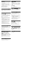
Mounting example (7)
Installation in a Japanese car
You may not be able to install this unit in some
makes of Japanese cars. In such a case, consult
your Sony dealer.
Note
To prevent malfunction, install only with the
supplied screws 1.
Warning when installing in a car
without ACC (accessory)
position on the ignition key
switch
Be sure to press and hold (OFF) on the unit
until the key illuminations in blue go off after
turning off the engine.
When you press (OFF) only momentarily, the
unit does not turn off and this causes battery
wear.
Reset button (8)
When the installation and connections are
completed, be sure to press the reset button with
a ballpoint pen, etc., to reset the unit.
•
•
•
5
6
•
•
•
•
•
•
•
7
1
(OFF)
(OFF)
8
-
 1
1
-
 2
2
-
 3
3
-
 4
4


