
1
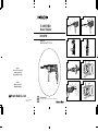
Read through carefully and understand these instructions before use.
Rotary Hammer
HANDLING INSTRUCTIONS
DH 24PB3
1
2
4
6
8
3
5
7
Hitachi Koki Co., Ltd.
812
Code No. C99139823 F
Printed in China
1
2
3
4
4
5
6
服務中心
日立工機商業(中國)有限公司
上海市長寧區遵義路100號
虹橋上海城B棟2686-2689室
秶婖妀
制造商
福建日立工機有限公司
福建省福州市福興投資區

1
Read through carefully and understand these instructions before use.
Rotary Hammer
HANDLING INSTRUCTIONS
DH 24PB3
1
2
4
6
8
3
5
7
Hitachi Koki Co., Ltd.
812
Code No. C99139823 F
Printed in China
1
2
3
4
4
5
6
服務中心
日立工機商業(中國)有限公司
上海市長寧區遵義路100號
虹橋上海城B棟2686-2689室
秶婖妀
制造商
福建日立工機有限公司
福建省福州市福興投資區

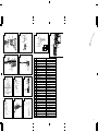
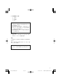
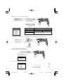
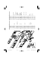
Drill bit
Part of SDS-plus shank
Front cap
Grip
Dust cup
Dust collector (B)
Push button
Change lever
Push button
Drill chuck
Chuck adapter
Chuck adapter (D)
Driver bit
Socket
Side handle
Depth gauge
Mounting hole
Tape shank adapter
Cotter
Rest
Core bit
Core bit shank
Thread
Center pin
Guide plate
Core bit tip
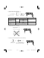
Wear limit
No. of carbon brush
Usual carbon brush
Auto-stop carbon brush
Brush holder
Carbon brush
Internal wiring
Switch
3
2
24
1
2
3
4
5
6
7
8
9
0
A
B
C
D
E
F
G
H
I
J
K
L
M
N
O
P
Q
R
S
T
U
V
W
X
9
10
13
16
14 15
C
D
B
H
J
K
L
M
O
N
K
P
12
11
1
H
I
17 18
L
3
4
4
3
2
A
0
3
4
F
G
19
a R
S 5mm 41
T –72
a
12 mm
R
Q
20
E
W
V
X
U

Drill bit
Part of SDS-plus shank
Front cap
Grip
Dust cup
Dust collector (B)
Push button
Change lever
Push button
Drill chuck
Chuck adapter
Chuck adapter (D)
Driver bit
Socket
Side handle
Depth gauge
Mounting hole
Tape shank adapter
Cotter
Rest
Core bit
Core bit shank
Thread
Center pin
Guide plate
Core bit tip
Wear limit
No. of carbon brush
Usual carbon brush
Auto-stop carbon brush
Brush holder
Carbon brush
Internal wiring
Switch
3
2
24
1
2
3
4
5
6
7
8
9
0
A
B
C
D
E
F
G
H
I
J
K
L
M
N
O
P
Q
R
S
T
U
V
W
X
9
10
13
16
14 15
C
D
B
H
J
K
L
M
O
N
K
P
12
11
1
H
I
17 18
L
3
4
4
3
2
A
0
3
4
F
G
19
a R
S 5mm 41
T –72
a
12 mm
R
Q
20
E
W
V
X
U

4
08.10.31, 15:32Page 4

5
嘷
08.10.31, 15:32Page 5

6
嘷
嘷
嘷
嘷
08.10.31, 15:32Page 6

7
嘷
08.10.31, 15:32Page 7

8
嘷
嘷
08.10.31, 15:32Page 8

9
嘷
嘷
嘷
嘷
嘷
嘷
嘷
嘷
嘷
嘷
嘷
嘷
08.10.31, 15:32Page 9

10
嘷
嘷
嘷
嘷
嘷
08.10.31, 15:32Page 10

11
08.10.31, 15:32Page 11

12
08.10.31, 15:32Page 12

13
GENERAL SAFETY RULES
WARNING!
Read all instructions
Failure to follow all instructions listed below may result in
electric shock, fire and/or serious injury.
The term “power tool” in all of the warnings listed below
refers to your mains operated (corded) power tool or
battery operated (cordless) power tool.
SAVE THESE INSTRUCTIONS
1) Work area
a) Keep work area clean and well lit.
Cluttered and dark areas invite accidents.
b) Do not operate power tools in explosive
atmospheres, such as in the presence of flammable
liquids, gases or dust.
Power tools create sparks which may ignite the
dust of fumes.
c) Keep children and bystanders away while
operating a power tool.
Distractions can cause you to lose control.
2) Electrical safety
a) Power tool plugs must match the outlet.
Never modify the plug in any way.
Do not use any adapter plugs with earthed
(grounded) power tools.
Unmodified plugs and matching outlets will
reduce risk of electric shock.
b) Avoid body contact with earthed or grounded
surfaces such as pipes, radiators, ranges and
refrigerators.
There is an increased risk of electric shock if
your body is earthed or grounded.
c) Do not expose power tools to rain or wet conditions.
Water entering a power tool will increase the
risk of electric shock.
d) Do not abuse the cord. Never use the cord for
carrying, pulling or unplugging the power tool.
Keep cord away from heat, oil, sharp edges or
moving parts.
Damaged or entangled cords increase the risk
of electric shock.
e) When operating a power tool outdoors, use an
extension cord suitable for outdoor use.
Use of a cord suitable for outdoor use reduces
the risk of electric shock
3) Personal safety
a) Stay alert, watch what you are doing and use
common sense when operating a power tool.
Do not use a power tool while you are tired or
under the influence of drugs, alcohol or medication.
A moment of inattention while operating power
tools may result in serious personal injury.
b) Use safety equipment. Always wear eye
protection.
Safety equipment such as dust mask, non-skid safety
shoes, hard hat, or hearing protection used for
appropriate conditions will reduce personal injuries.
c) Avoid accidental starting. Ensure the switch is in
the off position before plugging in.
Carrying power tools with your finger on the
switch or plugging in power tools that have the
switch on invites accidents.
d) Remove any adjusting key or wrench before
turning the power tool on.
A wrench or a key left attached to a rotating part
of the power tool may result in personal injury.
e) Do not overreach. Keep proper footing and balance
at all times.
This enables better control of the power tool in
unexpected situations.
f) Dress properly. Do not wear loose clothing or
jewellery. Keep your hair, clothing and gloves
away from moving parts.
Loose clothes, jewellery or long hair can be
caught in moving parts.
g) If devices are provided for the connection of dust
extraction and collection facilities, ensure these
are connected and properly used.
Use of these devices can reduce dust related hazards.
4) Power tool use and care
a) Do not force the power tool. Use the correct
power tool for your application.
The correct power tool will do the job better and
safer at the rate for which it was designed.
b) Do not use the power tool if the switch does not
turn it on and off.
Any power tool that cannot be controlled with
the switch is dangerous and must be repaired.
c) Disconnect the plug from the power source before
making any adjustments, changing accessories,
or storing power tools.
Such preventive safety measures reduce the risk
of starting the power tool accidentally.
d) Store idle power tools out of the reach of children
and do not allow persons unfamiliar with the
power tool or these instructions to operate the
power tool.
Power tools are dangerous in the hands of
untrained users.
e) Maintain power tools. Check for misalignment or
binding of moving parts, breakage of parts and
any other condition that may affect the power
tools operation.
If damaged, have the power tool repaired before
use.
Many accidents are caused by poorly maintained
power tools.
f) Keep cutting tools sharp and clean.
Properly maintained cutting tools with sharp cutting
edges are less likely to bind and are easier to control.
g) Use the power tool, accessories and tool bits etc.,
in accordance with these instructions and in the
manner intended for the particular type of power
tool, taking into account the working conditions
and the work to be performed.
Use of the power tool for operations different from
intended could result in a hazardous situation.
5) Service
a) Have your power tool serviced by a qualified repair
person using only identical replacement parts.
This will ensure that the safety of the power tool
is maintained.
PRECAUTION
Keep children and infirm persons away.
When not in use, tools should be stored out of reach of
children and infirm persons.
08.11.4, 18:02Page 13

14
PRECAUTIONS ON USING ROTARY HAMMER
1. Wear ear protections
Exposure to noise can cause hearing loss.
2. Do not touch the bit during or immediately after
operation. The bit becomes very hot during operation
and could cause serious burns.
3. Before starting to break, chip or drill into a wall,
floor or ceiling, thoroughly confirm that such items
as electric cables or conduits are not buried inside.
4. Use auxiliary handles supplied with the tool.
Loss of control can cause personal injury.
5. Always hold the body handle and side handle of
the power tool firmly. Otherwise the counterforce
produced may result in inaccurate and even
dangerous operation.
6. Wear a dust mask
Do not inhale the harmful dusts generated in drilling
or chiseling operation. The dust can endanger the
health of yourself and bystanders.
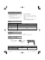
SPECIFICATIONS
Voltage (by areas)* (110V, 115V, 120V, 127V, 220V, 230V, 240V)
Power Input 800 W*
No-load speed
0 – 1050 / min.
Full-load impact rate
0 – 4600 / min.
Capacity: concrete 3.4 – 24 mm
steel 13 mm
wood 32 mm
Weight (without cord and side handle) 2.3 kg
*Be sure to check the nameplate on product as it is subject to change by areas.
STANDARD ACCESSORIES
(1) Plastic case .................................................................. 1
(2) Side handle ................................................................. 1
(3) Depth gauge ............................................................... 1
Standard accessories are subject to change without
notice.
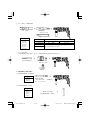
OPTIONAL ACCESSORIES (sold separately)
1. Drilling anchor holes (rotation + hammering)
䡬 Drill bit (Slender shaft)
Drill bit (slender shaft)
Outer diameter Effective length Overall length
3.4 mm
45 mm 90 mm
3.5 mm
Adapter for slender shaft
(SDS-plus shank)
Drill bit (Slender shaft)
08.11.4, 18:02Page 14

15
Drill bit (Taper shank)
Taper shank adapter
(SDS-plus shank)
Cotter
Outer diameter
11.0 mm
12.3 mm
12.7 mm
14.3 mm
14.5 mm
17.5 mm
21.5 mm
Taper mode Applicable drill bit
Morse taper (No.1) Drill bit (taper shank) 11.0 ~ 17.5 mm
Morse taper (No.2) Drill bit (taper shank) 21.5 mm
A-taper Taper shank adapter formed A-taper or B-taper
is provided as an optional accessory, but the
B-taper
drill bit for it is not provided.
䡬 Drill bit (Taper shank) and taper shank adapter
( )
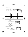
Straight shank bit
for impact drill
䡬 13 mm Hammer drill chuck
For drilling operations when using a straight shank bit for impact drilling with a rotary hammer.
13 mm Hammer drill chuck
(SDS-plus shank)
Chuck wrench
䡬 Anchor setting adapter (for manual hammer)
Anchor setting adapter
(for manual Hammer)
Anchor setting adapter (SDS-plus shank)
(for rotary hammer)
Overall length: 160, 260 mm
Anchor size
W1/4”
W5/16”
W3/8”
Anchor size
W1/4”
W5/16”
W3/8”
W1/2”
W5/8”
2. Anchor setting (rotation + hammering)
䡬 Anchor setting adapter (for rotary hammer)
08.11.4, 18:02Page 15

16
3. Large hole boring (rotation + hammering)
䡬 Center pin, core bit, core bit shank and guide plate.
(Guide plate) Center pin Core bit Core bit shank
(SDS-plus shank)
Center pin Core bit (outer diameter) Core bit shank
–
25 mm
29 mm
(A)
32 mm Core bit shank (A)
Center pin (A) 35 mm
38 mm
45 mm
Center pin (B) (B)
50 mm
Core bit shank (B)
Do not use core bits with with guide plate
outer diameter of 25 mm (The guide plate is not equipped with core bits
and 29 mm. with outer diameter of 25 mm and 29 mm.)
4. Crushing operation (rotation + hammering)
Bull point (Round type only)
(SDS-plus shank)
5. Bolt placing operation with Chemical Anchor (rotation + hammering)
(SDS-plus shank)
12.7 mm Chemical Anchor Adapter
19 mm Chemical Anchor Adapter
Standard socket
on the market
( )
08.11.4, 18:03Page 16

17
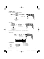
6. Drilling holes and driving screws (rotation only)
䡬 Drill chuck, chuck adapter (G), special screw and chuck wrench
Chuck adapter (G)
(SDS-plus shank)
Chuck wrench
Drill chuck (13VLRB-D)Special screw
7. Drilling holes (rotation only)
Chuck adapter (D)
(SDS Plus shank)
Chuck wrench
䡬 13 mm drill chuck ass’y (includes chuck wrench) and chuck (for drilling in steel or wood).
8. Driving Screws (rotation only)
Chuck adapter (D)
(SDS-plus shank)
Bit No. Screw Size Length
No. 2 3 – 5 mm 25 mm
No. 3 6 – 8 mm 25 mm
Bit No.
Drill chuck (13VLD-D)
9. Dust cup, Dust collector (B)
Optional accessories are subject to change without notice.
Dust cup
Dust collector (B)
10. Hammer grease A
500 g (in a can)
70 g (in a green tube)
30 g (in a green tube)
08.11.4, 18:03Page 17

18
APPLICATIONS
Rotation and hammering function
䡬 Drilling anchor holes
䡬 Drilling holes in concrete
䡬 Drilling holes in tile
Rotation only function
䡬 Drilling in steel or wood
(with optional accessories)
䡬 Tightening machine screws, wood screws
(with optional accessories)
PRIOR TO OPERATION
1. Power source
Ensure that the power source to be utilized conforms
to the power requirements specified on the product
nameplate.
2. Power switch
Ensure that the power switch is in the OFF position. If
the plug is connected to a receptacle while the power
switch is in the ON position, the power tool will start
operating immediately, which could cause a serious
accident.
3. Extension cord
When the work area is removed from the power
source, use an extension cord of sufficient thickness
and rated capacity. The extension cord should be kept
as short as practicable.
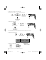
4. Mounting the drill bit (Fig. 1)
CAUTION
To prevent accidents, make sure to turn the switch off
and disconnect te plug from the receptacle.
NOTE
When using tools such as bull points, drill bits, etc.,
make sure to use the genuine parts designates by our
company.
(1) Clean the shank portion of the drill bit.
(2) Insert the drill bit in a twisting manner into the tool
holder until it latches itself (Fig. 1).
(3) Check the latching by pulling on the drill bit.
(4) To remove the drill bit, fully pull the grip in the
direction of the arrow and pull out the drill bit (Fig. 2).
5. Installation of dust cup or dust collector (B)
(Optional accessories) (Fig. 3, Fig. 4)
When using a rotary hammer or upward drilling
operations attach a dust cup or dust collector (B) to
collect dust or particles for easy operation.
䡬 Installing the dust cup
Use the dust cup by attaching to the drill bit as shown
in Fig. 3.
When using a bit which has big diameter, enlarge the
center hole of the dust cup with this rotary hammer.
䡬 Installing dust collector (B)
When using dust collector (B), insert dust collector (B)
from the tip of the bit by aligning it to the groove on the
grip (Fig. 4).
CAUTION
䡬 The dust cup and dust collector (B) are for exclusive
use of concrete drilling work. Do not use them for
wood or metal drilling work.
䡬 Insert dust collector (B) completely into the chuck part
of the main unit.
䡬 When turning the rotary hammer on while dust
collector (B) is detached from a concrete surface, dust
collector (B) will rotate together with the drill bit. Make
sure to turn on the switch after pressing the dust cup
on the concrete surface. (When using dust collector
(B) attached to a drill bit that has more than 190 mm of
overall length, dust collector (B) cannot touch the
concrete surface and will rotate. Therefore please use
dust collector (B) by attaching to drill bits which have
166 mm, 160 mm, and 110 mm overall length.)
䡬 Dump particles after every two or three holes when
drilling.
䡬 Please replace the drill bit after removing dust collector
(B).
6. Selecting the driver bit
Screw heads or bits will be damaged unless a bit
appropriate for the screw diameter is employed to
drive in the screws.
7. Confirm the direction of bit rotation (Fig. 5)
The bit rotates clociwise (viewed from the rear side) by
pushing the R-side of the push button. The L-side of
the push button is pushed to turn the bit
counterclockwise.
HOW TO USE
CAUTION
To prevent accidents, make sure to turn the switch off and
disconnect the plug from the receptacle when the drill pits
and other various parts are installed or removed. The
power switch should also be turned off during a work
break and after work.
1. Switch operation
The rotation speed of the drill bit can be controlled
steplessly by varying the amount that the trigger
switch is pulled. Speed is low when the trigger switch
is pulled slightly and increases as the switch is pulled
more. Continuous operation may be attained by
pulling the trigger switch and depressing the stopper.
To turn the switch OFF, pull the trigger switch again
to disengage the stopper, and release the trigger
switch to its original position.
However, the switch trigger can only be pulled in
halfway during reverse and rotates at half the speed of
forward operation.
The switch stopper is unusable during reverse.
2. Rotation + hammering
This rotary hammer can be set to rotation and
hammering mode by pressing the push button and
turning the change lever to the
mark (Fig. 6).
(1) Mount the drill bit.
(2) Pull the trigger switch after applying the drill bit tip to
the drilling position (Fig. 7).
(3) Pushing the rotary hammer forcibly is not necessary
at all. Pushing slightly so that drill dust comes out
gradually is sufficient.
CAUTION
When the drill bit touches construction iron bar, the bit
will stop immediately and the rotary hammer will
react to revolve. Therefore grip the side handle and
handle tightly as shown in Fig. 7.
3. Rotation only
This rotary hammer can be set to rotation only mode
by pressing the push button and turning the change
lever to the
mark (Fig. 8).
To drill wood or metal material using the drill chuck
and chuck adapter (optional accessories), proceed as
follows.
Installing drill chuck and chuck adapter (Fig. 9).
08.11.4, 18:03Page 18

19
(1) Attach the drill chuck to the chuck adapter.
(2) The part of the SDS-plus shank is the same as the drill
bit. Therefore, refer to the item of “Mounting the drill
bit” for attaching it.
CAUTION
䡬 Application of force more than necessary will not only
expedite the work, but will deteriorate the tip edge of
the drill bit and reduce the service life of the rotary
hammer in addition.
䡬 Drill bits may snap off while withdrawing the rotary
hammer from the drilled hole. For withdrawing, it is
important to use a pushing motion.
䡬 Do not attempt to drill anchor holes or holes in concrete
with the machine set in the rotation only function.
䡬 Do not attempt to use the rotary hammer in the
rotation and striking function with the drill chuck and
chuck adapter attached. This would seriously shorten
the service life of every component of the machine.
4. When driving machine screws (Fig. 10)
First, insert the bit into the socket in the end of chuck
adapter (D).
Next, mount chuck adapter (D) on the main unit using
procedures described in 4 (1), (2), (3), put the tip of the
bit in the slots in the head of the screw, grasp the main
unit and tighten the screw.
CAUTION
䡬 Exercise care not to excessively prolong driving time,
otherwise, the screws may be damaged by excessive
force.
䡬 Apply the rotary hammer perpendicularly to the screw
head when driving the screw; otherwise, the screw
head or bit will be damaged, or driving force will not
be fully transferred to the screw.
䡬 Do not attempt to use the rotary hammer in the
rotation and striking function with the chuck adapter
and bit attached.
5. When driving wood screws (Fig. 10)
(1) Selecting a suitable driver bit
Employ plus-head screws, if possible, since the driver
bit easily slips off the heads of minus-head screws.
(2) Driving in wood screws
䡬 Prior to driving in wood screws, make pilot holes
suitable for them in the wooden board. Apply the bit
to the screw head grooves and gently drive the screws
into the holes.
䡬 After rotating the rotary hammer at low speed for a
while until the wood screw is partly driven into the
wood, squeeze the trigger more strongly to obtain the
optimum driving force.
CAUTION
Exercise care in preparing a pilot hole suitable for the
wood screw taking the hardness of the wood into
consideration. Should the hole be excessively small
or shallow, requiring much power to drive the screw
into it, the thread of the wood screw may sometimes
be damaged.
6. Using depth gauge (Fig. 11)
(1) Loosen the knob on the side handle, and insert the
depth gauge into the mounting hole on the side
handle.
(2) Adjust the depth gauge position according to the
depth of the hole and thighten the knob securely.
7. How to use the drill bit (taper shank) and the taper
shank adapter
(1) Mount the taper shank adapter to the rotary hammer
(Fig. 12).
(2) Mount the drill bit (taper shank) to the taper shank
adapter (Fig. 12).
(3) Turn the switch ON, and drill a hole in prescribed
depth.
(4) To remove the drill bit (taper shank), insert the cotter
into the slot of the taper shank adapter and strike the
head of the cotter with a hammer supporting on a
rests (Fig. 13).
HOW TO USE THE CORE BIT
(FOR LIGHT LOAD)
When boring penerating large holes use the core bit (for
light loads). At that time use with the center pin and the
core bit shank provided as optional accessories.
1. Mounting
CAUTION
Be sure to turn power OFF and disconnect the plug
from the receptacle.
(1) Mount the core bit to the core bit shank (Fig. 14).
Lubricate the thread of the core bit shank to facilitate
disassembly.
(2) Mount the core bit to the rotary hammer (Fig. 15).
(3) Insert the center pin into the guide plate until it stops.
(4) Engage the guide plate with the core bit, and turn the
guide plate to the left or the right so that it does not fall
even if it faces downward (Fig. 16).
2. How to bore (Fig. 17)
(1) Connect the plug to the power source.
(2) A spring is installed in the center pin.
Push it lightly to the wall or the floor straight.
Connect the core bit tip flush to the surface and start
operating.
(3) When boring about 5 mm in depth the position of the
hole will be established. Bore after that removing the
center pin and the guide plate from core bit.
(4) Application of excessive force will not only expedite
the work, but will deteriorate the tip edge of the drill
bit, resulting in reduced service life of the rotary
hammer.
CAUTION
When removing the center pin and the guide plate,
turn OFF the switch and disconnect the plug from the
receptacle.
3. Dismounting (Fig. 18)
Remove the core bit shank from the rotary hammer
and strike the head of the core bit shank strongly two
or three times with a hammer holding the core bit,
then the thread becomes loose and the core bit can be
removed.
LUBRICATION
Low viscosity grease is applied to this rotary hammer so
that it can be used for a long period without replacing the
grease. Please contact the nearest service center for
grease replacement when any grease is leaking form
loosened screw.
Further use of the rotary hammer with lock off grease will
cause the machine to seize up reduce the service life.
CAUTION
A special grease is used with this machine, therefore,
the normal performance of the machine may be badly
affected by use of other grease. Please be sure to let
one of our service agents undertake replacement of
the grease.
08.11.4, 18:03Page 19
ページが読み込まれています...
ページが読み込まれています...
ページが読み込まれています...
ページが読み込まれています...
ページが読み込まれています...
ページが読み込まれています...
-
 1
1
-
 2
2
-
 3
3
-
 4
4
-
 5
5
-
 6
6
-
 7
7
-
 8
8
-
 9
9
-
 10
10
-
 11
11
-
 12
12
-
 13
13
-
 14
14
-
 15
15
-
 16
16
-
 17
17
-
 18
18
-
 19
19
-
 20
20
-
 21
21
-
 22
22
-
 23
23
-
 24
24
-
 25
25
-
 26
26


他の言語で
- English: Hikoki DH24PB3 User manual
関連論文
その他のドキュメント
-
Makita HR2470 ユーザーマニュアル
-
Hitachi D 6SH Handling Instructions Manual
-
-
Makita HR2652 ユーザーマニュアル
-
-
Infocus W 6VM ユーザーマニュアル
-
-
-
-
Stanley SHR243K ユーザーマニュアル