Shure SCM262 は、マイクロホンと一般家庭用のステレオ製品を統合する音響補強用途向けのステレオミキサーです。3つのアンバランス・ステレオ補助レベル入力付きの2つのアクティブバランス・マイクロホン入力を備えています。
レストラン、教室、企業研修、エアロビクスクラスなど、ページング/場内放送システムがバックグラウンドミュージックやその他のプログラム素材と組み合わされる状況向けに設計されています。
主な機能は次のとおりです。
- ページングを背景音楽と組み合わせる設計
- アクティブバランスのXLRマイク入力チャンネル1つ
- アクティブバランスのXLRマイクと1/4インチTRSライン入力チャンネル1つ
- ステレオ入力チャンネル3つ
- ステレオAUXレベル出力
- ステレオMIC/ライン出力
- マスター出力の低音と高音のトーンコントロール
- 1/2ラックシャーシ

SCM262
立體聲混音器
The Shure stereo microphone mixer, SCM262, user guide.
Version: 4 (2019-G)

Shure Incorporated
2/18
Table of Contents
SCM262立體聲混音器 3
重要安全事項! 3
General Description 4
Features 4
Front Panel 4
Rear Panel 5
DIP Switches 6
Applications 7
General Application 7
Paging with Ducking Application 7
Jukebox Mute Application 8
Connections 8
內部修改 9
Internal Modifications 9
Disassembly 9
Supplied Hardware 11
Rackmount Installation 12
Stand-Alone Installation 13
Fixed Installation 13
規格 15
Voltage Gain (typical, controls full clockwise) 17
備件 17
選配附件 18
服務聲明 18
認證 18

Shure Incorporated
3/18
1.
2.
3.
4.
5.
6.
7.
8.
9.
10.
11.
12.
13.
14.
15.
16.
17.
18.
19.
20.
21.
SCM262
立體聲混音器
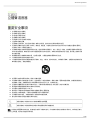
重要安全事項!
必須閱讀這些注意事項。
必須保留這些注意事項。
必須注意所有警告內容。
必須遵循所有注意事項。
不要在靠近水的地方使用本設備。
只能用幹布擦拭設備。
不要堵塞任何通風口。留出足夠的距離,確保充分通風,並安裝在符合製造商要求的位置。
不要將本設備安裝在任何熱源(如明火、散熱器、調溫器、火爐或包括功率放大器在可的其它可能產生熱量的裝置附近。
不要將任何明火火源放置在產品上。
不要破壞帶極性或接地類型插頭的安全功能。極性插頭帶有兩個插片,其中一個比另一個寬。接地類型插頭帶有兩個插片
和第三個接地插腳。較寬的插片或第三個插腳是為安全目的設定的。如果提供的插頭無法插入插座,請向電工諮詢如何更
換合適的插座。
保護電源線防止被腳踩踏或被夾緊,尤其是在插頭、方便插座和機身電源線的引出處。
只能使用製造商指定的連接部件/附件。
只能使用製造商指定的或隨設備售出的手推車、支座、三角架、托架或支撐台。如果使用手推車,在移動裝有設備的手推
車時應注意安全,避免設備翻落。
在雷電天氣或長時間不使用時,應拔下設備的插頭。
所有維修均應由合格的維修人員執行。在設備因以下情況被損壞時,應進行維修:電源線或插頭損壞、液體潑濺到設備上
或異物進入設備,設備暴露在雨水或潮濕環境中而無法正常工作,或摔落到地上。
不要將本設備暴露在可能滴水和濺水的地方。不要將裝有液體的容器(如花瓶等)放在本設備頂部。
電源插頭或電器轉接頭應保持在隨時可用的狀態。
本裝置的空氣噪聲不超過 70dB (A)。
應將符合 I 類標準的設備連接到帶有接地保護裝置的主電源插座。
為降低起火或電擊危險,不要將本設備暴露在雨中或潮濕環境下。
不要嘗試改裝本產品。 這樣做會導致人身傷害和/或產品故障。
應在技術規格指定的溫度範圍內操作此產品。
這個符號表示本設備中存在可能導致觸電的危險電壓。
這個符號表示本設備附帶的說明書中具有重要的操作和維護說明。
警告:本設備中的電壓具有致命危險。設備內部沒有用戶可維修的部件。所有維修均應由合格的維修人員執行。如果改變了廠方
設定的工作電壓,則安全合格證書不再適用。

Shure Incorporated
4/18
•
•
•
•
•
•
•
•
•
•
•
•
•
General Description
The Shure Model SCM262 is a stereo mixer intended for sound reinforcement applications that integrate microphones with
consumer stereo products. It incorporates two active-balanced microphone inputs with three unbalanced stereo aux level
inputs.
The SCM262 Stereo Mixer is designed for restaurants, classrooms, corporate training, aerobics classes, and other situations
where a paging/public announcement system is combined with background music or other program material.
Features
Designed to combine paging with background music
One active-balanced, XLR microphone input channel
One active-balanced XLR microphone and 1/4-in. TRS line input channel
Three STEREO INPUT channels
Stereo AUX level OUTPUTs
Stereo MIC/LINE OUTPUTs
BASS and TREBLE tone controls on the master output
1/2-rack chassis
12 V phantom power for condenser microphones
Internal power supply
Removable power cable
Ducking function (defeatable)
Jukebox mute function (defeatable)
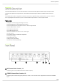
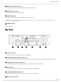
Front Panel
① MIC Channel Gain Controls, 1-2.
Control the gain levels of the MIC channels and LINE IN 2 (MIC 2).
② STEREO Channel Gain Controls, 1-3.
Control the gain levels from CD players, juke boxes, VCRs, or other consumer stereo equipment connected to the STEREO
inputs.

Shure Incorporated
5/18
③ BASS and TREBLE Controls.
Control the boost/cut of the low- and high-frequency of the shelving filters.
④ MASTER Gain Control.
Allows adjustment of the overall output gain.
⑤ POWER Indicator.
Lights up to indicate when the unit is plugged in and receiving power.
The SCM262 does not have a power switch. To turn the unit off, unplug the power cord or use an external power strip with a switch. However, it can remain
plugged in as it uses very little power when idle.
⑥ POWER Switch.
Country dependent.
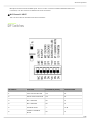
Rear Panel
① Power Connector.
Accepts 100-120 Vac (SCM262) or 220-240 Vac (SCM262E).
② Left/Right MIC/LINE Output Connectors.
These 1/4-in. connectors are stereo, balanced outputs for use with professional audio equipment. Controlled by DIP switch.
③ Left/Right AUX Output Connectors.
These phono jacks are stereo, unbalanced outputs for use with consumer stereo equipment.
④ DIP Switches.
These allow you to adjust the SCM262 for specific applications. See DIP Switches.
⑤ Left/Right STEREO INPUTS, 1-3.
These phono jacks are stereo inputs for connection to consumer stereo devices.
⑥ MIC Channel 2 INPUT.

Shure Incorporated
6/18
Microphone channel 2 has two available inputs. There is a 1/4-in. connector for balanced/unbalanced line-level
connections, or an XLR connector for balanced mic-level connections.
⑦ MIC Channel 1 INPUT.
This is an XLR connector for balanced mic-level connections.
DIP Switches
DIP SWITCH FUNCTION POSITION UP (default) POSITION DOWN
1 LEFT OUTPUT MIC/LINE Line Mic
2 RIGHT OUTPUT MIC/LINE Line Mic
3 MIC 1 DUCKING Off On
4 MIC 2 DUCKING Off On
5 DUCKING LEVEL –∞ -20 dB
6
STEREO 3 JUKEBOX
MUTE
Off On

Shure Incorporated
7/18
1.
2.
3.
4.
5.
6.
1.
2.
3.
DIP SWITCH FUNCTION POSITION UP (default) POSITION DOWN
7 12 V PHANTOM Off On
LEFT/RIGHT OUTPUT MIC/LINE: DIP switches 1 and 2 adjust the left and right outputs for line- or mic-level operation.
MIC 1/MIC 2 Ducking: When ducking is on, the SCM262 will automatically lower the gain of all STEREO inputs when
someone is speaking into one of the microphones.
DUCKING LEVEL: Adjusts the amount of STEREO channel gain reduction when ducking is activated.
STEREO 3 JUKEBOX MUTE: This DIP switch turns the Juke Box Mute feature on or off. When on, any source connected to
STEREO 3 will mute STEREO 1 and 2 inputs.
PHANTOM POWER: When in the down position, this switch activates a 12 V phantom power source for condenser
microphones. Phantom power does not affect the operation of balanced, dynamic microphones, so one can be connected to
the SCM262 in combination with a condenser microphone.
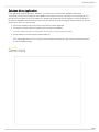
Applications
General Application
This is a general setup for most situations which require the combined use of a professional microphone and consumer stereo
equipment. Using this general setup, there are several other options available for further adjusting the SCM262 for your sound
system. See the diagram on the facing page.
Turn all gain controls counterclockwise.
Connect L/R STEREO INPUTS of the SCM262 to the L/R stereo outputs of the desired stereo audio equipment (CD
players, VCRs, televisions, juke boxes, etc.).
Connect microphone(s) to the MIC INPUTS on the SCM262.
For microphones which require phantom power, such as condenser microphones, place DIP switch 7 in the down
position (phantom power on).
Connect the L/R outputs of the SCM262 to the L/R inputs of the amplifier.
Note: If you are using a consumer stereo amplifier, use the AUX OUTs. If you are using a professional audio power amplifier, use the LINE OUTs.
The MIC/LINE and AUX OUTPUTs can be used simultaneously to feed two separate amplifiers.
Apply power to the mixer by connecting the supplied power cable between the power connector on the mixer and the
appropriate AC power supply. The green POWER LED will illuminate to indicate that the mixer is powered on.
Note: The SCM262 has no power switch*. It is designed to be plugged into a power strip which supports the whole sound system. A typical power
strip will have a power switch, so that when the power strip is powered on, the SCM262 is powered on. (*Power Switch, country dependent).
Paging with Ducking Application
With Ducking on, the SCM262 will automatically sense when someone is talking into one of the microphones and lower the
volume of the music so the talker can be heard more clearly. Once the talker is finished, the music resumes.
Use a microphone with an ON/OFF or pushbutton switch for the Paging with Ducking Application. A microphone without a switch will false-trigger, causing
unwanted interruptions in the program material.
Connect the SCM262 to the sound system as described in General Application.
Set DIP switch 3 or 4 to the down position to activate ducking for microphone channel 1 or 2, respectively.
Set DIP switch 5 position. The Down position sets the ducking so that the program sound is lowered 20 dB when
someone uses a microphone. The Up position sets the ducking so that the program sound is muted when someone
uses a microphone.

Shure Incorporated
8/18
1.
2.
3.
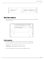
Jukebox Mute Application
In this application, designed primarily for Jukeboxes, any sound source connected to the STEREO 3 channels will
automatically mute any sound coming over the STEREO 1 and 2 channels. This way, a CD player can be playing music, and
then when someone plays a song on the Jukebox, the SCM262 will automatically mute the CD player channels and switch to
the Jukebox. STEREO 1 and 2 channels will remain muted for about 30 seconds after program material is finished, to allow the
jukebox time to move on to the next song.
Connect the SCM262 to the sound system as described in General Application.
Connect the L/R audio outputs of the jukebox to the L/R inputs of STEREO 3.
This feature is designed especially for use with jukeboxes, but will work for any equipment connected to STEREO 3.
Set DIP Switch 6 to the down position (Jukebox Mute on).
If the ducking application is used in conjuction with the Jukebox Mute application, then activated microphones will mute
or duck the STEREO 3 input.
Connections

Shure Incorporated
9/18
1.
2.
3.
4.
5.
內部修改
Internal Modifications
Voltages in this equipment are hazardous to life. No user-serviceable parts inside. Refer all servicing and modifications to
qualified service personnel.
Disassembly
To access the printed circuit board (pc board) for internal modifications, use the following steps:
Unplug the power cord.
Remove the knobs and retainer nuts from the front panel.
Remove the two screws at each bottom corner of the front panel.
Remove the four screws at each corner of the back panel.
Slide the back panel and pc board out from the rear of the chassis.
When reassembling the SCM262, DO NOT OVERTIGHTEN the knob retainer nuts. Use a minimal amount of force to
secure the nut (0.6-0.8 N-m (5-7 in-lb)). Damage to the internal components will result if too much force is used.
Mono Mixer Modification
This modification allows all the inputs to be mixed to a single mono signal sent over both the left and right outputs.
Short jumper X203.
Phantom Power Disable
This modification disables the phantom power per channel.
To disable the phantom power from mic 1, remove resistor R121. To disable the phantom power from mic 2, remove resistor
R122.
15 dB Mic Preamplifier Pad
When a microphone has an extremely high signal, getting the desired gain might be difficult - a small turn of the gain control
might change the sound from a whisper to deafeningly loud. This modification adds a 15 dB Mic preamplifier pad to allow more
accurate gain adjustment with extremely high microphone signals.
Remove R160 (mic 1) or R183 (mic 2).
Hard Panning MIC Channels
To remove MIC 1 from the left outputs, remove R912. To remove MIC 1 from the right outputs, remove R913.

Shure Incorporated
10/18
To remove MIC 2/LINE 2 from the left outputs, remove R910. To remove MIC 2/LINE 2 from the right outputs, remove R911.
Low-Cut Filter
To eliminate the 80 Hz, low-cut filter, remove resistor R501 (mic 1), or resistor R519 (mic 2). Place a 10 to 33 µF capacitor in
X501 (mic 1) or R502 (mic 2). The polarity of the capacitor does not matter. To change the frequency of the low cut filter,
remove resistor R501 (mic 1) or R519 (mic2), and place the proper capacitor into X501 (mic 1) or X502 (mic 2) to get the
desired corner frequency.
The following tables list the low-cut frequency corners for some of the most common capacitor values:
Capacitor Value Corner Frequency
.033 µF 803 Hz
.047 µF 564 Hz
.068 µF 390 Hz
.1 µF 265 Hz
.22 µF 120 Hz
Capacitor Value Corner Frequency
.33 µF 80 Hz
.47 µF 56 Hz
.68 µF 39 Hz
1.0 µF 26.5 Hz
2.2 µF 12 Hz
Ducking Depth
This modification adjusts the level of ducking depth attenuation of the input channels when ducking is activated.
The aux ducking depth may be changed by removing resistor R213 and inserting a resistor into jumper X202. Use the following
tables to determine the proper resistor value for the desired ducking depth.
Ducking Depth Resistor Value
6 dB 4,000 Ω
9 dB 5,000 Ω
15 dB 7,500 Ω
20 dB 10,000 Ω
24 dB 12,000 Ω
29 dB 15,000 Ω
Ducking Depth Resistor Value
36 dB 20,000 Ω

Shure Incorporated
11/18
•
•
•
•
•
•
•
•
Ducking Depth Resistor Value
42 dB 25,000 Ω
47 dB 30,000 Ω
50 dB 33,000 Ω
55 dB 40,000 Ω
Ducking Threshold
This modification adjusts the threshold for activating the ducking circuit.
The ducking threshold can be raised or lowered by first removing resistor R333, and then placing a resistor (R) at jumper X303.
To lower the ducking threshold, use a resistor value (R) less than 2k ohms. To raise the ducking threshold, use a resistor value
(R) greater then 2k ohms.
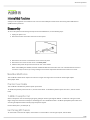
Supplied Hardware
4 rubber feet. For stand-alone installation.
1 rackmount bracket, long. For half-rack (single unit) installations.
1 rackmount bracket, short. For half-rack (single) or dual-mount installations.
2 straddle brackets. For dual-mount or fixed installations.
12 bracket screws, 1/4-in. (6 mm). For securing the brackets to the chassis.
4 rackmount screws, 1 in. (2.5 cm). For mounting the unit in a rack.
4 plastic washers. For use with the supplied rackmount screws.
4 wood screws, 1/2 in. (1.25 cm). For fixed installations.

Shure Incorporated
12/18
1.
1.
2.
3.
Rackmount Installation
The SCM262 can be mounted as a single unit or dual-mounted with either another SCM262 or another Shure half-rack unit
such as the SCM268 or DFR11EQ. Attach the rackmount brackets using one of the following methods:
Single unit (half-rack) installation:
Attach the short and long rackmount brackets to the SCM262 with eight (8) of the supplied bracket screws.
Dual-mounted installation:
Connect the two units together side-by-side using two (2) straddle brackets. The brackets should straddle the recessed
edges on the top and bottom of each chassis. Fasten them using eight (8) bracket screws.
Be sure to use both straddle brackets-one on the top and one on the bottom.
Attach the short rackmount brackets to the outsides of the combined units with eight (8) of the bracket screws.
After attaching the brackets, mount the unit in an equipment rack using the supplied rackmount screws and plastic
washers.

Shure Incorporated
13/18
1.
1.
2.
Stand-Alone Installation
Adhere the four (4) supplied rubber feet to the bottom of the unit at each corner. This will keep it from sliding and
protect the table surface.
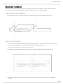
Fixed Installation
To permanently affix the SCM262 above or below a table, shelf, or counter top, use the following steps:
Fasten the straddle brackets to the recessed edges of the chassis using four (4) bracket screws.
Top Mount: Fasten the straddle brackets to the bottom of the unit.
Hanging Mount: Fasten the straddle brackets to the top of the unit.
Fasten the straddle brackets to the surface using the four (4) supplied wood screws.

Shure Incorporated
14/18

Shure Incorporated
15/18
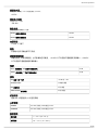
規格
頻率響應
1
千赫下
話筒/線路開關 150 赫茲 到 20 千赫 ±2 dB
輔助輸入 20 赫茲 到 20 千赫 ±2 dB
低切濾波器
-6 dB/倍頻程低於 80 赫茲

Shure Incorporated
16/18
總諧波失真
1
千赫茲
, +4 dBu
輸出
, +0 dB
下的混音器輸出(
MASTER
)
<0.25%
等效輸入噪聲
均衡音源
150Ω, A-
加權
-128 dBV
輸出噪聲
頻道控制器逆時針旋轉到底
, A-
加權
Master 逆時針旋轉到底 -95 dBV
Master 順時針旋轉到底 -59 dBV
共模抑制
>70 dB, 1 千赫下
極性
所有輸入到所有輸出都不可反相。
超載和短路保護
將輸出短接,即使時間較長,也不會導致任何損害。 +10 dBV 以下的信號不會損害麥克風輸入;+28 dBV
以下的信號不會損害線路和輔助輸入
均衡
Bass(低頻柵形,250 赫茲下的轉角頻率) ±6 dB
Treble(高頻柵形,4 千赫下的轉角頻率) ±6 dB
突降
Mic 通道 1 和 2 電平 -20 dB 或 -∞ dB
Activation time 10 毫秒, 典型
Mic 停用時間 2 秒, 典型
Jukebox Mute 停用時間 30 秒, 典型
幻像電源
通過 680 Ω 電阻器的 12 伏直流開路
工作電壓
SCM262 100–200 伏交流, 50/60 赫茲, 60 mA
SCM262E 220–240 伏交流, 50/60 赫茲, 30 mA
溫度範圍
操作溫度 -7° – 35° C (20° –95° F)
存儲溫度 -29° – 74° C (-20° –165° F)

Shure Incorporated
17/18
外觀尺寸
43 x 218 x 162 毫米 (1.72 x 8.60 x 6.37 英寸)
淨重
1.1 公斤 (2 磅, 5 安士)
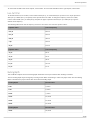
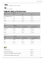
Voltage Gain (typical, controls full clockwise)
Input
Output
Mic Line Aux
Low-impedance mic (150
Ω)
32 dB 72 dB 60 dB
Line -9 dB 31 dB 19 dB
Stereo -5 dB 35 dB 23 dB
Inputs
Input
Impedance
Designed for use with Actual (typical) Input Clipping Level
Mic (XLR) <600 Ω 1.4 kΩ -16 dBV
Line <10 kΩ 155 kΩ +24 dBV
Stereo <2 kΩ 21 kΩ >28 dBV
Outputs
Output
Impedance
Designed for use with Actual (typical) Output Clipping Level
Mic >600 Ω 3 Ω -22 dBV
Line >5 kΩ 300 Ω +18 dBV
Aux ≥10 kΩ 1.5 kΩ +5 dBV
備件
Knob, Master (blue) 95B8752
Knob, Channel Gain (white) 95A8752
Line (Power) Cords: SCM262: 100-120 Vac (US/Canada) 95B8762
Line (Power) Cords: SCM262E: 220-240 Vac (EU) 95B8778

Shure Incorporated
18/18
Fuse: SCM262 (5x20 mm, 250V, 100mA, time delay) 80Z730
SCM262E (5x20 mm, 250v, 40mA, time delay) 80M258
Hardware Kit 90AW8100
連接桿(托架) 53B8443
Single Mount Bracket 53A8484
Dual Mount Bracket 53E8484
選配附件
Line (Power) Cord, 230-240 Vac (UK) 95A8713
服務聲明
如需其他服務或零件資訊,請致電
1-800-516-2525
聯絡
Shure
服務部門。若在美國境外,請聯絡授權的
Shure
服務中心。
認證
本產品符合所有相關歐盟法規的基本要求,並且允許使用 CE 標誌。
可從以下地址獲得“CE 符合性聲明”:www.shure.com/europe/compliance
歐盟授權代表:
Shure Europe GmbH
歐洲、中東、非洲總部
部門:歐洲、中東、非洲批准部
Jakob-Dieffenbacher-Str.12
75031 Eppingen, Germany
電話:+49-7262-92 49 0
傳真:+49-7262-92 49 11 4
電子郵件:[email protected]
-
 1
1
-
 2
2
-
 3
3
-
 4
4
-
 5
5
-
 6
6
-
 7
7
-
 8
8
-
 9
9
-
 10
10
-
 11
11
-
 12
12
-
 13
13
-
 14
14
-
 15
15
-
 16
16
-
 17
17
-
 18
18


Shure SCM262 は、マイクロホンと一般家庭用のステレオ製品を統合する音響補強用途向けのステレオミキサーです。3つのアンバランス・ステレオ補助レベル入力付きの2つのアクティブバランス・マイクロホン入力を備えています。
レストラン、教室、企業研修、エアロビクスクラスなど、ページング/場内放送システムがバックグラウンドミュージックやその他のプログラム素材と組み合わされる状況向けに設計されています。
主な機能は次のとおりです。
- ページングを背景音楽と組み合わせる設計
- アクティブバランスのXLRマイク入力チャンネル1つ
- アクティブバランスのXLRマイクと1/4インチTRSライン入力チャンネル1つ
- ステレオ入力チャンネル3つ
- ステレオAUXレベル出力
- ステレオMIC/ライン出力
- マスター出力の低音と高音のトーンコントロール
- 1/2ラックシャーシ
他の言語で
- English: Shure SCM262 User guide