ˎ
ˎ
ˎ
VCT-55LH
XLR
WEB
ˎ
ˎ
ˎ
ˎ
ˎ
ˎ
ˎ
1 2 3
4 REC CH SELECT
INPUT1 5 ATT INPUT1
6 INPUT1
LINE/MIC/MIC+48V
7 ATT
INPUT2
8 INPUT2
LINE/MIC/MIC+48V
9 LOW CUT
INPUT1 10 AUTO/MAN CH1
11 AUDIO LEVEL
CH1
12 AUTO/MAN
CH2
13 AUDIO LEVEL
CH2
14 LOW CUT
INPUT2 15
/ Operating Instructions /
Mode d’emploi / Manual de
instrucciones /
XLR-K2M
XLR
XLR Adaptor Kit
Kit adaptateur XLR
© 2014 Sony Corporation Printed in Japan
4-546-775-
01
(1)
4
10 11 12 13 14
1
17
18
19
20 21
15
16
3
2
5 6 7 8 9
1
3
2
2
1
4
5
3
2
5
1
3
22
(Suite à la page arrière)
16 17
18
19 20 INPUT2
21 INPUT1
20 21
6 8
5 7
4
10 11 12 13
/ 9 14
XLR
1
XLR
2 XLR
3 XLR
ˎ
XLR
XLR
XLR
1
-1
2
3 ECM-XM1
4 XLR INPUT1
1 INPUT1
5 XLR
-19
ˎ
ˎ
-18
1 INPUT 1 LINE/MIC/MIC+48V
MIC+48V
2 REC CH SELECT INPUT1 CH1
CH2
CH1 CH2
CH1 CH1
INPUT1 /INPUT2
MIC
1 CH1 CH2 AUTO/
MAN
MAN
2 AUDIO LEVEL
AUTO/MAN AUTO
INPUT1 /INPUT2
LOW CUT INPUT1 LOW CUT
INPUT2 ON
1
INPUT1 /INPUT2
INPUT1/INPUT2
LINE/MIC/MIC+48V
LINE
MIC
+48V
MIC+48V
ˎ
MIC+48V +48V
ˎ
INPUT1/
INPUT2
LINE/MIC/MIC+48V LINE
2
INPUT1/INPUT2 LINE/MIC/MIC+48V MIC
MIC+48V ATT INPUT1/INPUT2
ECM-XM1 ATT 10dB
ATT 0dB -60dBu
ATT 10dB
-50dBu
ATT 20dB
-40dBu
ˎ
INPUT1/INPUT2 LINE/MIC/MIC+48V LINE
+4dBu ATT
3
REC CH SELECT INPUT1
REC CH SELECT
INPUT1 CH1 CH2
CH1 CH2
INPUT1
CH1
CH2
CH1
INPUT1
CH1
INPUT2
CH2
ˎ
XLR 3PIN 2
INPUT1 Lch INPUT2 Rch REC
CH SELECT
INPUT1 CH1
XLR XLR-A2M
116.5 mm 105.5 mm 75 mm
ECM-XM1
21 mm 162 mm
XLR XLR-A2M 250 g
ECM-XM1 121.5 g
0 40
-20 +60
INPUT1/INPUT2 XLR 3
MIC -60/-50/-40 dBu 3 k
LINE +4 dBu 10 k
0 dBu=0.775 Vrms
XLR XLR-A2M 1 ECM-XM1 1
1 1
1
ˎ
ˎ
ˎ
1
7
ˎ
XLR-K2M
ˎ
ˎ
Before operating the product, please read this manual
thoroughly and retain it for future reference.
WARNING
To reduce fire or shock hazard, do not expose the unit to
rain or moisture.
Keep out of reach of small children to prevent accidental
swallowing.
For the Customers in the U.S.A.
CAUTION
You are cautioned that any changes or modifications not
expressly approved in this manual could void your authority
to operate this equipment.
Note:
This equipment has been tested and found to comply
with the limits for a Class B digital device, pursuant to Part
15 of the FCC Rules. These limits are designed to provide
reasonable protection against harmful interference in a
residential installation. This equipment generates, uses,
and can radiate radio frequency energy and, if not installed
and used in accordance with the instructions, may cause
harmful interference to radio communications. However,
there is no guarantee that interference will not occur in a
particular installation. If this equipment does cause harmful
interference to radio or television reception, which can be
determined by turning the equipment o and on, the user
is encouraged to try to correct the interference by one or
more of the following measures:
—Reorient or relocate the receiving antenna.
—Increase the separation between the equipment and
receiver.
—Connect the equipment into an outlet on a circuit dierent
from that to which the receiver is connected.
—Consult the dealer or an experienced radio/TV technician
for help.
THIS DEVICE COMPLIES WITH PART 15 OF THE FCC
RULES. OPERATION IS SUBJECT TO THE FOLLOWING TWO
CONDITIONS:
(1) THIS DEVICE MAY NOT CAUSE HARMFUL INTERFERENCE,
AND (2) THIS DEVICE MUST ACCEPT ANY INTERFERENCE
RECEIVED, INCLUDING INTERFERENCE THAT MAY CAUSE
UNDESIRED OPERATION.
For the Customers in Europe
Disposal of Old Electrical & Electronic
Equipment (Applicable in the European
Union and other European countries with
separate collection systems)
This symbol on the product or on its
packaging indicates that this product
shall not be treated as household waste.
Instead it shall be handed over to the
applicable collection point for the recycling of electrical
and electronic equipment. By ensuring this product is
disposed of correctly, you will help prevent potential
negative consequences for the environment and human
health, which could otherwise be caused by inappropriate
waste handling of this product. The recycling of materials
will help to conserve natural resources. For more detailed
information about recycling of this product, please contact
your local Civic Oce, your household waste disposal
service or the shop where you purchased the product.
< Notice for the customers in the
countries applying EU Directives >
Manufacturer: Sony Corporation, 1-7-1 Konan Minato-ku
Tokyo, 108-0075 Japan
For EU product compliance: Sony Deutschland GmbH,
Hedelfinger Strasse 61, 70327 Stuttgart, Germany
Features
The XLR-K2M is a kit including an XLR Adaptor for a device
equipped with a Multi Interface Shoe and a microphone.
Some camera models with a Multi Interface Shoe cannot be
used with this kit.
For details on compatible camera models of this unit, visit
the website of Sony in your area, or consult your dealer of
Sony or local authorized Sony service facility.
Notes on use
• The microphone is a precision instrument. Do not drop,
knock it, or subject it to excessive shock.
• If the microphone is placed near speakers, a howling
eect (acoustic feedback) may occur. If this happens,
place the microphone as far as possible from the
speakers, or lower the volume of the speaker.
• Do not hold this unit to pick up or carry the camera when
attached.
• To carry this unit, remove it from the camera, attach
the connector protect cap to this unit and put it in the
supplied carrying case.
Notes on changing the lens
• Before changing the lens, remove this unit from the
camera.
• Before changing the lens, check whether there are any
fibers from the wind screen on the lens or camera body.
Brush any fibers o with a blower etc. and then change
the lens.
• After using this unit, cleaning the lens is recommended.
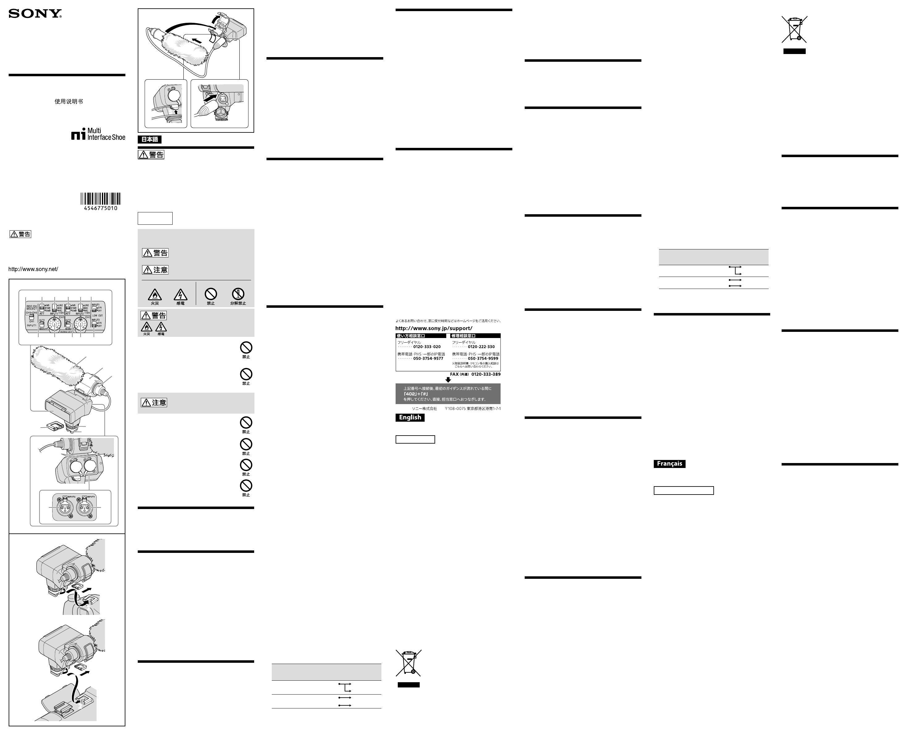
Identifying the parts
1 Wind screen 2 Microphone 3 Microphone holder
4 REC CH SELECT (INPUT1) switch 5 ATT (INPUT1) switch
6 INPUT1 (LINE/MIC/MIC+48V) switch 7 ATT (INPUT2) switch
8 INPUT2 (LINE/MIC/MIC+48V) switch
9 LOW CUT (INPUT1) switch 10 AUTO/MAN (CH1) switch
11 AUDIO LEVEL (CH1) dial 12 AUTO/MAN (CH2) switch
13 AUDIO LEVEL (CH2) dial 14 LOW CUT (INPUT2) switch
15 Lock dial 16 Multi Interface foot
17 Connector protect cap 18 Release lever 19 Cable holder
20 INPUT2 jack 21 INPUT1 jack
Inputting external sound: 20, 21
Selecting a sound source: 6, 8
Selecting a sound source level: 5, 7
Selecting channel setting for recording: 4
Selecting the recording level: 10, 11, 12, 13
Switching wind noise reduction to ON/OFF: 9, 14
Attaching the XLR Adaptor
1 Detach the connector protect cap from
the connector plug of the XLR Adaptor.
Check that the lock pin is not protruding from the bottom
of the Multi Interface foot of the XLR Adaptor.
2 Attach the Multi Interface foot of the XLR
Adaptor to the Multi Interface Shoe of
the camera.
3 Tighten the lock dial of the XLR Adaptor
securely.
Notes
• Insert the Multi Interface foot of the XLR Adaptor fully into
the Multi Interface Shoe of the camera, and tighten the
lock dial securely. Make sure this unit is attached securely.
When detaching the XLR Adaptor
Fully loosen the lock dial of the XLR Adaptor before
detaching the XLR Adaptor.
Attaching the microphone
1 Attach the wind screen (-1) to the
microphone.
2 Unlock the stopper of the microphone
holder and open the cover.
3 Place the microphone into the holder so
that the model name (ECM-XM1) on the
microphone faces upward. Then close the
cover and firmly lock the stopper.
4 Connect the connector plug of the
microphone to the INPUT1 jack on the
XLR Adaptor.
Connect the connector plug of the microphone to the
INPUT1 jack if you connect one device.
5 Put the microphone cable into the cable
holder (-19) on the XLR Adaptor.
• See “Audio setup” for audio recording.
• If the cable is pulled with too much force or attached to
the cable holder too loosely, the microphone attached
to the microphone holder may tilt a lot.
To get the full anti-vibration eect, make sure the
microphone is not tilting too much.
When detaching the microphone cable
Detach the microphone from the microphone holder.
Unplug the microphone plug while pressing the release
lever (-18) down.
Audio setup
Using the supplied microphone
You can record unidirectional monaural sound with the
microphone.
1 Set the INPUT1 (LINE/MIC/MIC+48V)
switch to MIC+48V.
2 Set the REC CH SELECT (INPUT1) switch to
CH1·CH2.
This setting enables recording on both CH1 and CH2. Set
the switch to CH1 if you want to record on CH1 only.
Adjusting the recording level
You can adjust the recording level input from the INPUT1/
INPUT2 jacks.
You cannot adjust the recording level of the internal
microphone and MIC input jack.
1 Set the AUTO/MAN (CH1/CH2) switch of
the channel to be adjusted to MAN.
2 Turn the AUDIO LEVEL dial to adjust the
volume to the proper level.
Check that the volume is at the proper level, with
headphones or audio level meter.
To restore automatic adjustment
Set the AUTO/MAN (CH1/CH2) switch to AUTO.
Reducing wind noise
You can reduce wind noise input from the INPUT1/INPUT2
jacks.
Set the LOW CUT (INPUT1) switch or LOW
CUT (INPUT2) switch to ON.
Using an external audio device
Set as follows when you use a microphone other than the
supplied microphone or an external audio device (mixer,
etc.).
1 Select the sound source to be input.
Set the INPUT1/INPUT2 (LINE/MIC/MIC+48V) switch
according to the device to be connected to the INPUT1/
INPUT2 jacks.
External audio device (mixer, etc.): LINE
Dynamic microphone or microphone with built-in
battery: MIC
Microphone that is 48V phantom power compliant:
MIC+48V
Notes
• If you connect a device that does not support 48V
phantom power, malfunction may result from setting
this switch to MIC+48V. Check before connecting the
device.
• If noise from the unused jack bothers you, set the
INPUT1/INPUT2 (LINE/MIC/MIC+48V) switch of the
unused jack to LINE.
2 Set the input level of the microphone.
When the INPUT1/INPUT2 (LINE/MIC/MIC+48V) switch is
set to MIC or MIC+48V, you can set the input level with
the ATT (INPUT1/INPUT2) switch.
Adjust according to the microphone sensitivity.
ATT 10dB is recommended when you use the supplied
microphone (ECM-XM1).
The input levels are as follows.
ATT 0dB: -60dBu
ATT 10dB: -50dBu
ATT 20dB: -40dBu
Notes
• When the INPUT1/INPUT2 (LINE/MIC/MIC+48V) switch
is set to LINE, the input level is fixed to +4dBu. Even
if you reset the ATT switch, the input level does not
change.
3 Set the channel to be recorded.
You can select the channel to be recorded, with the REC
CH SELECT (INPUT1) switch.
Position of the REC
CH SELECT (INPUT1)
switch
Audio recorded on CH1 & CH2
CH1·CH2
INPUT1
CH1
CH2
CH1
INPUT1
CH1
INPUT2
CH2
• To use a stereo microphone with two XLR (3PIN) plugs,
connect Lch to the INPUT1 jack and Rch to the INPUT2
jack, and set the REC CH SELECT (INPUT1) switch to
CH1.
Specifications
Maximum dimensions (Approx.)
XLR Adaptor (XLR-A2M) unit
116.5 mm × 105.5 mm × 75 mm (w/h/d)
(4 5/8 in. × 4 1/4 in. × 3 in.)
(excluding the cord and projecting parts)
Microphone (ECM-XM1)
21 mm × 162 mm (Diameter/Length)
(27/32 in. × 61/2in.)
(excluding the wind screen and cord)
Mass (Approx.)
XLR Adaptor (XLR-A2M) unit 250 g (8 oz)
Microphone (ECM-XM1) 121.5 g (4 oz)
Operating temperature 0 °C to 40 °C (32 °F to 104 °F)
Storage temperature -20 °C to +60 °C (-4 °F to +140 °F)
Input jacks
INPUT1/INPUT2 jacks: XLR3-pin, female
MIC: -60 dBu /-50 dBu /-40 dBu, 3 kΩ(kilohms)
LINE: +4 dBu, 10 kΩ (kilohms)
(0 dBu=0.775 Vrms)
Included items
XLR Adaptor (XLR-A2M) (1), Microphone (ECM-XM1) (1),
Wind screen (1), Connector protect cap(1), Carrying case
(1), Set of printed documentation
Design and specifications are subject to change without
notice.
Multi Interface Shoe is a trademark of Sony Corporation.
Avant d’utiliser ce produit, prière de lire attentivement ce
mode d’emploi et de le conserver pour toute référence
future.
AVERTISSEMENT
Afin de réduire les risques d’incendie ou de décharge
électrique, n’exposez pas cet appareil à la pluie ou à
l’humidité.
Rangez hors de portée des enfants pour éviter toute
ingestion accidentelle.
À l’intention des clients aux É.-U.
AVERTISSEMENT
Par la présente, vous êtes avisé du fait que tout
changement ou toute modification ne faisant pas l’objet
d’une autorisation expresse dans le présent manuel
pourrait annuler votre droit d’utiliser l’appareil.
Note
L’appareil a été testé et est conforme aux exigences d’un
appareil numérique de Classe B, conformément à la Partie
15 de la réglementation de la FCC.
Ces critères sont conçus pour fournir une protection
raisonnable contre les interférences nuisibles dans un
environnement résidentiel. L’appareil génère, utilise et peut
émettre des fréquences radio; s’il n’est pas installé et utilisé
conformément aux instructions, il pourrait provoquer des
interférences nuisibles aux communications radio.
Cependant, il n’est pas possible de garantir que des
interférences ne seront pas provoquées dans certaines
conditions particulières. Si l’appareil devait provoquer des
interférences nuisibles à la réception radio ou à la télévision,
ce qui peut être démontré en allumant et éteignant
l’appareil, il est recommandé à l’utilisateur d’essayer de
corriger cette situation par l’une ou l’autre des mesures
suivantes :
—Réorienter ou déplacer l’antenne réceptrice.
—Augmenter la distance entre l’appareil et le récepteur.
—Brancher l’appareil dans une prise ou sur un circuit
diérent de celui sur lequel le récepteur est branché.
—Consulter le détaillant ou un technicien expérimenté en
radio/téléviseurs.
Cet appareil est conforme à la section 15 des règlements
FCC. Son fonctionnement est soumis aux deux conditions
suivantes : (1) cet appareil ne doit pas provoquer
d’interférences nuisibles, (2) cet appareil doit accepter toute
interférence, y compris celles susceptibles de provoquer son
fonctionnement indésirable.
Pour les clients en Europe
Traitement des appareils électriques et
électroniques en fin de vie (Applicable
dans les pays de l’Union Européenne et
aux autres pays européens disposant de
systèmes de collecte sélective)
Ce symbole, apposé sur le produit ou sur son
emballage, indique que ce produit ne doit
pas être traité avec les déchets ménagers.
Il doit être remis à un point de collecte
approprié pour le recyclage des équipements électriques et
électroniques. En vous assurant que ce produit sont mis au
rebut de façon appropriée, vous participez activement à la
prévention des conséquences négatives que leur mauvais
traitement pourrait provoquer sur l’environnement et sur la
santé humaine. Le recyclage des matériaux contribue par
ailleurs à la préservation des ressources naturelles. Pour
toute information complémentaire au sujet du recyclage de
ce produit, vous pouvez contacter votre municipalité, votre
déchetterie locale ou le point de vente où vous avez acheté
le produit.
< Avis aux consommateurs des pays
appliquant les Directives UE >
Fabricant: Sony Corporation, 1-7-1 Konan Minato-ku Tokyo,
108-0075 Japon
Pour toute question relative à la conformité des produits
dans l’UE: Sony Deutschland GmbH, Hedelfinger Strasse 61,
70327 Stuttgart, Allemagne
Caractéristiques
Le XLR-K2M est un kit comprenant un adaptateur XLR pour
appareil à grie multi-interface et un microphone.
Certains modèles d’appareils photo/caméscopes à grie
multi-interface ne peuvent pas être utilisés avec ce kit.
Pour plus de détails sur les modèles d’appareils photo/
caméscopes compatibles avec cet accessoire, consultez le
site Web de Sony de votre région, ou adressez-vous à votre
revendeur Sony ou au service après-vente agréé Sony local.
Remarques sur l’emploi
• Le microphone est un instrument de précision. Ne le
laissez pas tomber, ne le cognez pas et ne le soumettez
pas à des chocs.
• Si le microphone est placé près d’enceintes, un hurlement
(rétroaction acoustique) peut se produire. Dans ce cas,
éloignez le plus possible le microphone des enceintes, ou
bien réduisez le volume du microphone.
• Ne soulevez pas ou ne tenez pas l’appareil photo/
caméscope par cet accessoire lorsque ce dernier est
rattaché.
• Pour transporter cet accessoire, retirez-le de l’appareil
photo/caméscope, rattachez le capuchon de protection
de connecteur et rangez-le dans l’étui de transport fourni.
Remarques sur le changement d’objectif
• Avant de changer d’objectif, retirez cet accessoire de
l’appareil photo/caméscope.
• Avant de changer d’objectif, assurez-vous de l’absence de
fibres de la bonnette antivent sur l’objectif ou l’appareil
photo/caméscope. Retirez toute fibre avec un souet, etc.
avant de changer d’objectif.
• Il est conseillé de nettoyer l’objectif après l’utilisation de
cet accessoire.
Identification des éléments
1 Bonnette antivent 2 Microphone
3 Support de microphone
4 Commutateur REC CH SELECT (INPUT1)
5 Commutateur ATT (INPUT1)
6 Commutateur INPUT1 (LINE/MIC/MIC+48V)
7 Commutateur ATT (INPUT2)
8 Commutateur INPUT2 (LINE/MIC/MIC+48V)
9 Commutateur LOW CUT (INPUT1)
10 Commutateur AUTO/MAN (CH1)
11 Molette AUDIO LEVEL (CH1)
12 Commutateur AUTO/MAN (CH2)
13 Molette AUDIO LEVEL (CH2)
14 Commutateur LOW CUT (INPUT2)
15 Molette de verrouillage 16 Sabot multi-interface
17 Capuchon de protection de connecteur
18 Levier de libération 19 Support de câble
20 Prise d’entrée INPUT2 21 Prise d’entrée INPUT1
Transmission d’un son externe: 20, 21
Sélection d’une source sonore: 6, 8
Sélection du niveau d’une source sonore: 5, 7
Sélection d’un canal pour l’enregistrement: 4
Sélection du niveau d’enregistrement: 10, 11, 12, 13
Activation/désactivation de la réduction du bruit du
vent: 9, 14
Fixation de l’adaptateur
XLR
1 Détachez le capuchon de protection de
connecteur de la fiche-connecteur de
l’adaptateur XLR.
Assurez-vous que la goupille de verrouillage ne dépasse
pas de la partie inférieure du sabot multi-interface de
l'adaptateur XLR.
2 Raccordez le sabot multi-interface
de l’adaptateur XLR à la grie multi-
interface de l’appareil photo/caméscope.
3 Serrez correctement la molette de
verrouillage de l’adaptateur XLR.
Remarques
• Insérez à fond le sabot multi-interface de l’adaptateur
XLR dans la grie multi-interface de l’appareil photo/
caméscope, puis serrez la molette de verrouillage.
Assurez-vous que cet accessoire est bien rattaché.
Pour détacher l’adaptateur XLR
Desserrez complètement la molette de verrouillage de
l’adaptateur XLR avant de détacher l’adaptateur XLR.

